BrassEm
-
Posts
268 -
Joined
-
Last visited
Content Type
Profiles
Forums
Events
Everything posted by BrassEm
-
That is excellent news! Learning the software is hard won, but worth it. It would be great to see an update when you get time.
-
Beautiful pics but they really hurt my eyes. What stands out like two big red dogs balls? What is the ratio of the upper roundel for the british colour scheme for this model spit? Just saying...
-
Absolutely interested Frusheen! That functionality will most definitely be needed. I hope that you would be kind enough to post your script when you can. I hope you get the recompile over at XSimulator soon. They seem to have a comprehensive set of plug-ins.
-
G'day Frusheen, The PM system doesn't allow more than 5,000 characters so I am posting here. This is my export.lau that works with X-Sim. If there are problems let us know. Cheers, Brass. (Some of the comments are for my force feedback devices.) gHost = "127.0.0.1" gPort = 9089 gExportInterval = 0.067 gExportLowTickInterval = 1 gEveryFrameArguments = {[540]="%0.1f", [541]="%0.1f", [542]="%0.1f", [730]="%0.1f", [731]="%0.1f", [732]="%0.1f", [76]="%.4f", [77]="%.4f", [78]="%.4f", [80]="%.4f", [84]="%.4f", [85]="%.4f", [70]="%.4f", [73]="%.4f", [82]="%.4f", [83]="%.4f", [13]="%.4f", [14]="%.4f", [48]="%.4f", [12]="%.4f", [4]="%.4f", [55]="%0.1f", [17]="%.4f", [18]="%.4f", [24]="%.4f", [23]="%.4f", [25]="%0.1f", [19]="%0.1f", [26]="%0.1f", [20]="%.4f", [21]="%.4f", [27]="%.4f", [63]="%.4f", [64]="%.4f", [65]="%0.1f", [715]="%.4f", [40]="%0.1f", [32]="%0.1f", [46]="%0.1f", [34]="%.4f", [36]="%.4f", [47]="%.4f", [41]="%.4f", [33]="%.4f", [35]="%.4f", [662]="%0.1f", [663]="%0.1f", [665]="%0.1f", [664]="%0.1f", [215]="%0.1f", [216]="%0.1f", [217]="%0.1f", [404]="%0.1f", [372]="%0.1f", [373]="%0.1f", [374]="%0.1f", [654]="%1d", [659]="%0.1f", [660]="%0.1f", [661]="%0.1f", [737]="%0.1f", [653]="%.4f", [88]="%.4f", [89]="%.4f", [647]="%.4f", [648]="%.4f", [606]="%0.1f", [608]="%0.1f", [610]="%0.1f", [612]="%0.1f", [614]="%0.1f", [616]="%0.1f", [618]="%0.1f", [619]="%0.1f", [620]="%0.1f", [274]="%.4f", [604]="%.4f", [600]="%0.1f", [281]="%.4f", [289]="%1d", [480]="%0.1f", [481]="%0.1f", [482]="%0.1f", [483]="%0.1f", [484]="%0.1f", [485]="%0.1f", [486]="%0.1f", [487]="%0.1f", [488]="%0.1f", [489]="%0.1f", [490]="%0.1f", [491]="%0.1f", [492]="%0.1f", [493]="%0.1f", [494]="%0.1f", [495]="%0.1f", [496]="%0.1f", [497]="%0.1f", [498]="%0.1f", [499]="%0.1f", [500]="%0.1f", [501]="%0.1f", [502]="%0.1f", [503]="%0.1f", [504]="%0.1f", [505]="%0.1f", [506]="%0.1f", [507]="%0.1f", [508]="%0.1f", [509]="%0.1f", [510]="%0.1f", [511]="%0.1f", [512]="%0.1f", [513]="%0.1f", [514]="%0.1f", [515]="%0.1f", [516]="%0.1f", [517]="%0.1f", [518]="%0.1f", [519]="%0.1f", [520]="%0.1f", [521]="%0.1f", [522]="%0.1f", [523]="%0.1f", [524]="%0.1f", [525]="%0.1f", [526]="%0.1f", [527]="%0.1f", [260]="%0.1f", [269]="%.4f", [129]="%1d", [185]="%1d", [186]="%1d", [187]="%1d", [188]="%1d", [191]="%0.1f", [798]="%0.1f", [799]="%0.1f", [178]="%0.1f", [179]="%0.1f", [181]="%0.1f", [182]="%0.1f"} gArguments = {[22]="%.3f", [101]="%.1f", [102]="%1d", [103]="%1d", [104]="%1d", [105]="%1d", [300]="%.1f", [301]="%.1f", [302]="%.1f", [303]="%.1f", [304]="%.1f", [305]="%.1f", [306]="%.1f", [307]="%.1f", [308]="%.1f", [309]="%.1f", [310]="%.1f", [311]="%.1f", [312]="%.1f", [313]="%.1f", [314]="%.1f", [315]="%.1f", [316]="%.1f", [317]="%.1f", [318]="%.1f", [319]="%.1f", [320]="%1d", [321]="%1d", [322]="%1d", [323]="%1d", [324]="%1d", [325]="%0.1f", [326]="%.1f", [327]="%.1f", [328]="%.1f", [329]="%.1f", [330]="%.1f", [331]="%.1f", [332]="%.1f", [333]="%.1f", [334]="%.1f", [335]="%.1f", [336]="%.1f", [337]="%.1f", [338]="%.1f", [339]="%.1f", [340]="%.1f", [341]="%.1f", [342]="%.1f", [343]="%.1f", [344]="%.1f", [345]="%.1f", [346]="%1d", [347]="%1d", [348]="%1d", [349]="%1d", [350]="%1d", [351]="%0.1f", [385]="%.1f", [386]="%.1f", [387]="%.1f", [388]="%.1f", [389]="%.1f", [390]="%.1f", [391]="%.1f", [392]="%.1f", [393]="%.1f", [395]="%.1f", [396]="%.1f", [394]="%.1f", [397]="%.1f", [398]="%.1f", [399]="%.1f", [400]="%.1f", [401]="%.1f", [402]="%.1f", [405]="%1d", [406]="%1d", [407]="%1d", [408]="%1d", [409]="%1d", [531]="%.1f", [532]="%.1f", [533]="%.1f", [403]="%.1f", [365]="%.1f", [366]="%.1f", [369]="%.1f", [370]="%.1f", [371]="%.1f", [367]="%.3f", [368]="%.3f", [716]="%1d", [655]="%0.1f", [651]="%.1f", [375]="%0.1f", [376]="%0.1f", [377]="%0.1f", [378]="%1d", [379]="%0.1f", [380]="%1d", [381]="%1d", [382]="%1d", [383]="%1d", [384]="%0.1f", [645]="%0.1f", [646]="%.1f", [605]="%.1f", [607]="%.1f", [609]="%.1f", [611]="%.1f", [613]="%.1f", [615]="%.1f", [617]="%.1f", [621]="%1d", [711]="%.1f", [622]="%0.1f", [623]="%1d", [624]="%.3f", [626]="%.3f", [636]="%0.2f", [638]="%0.2f", [640]="%0.2f", [642]="%0.2f", [644]="%1d", [628]="%.1f", [630]="%.1f", [632]="%.1f", [634]="%.1f", [410]="%.1f", [411]="%.1f", [412]="%.1f", [413]="%.1f", [414]="%.1f", [415]="%.1f", [416]="%.1f", [417]="%.1f", [418]="%.1f", [419]="%.1f", [420]="%.1f", [421]="%.1f", [422]="%.1f", [423]="%.1f", [425]="%.1f", [426]="%.1f", [427]="%.1f", [428]="%.1f", [429]="%.1f", [430]="%.1f", [431]="%.1f", [432]="%.1f", [433]="%.1f", [434]="%.1f", [435]="%.1f", [436]="%.1f", [437]="%.1f", [438]="%.1f", [439]="%.1f", [440]="%.1f", [441]="%.1f", [442]="%.1f", [443]="%.1f", [444]="%.1f", [445]="%.1f", [446]="%.1f", [447]="%.1f", [448]="%.1f", [449]="%.1f", [450]="%.1f", [451]="%.1f", [452]="%.1f", [453]="%.1f", [454]="%.1f", [455]="%.1f", [456]="%.1f", [457]="%.1f", [458]="%.1f", [459]="%.1f", [460]="%.1f", [461]="%.1f", [462]="%.1f", [466]="%.1f", [467]="%.1f", [468]="%.1f", [470]="%.1f", [471]="%.1f", [424]="%1d", [463]="%1d", [469]="%1d", [472]="%1d", [241]="%1d", [242]="%1d", [243]="%1d", [244]="%1d", [245]="%1d", [246]="%1d", [601]="%1d", [602]="%1d", [603]="%1d", [712]="%0.2f", [352]="%.1f", [353]="%.1f", [354]="%.1f", [355]="%.1f", [356]="%1d", [357]="%.1f", [358]="%1d", [359]="%.3f", [360]="%0.1f", [361]="%0.1f", [362]="%0.1f", [363]="%0.1f", [364]="%0.1f", [275]="%.1f", [276]="%1d", [277]="%.3f", [278]="%1d", [279]="%1d", [280]="%1d", [282]="%1d", [283]="%1d", [284]="%.3f", [287]="%1d", [288]="%.3f", [290]="%.3f", [291]="%1d", [292]="%.3f", [293]="%.3f", [294]="%1d", [295]="%1d", [296]="%.3f", [297]="%.3f", [258]="%0.2f", [259]="%.1f", [261]="%.3f", [262]="%0.1f", [266]="%1d", [247]="%1d", [248]="%0.1f", [250]="%0.1f", [249]="%.3f", [251]="%0.1f", [252]="%0.1f", [270]="%1d", [273]="%1d", [272]="%1d", [271]="%.3f", [267]="%.1f", [268]="%.3f", [473]="%0.1f", [474]="%1d", [475]="%0.1f", [476]="%1d", [477]="%1d", [106]="%1d", [107]="%1d", [108]="%1d", [109]="%1d", [110]="%1d", [111]="%1d", [112]="%1d", [113]="%1d", [114]="%1d", [115]="%.1f", [117]="%1d", [118]="%1d", [119]="%1d", [120]="%1d", [121]="%1d", [116]="%.3f", [122]="%1d", [123]="%1d", [124]="%1d", [125]="%1d", [126]="%1d", [127]="%.1f", [132]="%1d", [131]="%.1f", [130]="%1d", [137]="%0.3f", [138]="%0.1f", [135]="%0.1f", [133]="%.3f", [136]="%.1f", [134]="%1d", [139]="%0.2f", [140]="%0.2f", [141]="%0.2f", [142]="%0.2f", [151]="%0.3f", [153]="%0.2f", [154]="%0.2f", [155]="%0.2f", [156]="%0.2f", [152]="%0.1f", [149]="%0.1f", [147]="%.3f", [150]="%.1f", [148]="%1d", [189]="%1d", [190]="%.1f", [192]="%.3f", [197]="%.1f", [196]="%1d", [193]="%.3f", [195]="%.3f", [194]="%0.1f", [198]="%.1f", [161]="%0.2f", [162]="%0.1f", [163]="%0.2f", [164]="%0.2f", [165]="%0.2f", [166]="%0.2f", [167]="%0.1f", [168]="%0.1f", [169]="%1d", [170]="%1d", [171]="%.3f", [172]="%.1f", [173]="%.1f", [735]="%.1f", [734]="%1d", [779]="%1d", [778]="%1d", [780]="%1d", [781]="%0.1f", [782]="%0.1f", [783]="%0.1f", [784]="%1d", [772]="%1d", [199]="%0.1f", [200]="%0.1f", [201]="%1d", [202]="%1d", [203]="%1d", [204]="%1d", [205]="%1d", [206]="%1d", [207]="%1d", [208]="%1d", [209]="%0.2f", [210]="%0.2f", [211]="%0.2f", [212]="%0.2f", [213]="%0.2f", [214]="%0.2f", [174]="%1d", [175]="%1d", [176]="%0.1f", [177]="%1d", [180]="%1d", [183]="%1d", [184]="%1d", [221]="%.3f", [222]="%1d", [223]="%.3f", [224]="%1d", [225]="%.3f", [226]="%1d", [227]="%.3f", [228]="%1d", [229]="%.3f", [230]="%1d", [231]="%.3f", [232]="%1d", [233]="%.3f", [234]="%1d", [235]="%.3f", [236]="%1d", [237]="%1d", [238]="%.3f", [239]="%0.1f", [240]="%.1f", [704]="%.3f", [705]="%.3f", [718]="%1d", [722]="%.1f", [733]="%1d"} function ProcessHighImportance(mainPanelDevice) -- Send Altimeter Values SendData(2051, string.format("%0.4f;%0.4f;%0.5f", mainPanelDevice:get_argument_value(52), mainPanelDevice:get_argument_value(53), mainPanelDevice:get_argument_value(51))) SendData(2059, string.format("%0.2f;%0.2f;%0.2f;%0.3f", mainPanelDevice:get_argument_value(56), mainPanelDevice:get_argument_value(57), mainPanelDevice:get_argument_value(58), mainPanelDevice:get_argument_value(59))) -- Calcuate HSI Value SendData(2029, string.format("%0.2f;%0.2f;%0.4f", mainPanelDevice:get_argument_value(29), mainPanelDevice:get_argument_value(30), mainPanelDevice:get_argument_value(31))) -- Calculate Total Fuel SendData(2090, string.format("%0.2f;%0.2f;%0.5f", mainPanelDevice:get_argument_value(90), mainPanelDevice:get_argument_value(91), mainPanelDevice:get_argument_value(92))) end function ProcessLowImportance(mainPanelDevice) -- Get Radio Frequencies local lUHFRadio = GetDevice(54) SendData(2000, string.format("%7.3f", lUHFRadio:get_frequency()/1000000)) -- ILS Frequency --SendData(2251, string.format("%0.1f;%0.1f", mainPanelDevice:get_argument_value(251), mainPanelDevice:get_argument_value(252))) -- TACAN Channel SendData(2263, string.format("%0.2f;%0.2f;%0.2f", mainPanelDevice:get_argument_value(263), mainPanelDevice:get_argument_value(264), mainPanelDevice:get_argument_value(265))) end os.setlocale("ISO-8559-1", "numeric") -- Simulation id gSimID = string.format("%08x*",os.time()) -- State data for export gPacketSize = 0 gSendStrings = {} gLastData = {} -- Frame counter for non important data gTickCount = 0 -- DCS Export Functions function LuaExportStart() -- Works once just before mission start. default_output_file = io.open("./Export.log", "w") -- 2) Setup udp sockets to talk to helios package.path = package.path..";.\\LuaSocket\\?.lua" package.cpath = package.cpath..";.\\LuaSocket\\?.dll" socket = require("socket") c = socket.udp() c:setsockname("*", 0) c:setoption('broadcast', true) c:settimeout(.001) -- set the timeout for reading the socket -- Setup sockets to talk to X-SIM (x) host = host or "localhost" port = port or 8080 x = socket.try(socket.connect(host, port)) -- connect to the listener socket x:setoption("tcp-nodelay",true) -- set immediate transmission mode end function LuaExportBeforeNextFrame() ProcessInput() end function LuaExportAfterNextFrame() local t = LoGetModelTime() local altBar = LoGetAltitudeAboveSeaLevel() local altRad = LoGetAltitudeAboveGroundLevel() local pitch, bank, yaw = LoGetADIPitchBankYaw() local vel = LoGetVerticalVelocity() -- Doesn't appear to be used. local angle = LoGetAngleOfAttack() -- Okay with... Su-27. Test other aircraft. local accel = LoGetAccelerationUnits() local trueairspeed = LoGetTrueAirSpeed() local slipball = LoGetSlipBallPosition() -- local flightcontrolPitch - LoGet() -- local flightcontrolRoll - LoGet() -- local flightcontrolYaw - LoGet() -- get engines rpm from cockpit panel: --local lDevice = GetDevice(0) --local engineRPM = lDevice:get_argument_value(76) + lDevice:get_argument_value(77) local scaler = 100.0 local user1 = accel.x*scaler -- local user2 = (accel.y-1)*1000.0 local user2 = accel.y*scaler local user3 = accel.z*scaler local user4 = vel --engineRPM for Bergison Seat Shaker. Tried Vel which is the VSI component. Make Pilot Pitch Stick position local user5 = 5 -- Make Pilot Roll Stick position local user6 = 6 -- Make Pilot Rudder Pedal position local user7 = 7 -- added to make it work. default_output_file:write(string.format("t:, %.3f, altBar:, %.2f, altRad:, %.2f, pitch:, %.2f, bank:, %.2f, yaw:, %.2f, ACCEL:, %.2f, AOA:, %.2f, G-LOAD:, %.2f, accel.z:, %.2f, user1:, %.2f, user2:, %.2f, user3:, %.2f, user4:, %.2f, user5:, %.2f, user6:, %.2f\n", t, altBar, altRad, pitch*scaler, bank*scaler, yaw*scaler, accel.x*scaler, angle*scaler, accel.y*scaler, accel.z*scaler, user1, user2, user3, user4, user5, user6, user7)) if x then socket.try(x:send(string.format("%.3f %.2f %.2f %.2f %.2f %.2f %.7f %.7f %.7f %.7f %.2f %.2f %.2f %.2f %.2f %.2f %.2f \n", t, altRad, altBar, pitch*scaler, bank*scaler, yaw*scaler, accel.x*scaler, angle*scaler, accel.y*scaler, accel.z*scaler, user1, user2, user3, user4, user5, user6, user7))) -- socket.try(x:send(string.format("user1 = %.2f, user2 = %.2f, user3 = %.2f \n", user1, user2, user3))) end end function LuaExportStop() -- Works once just after mission stop. c:close() if default_output_file then default_output_file:close() default_output_file = nil end socket.try(x:send("quit")) -- to close the listener socket x:close() end function ProcessInput() local lInput = c:receive() local lCommand, lCommandArgs, lDevice, lArgument, lLastValue if lInput then lCommand = string.sub(lInput,1,1) if lCommand == "R" then ResetChangeValues() end if (lCommand == "C") then lCommandArgs = StrSplit(string.sub(lInput,2),",") lDevice = GetDevice(lCommandArgs[1]) if type(lDevice) == "table" then lDevice:performClickableAction(lCommandArgs[2],lCommandArgs[3]) end end end end function LuaExportActivityNextEvent(t) t = t + gExportInterval gTickCount = gTickCount + 1 local lDevice = GetDevice(0) if type(lDevice) == "table" then lDevice:update_arguments() ProcessArguments(lDevice, gEveryFrameArguments) ProcessHighImportance(lDevice) if gTickCount >= gExportLowTickInterval then ProcessArguments(lDevice, gArguments) ProcessLowImportance(lDevice) gTickCount = 0 end FlushData() end return t end -- Helper Functions function StrSplit(str, delim, maxNb) -- Eliminate bad cases... if string.find(str, delim) == nil then return { str } end if maxNb == nil or maxNb < 1 then maxNb = 0 -- No limit end local result = {} local pat = "(.-)" .. delim .. "()" local nb = 0 local lastPos for part, pos in string.gfind(str, pat) do nb = nb + 1 result[nb] = part lastPos = pos if nb == maxNb then break end end -- Handle the last field if nb ~= maxNb then result[nb + 1] = string.sub(str, lastPos) end return result end function round(num, idp) local mult = 10^(idp or 0) return math.floor(num * mult + 0.5) / mult end -- Status Gathering Functions function ProcessArguments(device, arguments) local lArgument , lFormat , lArgumentValue for lArgument, lFormat in pairs(arguments) do lArgumentValue = string.format(lFormat,device:get_argument_value(lArgument)) SendData(lArgument, lArgumentValue) end end -- Network Functions function SendData(id, value) if string.len(value) > 3 and value == string.sub("-0.00000000",1, string.len(value)) then value = value:sub(2) end if gLastData[id] == nil or gLastData[id] ~= value then local data = id .. "=" .. value local dataLen = string.len(data) if dataLen + gPacketSize > 576 then FlushData() end table.insert(gSendStrings, data) gLastData[id] = value gPacketSize = gPacketSize + dataLen + 1 end end function FlushData() if #gSendStrings > 0 then local packet = gSimID .. table.concat(gSendStrings, ":") .. "\n" socket.try(c:sendto(packet, gHost, gPort)) gSendStrings = {} gPacketSize = 0 end end function ResetChangeValues() gLastData = {} gTickCount = 10 end local Tacviewlfs=require('lfs');dofile(Tacviewlfs.writedir()..'Scripts/TacviewExportDCS.lua')
-

X-55 Rhino Hotas Issues and Problems
BrassEm replied to Raven434th's topic in PC Hardware and Related Software
Sorry to hear that Bourrinopathe (and Kobac), Just a a suggestion, is it possible to install onto a virgin PC to see if it works? (With full admin rights etc of course.) If it still doesn't work then that one will NOT be a virgin PC any more... -
X-55 Rhino Hotas Issues and Problems
BrassEm replied to Raven434th's topic in PC Hardware and Related Software
If you can get it to work with other setups then that means the hardware is not scrambling its connection with the software driver causing the thread exception. It is then a software issue. Have they told you to do a re-install just in case a saiKa215.sys file is corrupted? I am assuming that you have the base three drivers for the throttle registered to the device? -
This and the announced PFM... Great days ahead.
-
X-55 Rhino Hotas Issues and Problems
BrassEm replied to Raven434th's topic in PC Hardware and Related Software
G'day Bourrinopathe, It sounds like you might have an issue I battled with for a few weeks late last year. I had a Sai????.sys driver go AWOL on me. (Can't remember just yet which .sys one it was, one of about 8, I will look up my unresolved emails with MadCatz Customer Technical Service Support.) You will not fix it by uninstalling and reinstalling the Saitek software. (Worth a try though). The .sys drivers are added to the registry on the very first install, until you flush them out completely, and I mean completely, you cannot do a successful re-install. An uninstall did not work but you can try. Can you post what the BSOD is reporting please as this will confirm the issue. I was going to record the steps and post them back when I had the trouble but looks like I might relay the process here? MadCatz were never ever going to resolve my problem... To be sure do you have the SaiKa215.sys in your Windows\System32 directory? Also could you go to the properties of both X-55 devices in Control Panel\All Control Panel Items\Devices and Printers and post what entries are listed there under the hardware tab. Should be six entries in both. I bet you don't see a Saitek Pro Flight X-55 Rhino Throttle (HID) entry... (I've found my ticket and it was 18/04/2015 with Jared.) -
:smartass: Whoever pays for the patent first wins. Then sues the F*$# out of everyone else. Just ask Micro$oft about force feedback...
-
My MS FFB2 extension project
BrassEm replied to Milopapa's topic in PC Hardware and Related Software
Many thanks Milopapa for taking the time to take some photos and post up a great little review. Time to damage the Credit Card again... -
Excellent work Anton! Will be following this build.
-
My MS FFB2 extension project
BrassEm replied to Milopapa's topic in PC Hardware and Related Software
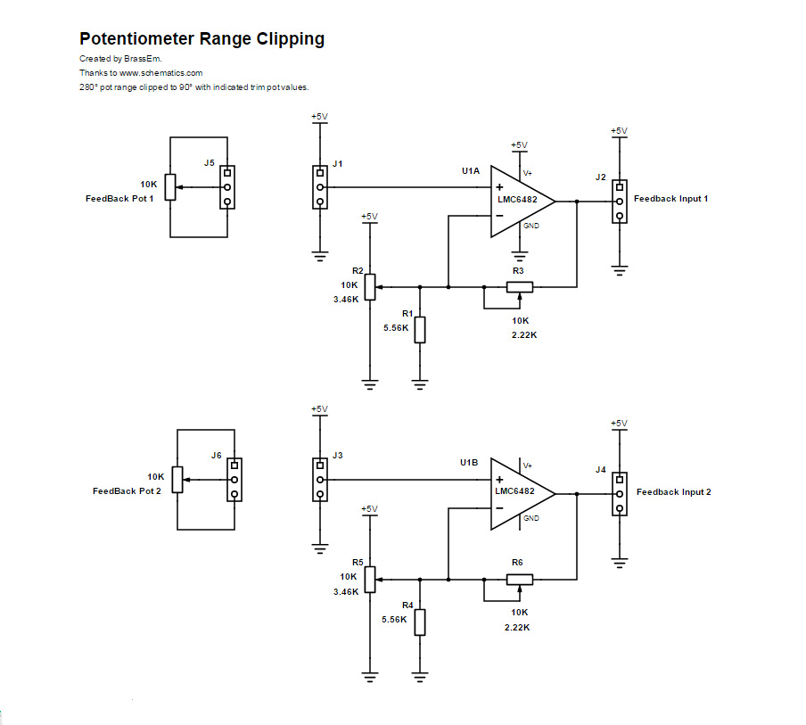
@Milopap An excellent Mod! :thumbup: Would you be kind enough to post the details on the Hat switch assemblies you get from thrustmaster? I am having great difficulty finding a reasonable supplier for Hat switches. @Sokol1_br With the addition of an OP Amp circuit you can modify the pot characteristics no problem. With this example I got full linear pot range from 280° down to 90°. (R3/6 adjusts FSD and R2/5 adjusts Zero. Excess angle is just rail voltages, just need to put mechanical stops in then.)
-
And of course Chris Bergison didn't just leave it at the G-Seat... http://hornetpits.org/index.php?topic=470.0 He also mentions about the seat shaking when firing the A-10 Gun and head shift on G loading on his site. http://bergison.simpit.info/g-seat-faq Something to aspire too. :thumbup:
-
MiG-21 please. (Many thanks for sharing your excellent work!)
-
Excellent work Schredder! You get the best of both worlds with this mod for sure with a grip with lots of switches and true FFB! (Just gotta love the Arduino's! And the X-55 gave itself up for a better life. Would look at putting a 4 way on the C thumb position too.) Do you still have the dimensions for the adaptor at all that you could share? I will be watching this thread eagerly to see how you get on with the beefing up of the motors. (I'm testing with a pololu 33926 driver, 60mm 15W motors and some Actobotics gears. Still assembling.) Well done and thanks for sharing!!!!
-
X-55 Mouse Nipple Modification - PART ONE
BrassEm replied to BrassEm's topic in PC Hardware and Related Software
Just an update on the switch caps. Received the shipment two weeks ago no problems. These caps are hard plastic compared to the VRinsight soft rubberised caps. The ID is 3mm / 0.118" and fit on the C&K straight shank switches okay. (Just need a tab of hot clue to fix in position.) But obviously won't fit the X-55 switches. -
Excellent work spaceraver! Good instructions too. Definitely on the to-do list. Did you find you needed changes in curve settings?
-
The mighty Inta Humar wait patiently on your great works.
-
X-55 Mouse Nipple Modification - PART ONE
BrassEm replied to BrassEm's topic in PC Hardware and Related Software
Nice find. Purchased some to see if they fit. Cheap enough even if I need to drill the hole out a bit. -
X-55 Mouse Nipple Modification - PART ONE
BrassEm replied to BrassEm's topic in PC Hardware and Related Software
G'day Tarvis, Absolutely. It was simply the fact that I could not find a pot suitable without a major rework of the stick. If there is now one available that fits I would seriously look at installing that myself. The resistance was a measured open and hard close. I used all resistance measurements as I needed load values for the circuit. (I will check my notes though to see if I did take voltages at some stage.) -
VRinsight devices (CDUII) in game. VRi2DCSBIOS.exe
BrassEm replied to BrassEm's topic in PC Hardware and Related Software
Those pennies are gold! Thanks for adding the conversion keys.ini file Mighty. It is great to see the original CDU works too! I got your pm and looking forward to expanding the options with this. -
Absolutely stunning work (again) Capt! Also great news about the Beryoza too! Many many thanks for your efforts.
-
Thank you for the rapid response! Having a working model to use really helps. After some trial and error I finally got an SA-15 tunga model into the replays! It all started working right after I renamed the mesh directory from "meshes" to "Meshes"! :doh: Time to start pumping out some SAM models. Thanks again!
-
G'day Vyrtuoz, Brilliant work with this app! I never get tired of watching the generated replays. As an Inta Humar combatant I have tried to update the SAM launcher models without success after following the instructions. (At this stage I cannot even get a box to show.) Would it be possible to post a working obj model to test porting it to other models in tacview as a test/structure reference? (1.3.3 64bit pro)
-
+1 please.