
jackmckay
-
Posts
591 -
Joined
-
Last visited
Content Type
Profiles
Forums
Events
Everything posted by jackmckay
-
 there is some ground on this statement. trees do come as 40m high. what ED could do is do some scalar size randomization like variations in height egg. hilltop smaller valley larger gradually scaling. its plausible. they are either bushes or tall as building and more of them should fill the gap in between. its also valid for vehicles vs roads/railway track size comparison. a assume that in VR those scales do have different effect.
 -
Guys, I am pretty much convinced that F16 is the best recreated module in DCS yet. I wasn't convinced myself till late clean tests but it seems that this module got the most care seen in DCS. There are probably some other issues like pylon/weapon drag still to be fine tuned but its on the right track. compared to others it still leads by spear length. you cant break its wings as seen on other modules egg. i've seen several airshow displays and I personalty find it top tier plane besides rafale, eurofighter and fulcrum. its ground observation, true, but still it rocks in DCS. I've noticed that air brakes are not as effective as I expected egg. and I had some struggle to slow it down on low level so it really manages energy very good by my perspective. most of you complaining should force other modules to come closer to that level even not perfect in overall. the real deal could come in case that someone does some CFD(virtual wind tunnel) vs DCS engine comparison and in that case we could have some top level physics evaluation that experts in field can stand behind. till then, we have no solid ground expect charts from pilot manuals to refer on. here are my 50 cents. have fun.
-
i'll try mr big. dont wanna steal the show ofc. holly cow! f16 actually climbs up! though tweaked at 1% unlimited fuel clean I reached angels 28(8500m) from near deck stop. it looks like there's a hope for 16. i mean, there's excess of 10k lbf(4.5tf) force available what is never going to be rl case ofc and should be replaced by fuel weight to start at tw1. well, 16 is the least to criticize at this point based on this initial test. during mission setup i noticed some other things as numbers don't match official manuals in weight exactly and for comparison mig29s just reached 2/5(3700m) of 16 alt in similar test. some planes cant have pylons removed and its impossible to set wp speed at 0 in ME but only scripted spawn. @BIGNEWY can we have separate topic for independent module performance testing of next airframes? i'd like more people to test tw1+ fighters, since i noticed some numbers in ME dont match official, for a start, and it would be great not to sparse this topic wide but centralized. f16bl50 - ew: 19,200lb/8708kg - eng: General Electric F110 - wt(1/1): 29,500lbf/131.2kN - 1% fuel: 8500m f15c - ew: 28,000lb/12,701kg - eng: Pratt & Whitney F100-PW-220 - wt(1/2): 23,770lbf/105.7kN - 1% fuel: f18c - ew: 23,000 lb (10,433 kg) - eng: General Electric F404-GE-402 - wt(1/2): 17,750lbf/79.0kN - 1% fuel: j11a - ew: 36,112lb/16,380kg - eng: Shenyang WS-10A - wt(1/2): 30,000lbf/132kN - 1% fuel: su27 - ew: 36,112lb/16,380kg - eng: Saturn AL-31F - wt(1/2): 27,600lbf/122.6kN - 1% fuel: mig29s - ew: 24,251lb/11,000kg - eng: Klimov RD-33 - wt (1/2): 18,340lbf/81.58kN - 1% fuel: 3700m mig21bis -ew: ?? - eng: Tumansky R-25-300 - wt (1/1): 15,640lbf/69.58kN(21,800lbf/97.1kN) - 1% fuel: engine shutdown! m2000c - ew: 16,535lb/7,500kg - eng: SNECMA M53-P2 - wt (1/1): 21,400lbf/95.1kN - 1% fuel: + f14, Su33, ajs37, f5, (theese i dont own so .. jf17, f1) TW Test.miz Anyone interested in some more testing? This topic is very crucial btw so any help is welcomed. thank you.
-
well i disagree about fldyn. can you tell at what fuel point the clean airframe reaches t/w ratio over 1 and start to accelerate climb up? name any plane that has enough power and performs so?
-
sticks can be solved by custom predefined curves egg. matching stick product specific. flight dynamics/drag issues can be solved by using extensive CFD prior setting up flight modeling that is tabular in lua files. no need for live hpc farm cfd and even home pc can do it it just takes more time and less accuracy even with open source soft if you like. also for reference, x-plane has primitive cfd in engine and its bmp the best flight modeling out. if rl pilots say it feels some way ed should take that into account BUT the speed feel can be matter of perspective egg. car bumper vs roof cam or zoom level, ALTHOUGH sensor numbers shouldn't lie. if ed needs help, supply us with 3d model and nda to run the tests, comparison and corrections. this should be done long time ago and introduced as mandatory on 3rd party devs as internally. if there's a will there is a way.
-
no its not about some existing DCS mission BUT its actually a custom mission im trying to setup for some logistic two-way runs thus exploring the wp logic. what i found out next is that helis(ch47d) do have some issues with wp like not same as airplanes (all about AIs). i set the mission for planes(c130) on right but helis do not follow same logic. here's updated mission WP_test2z.miz the right setup for planes is: WP0 - takeoff(base1), WP1 - turn point set alt speed (base2), WP2 - ReFuAr (same spot as wp1 aka base2), WP3 - turn point set alt speed (base1), WP4 - ReFuAr (base1) .. switch WP4 to WP0 aka restart circle. conclusion: this works for terrain following in planes but helis somehow quit this principle probably for using FARPS - no wp switching cycle for some reason. the previous example had direct wp logic and worked on short legs (AI alt dependent on leg length?) but when there are cross country leg then AI slams into a ground on some point while closing WP never crossed. i managed to correct that so it works now for long runs on WPs example above. Campaign creators might have this process very useful ofc but im more into scripting of logistics so im planning to play scripted wp switching logic just to make the scenery more alive and adaptable to any changes in wp status.
-
step 1: determine drag vs AoA graph (alpha and beta) up to egg 30deg. step 2: use rude calculator egg.: https://www.omnicalculator.com/physics/drag-equation or just use excell match and correct numbers in lua. simple as that. maybe there's an issue with reynolds numbers here as it appears to be too high, if its implemented. also, there was a overall object-world scale misalignment making objects appear larger than they would in RL. that could also make an impact too. egg. train tracks vs tank width. just to add that t/w ratio is progressive value depending on fuel quant mostly, so there should be a point when plane can stay suspended in air and start to accelerate upwards when above 1 at certain fuel level, case pointing up 90deg. in general, energy management needs some improvements. old story.
-
Noticed some AIs cant avoid terrain and crush. Also, direct WPs cant set altitude without intermediate WP so the real altitude is set by unknown. Strangely, AI flies towards set WP but at 90% leg it turns back and then next round it commits successfully. Talking about perpetual two-way mission. WP_test2x.miz
- 2 replies
-
- 1
-

-
- waypoint loop
- ai
- (and 1 more)
-
AI aircraft modeling and texture poor Quality
jackmckay replied to Vpr987's topic in 3D Modeling for DCS World
https://www.cgtrader.com/3d-models/aircraft/military-aircraft/c-17-globemaster 100bucks royalty free. just saying. -
Countermeasures sounds could be great for visuals. something like here: it looks like there's no louder external sound on chaffs and flares?
-
Fail-Safe Design and Ultimate Load Factor in Military Aircrafts
jackmckay replied to jackmckay's topic in DCS Core Wish List
A good point. Maybe it would be better to go straight to DCS Pope, Mr Grey. This here is on general awareness level. I hope they read it. Well, that is close to impossible. The reasons for that is simple, heads of design or production are not available at this time. those people belong to the history. the only relevant sources are their products and manuals. the relevant data can be reverse engineered or .. by accident stats by type in frame age. fail-safe design had to be implemented. It would be ultimately disrespectful not to implement basic military aviation principles. I wonder how DCS decision makers had all data and sources available per module. Im not sure if that is the case. My engineering standpoint claims that modules are too brittle. In DCS it is common feature gradually implemented. Its great feature but needs to be tuned up by extra 20-30%, time dependent and combined with control surface gradual separation as already seen on certain modules. Little animation triggered by numbers, re-tweaked, following some fail safe initial conditions implemented in fresh rolled jet. those things are nasty beasts in RL. that is too much engineering not to be safe to return after first weak point collapses. Initial conditions are way better.
-
Fail-Safe Design and Ultimate Load Factor in Military Aircrafts
jackmckay replied to jackmckay's topic in DCS Core Wish List
RR Viper engine. Foam boots? remember that story. that material war started very early after WW2. Space race was ahead. soviets were first in space. there must be some high end material/FOS story behind. it didn't happen by accident. the legacy of that time had huge impact on aviation and defense industry. booth sides had reliable space tech form 60 onward besides third parties. -
Fail-Safe Design and Ultimate Load Factor in Military Aircrafts
jackmckay replied to jackmckay's topic in DCS Core Wish List
Even if it is 1.5 as bare minimum it still does not come after 3 sec in constant linear peak force applied. And that should be counted on end of airframe lifetime, under the condition that regular maintenance and inspection was applied. New fresh have 2, at least, just for the fatigue compensation reserve calculated prior serial production. also no one would expect any pilot to stay out of LOC on 18G for 3 sec. if you were given a task to profile structural reinforcements in airframe, and if you stick to regulatory body guidelines, you wont be given certification of airworthiness unless you comply to that rules. I said before, the max stress allowed in reports is 2/3rd of material Yield, 50% reserve to max Yield and 30% on top till ultimate strength point. further then you get excess strain elongation reaching breaking point that depends on applied stress time factor. simple as that. the airframe material has to be highly elastic not brittle and that's why there is an excess wing flex and plastic deformation observed prior catastrophic breaking point. even the choice for materials on critical points is to be selected in high elastic, like steel or titanium if heat is applied. What else has to be conclusive? I'm revealing you the practice of profession and common material behavior. If you want to confront metallurgy principles and regulative bodies practices I have nothing against that. Except no regulatory body will accept lowest criteria then said especially in aviation since the price of product is VIP factor besides safety concern. I don't understand your point. If you think its Ok as now, that is your standpoint, I respect that, but as a chief of production I wouldn't ever sign that paper with your criteria. -
Fail-Safe Design and Ultimate Load Factor in Military Aircrafts
jackmckay replied to jackmckay's topic in DCS Core Wish List
Well, I can not confirm nor deny that soviet FOS state. That is what I heard from mouth of my material science professor on college who had some insights on that side. We can leave that on speculation level. But there is one historical reference that could be taken into account - the IL2. That plane was well known for rigidness and battle endurance as a proof of structural strength concept and was produced in large numbers IIRC. Also when Yak3 La5 Mig3 are compared to P39 Aircobra those had obvious differences, and based on that time comparison, things on FOS side could be at least equal to western approach, regardless of combat performance and efficiency, cos booth sides exchanged technologies in that time. How things later developed stays on speculation level but one thing is sure, FOS are taken very seriously into account. Wing flex is derived elastic safety principle and it is very hard or nearly impossible to snap the wings just by overriding G limitations by 50%. Suffering some wing/fuselage deformation prior disintegration occurs above that number. From my knowledge that critical factor should be at least and above FOS 2 and above 3 second interval. At current state in DCS this occurs bellow FOS 1.5 and instantly. This correction should be universal at least as common ground for all modules regardless of origin. Changing that limitation in DCS should be trivial and if more consultation with other structural engineers is needed, it should be also easy to confirm that design rule worldwide as basic principle in aviation. -
Fail-Safe Design and Ultimate Load Factor in Military Aircrafts
jackmckay replied to jackmckay's topic in DCS Core Wish List
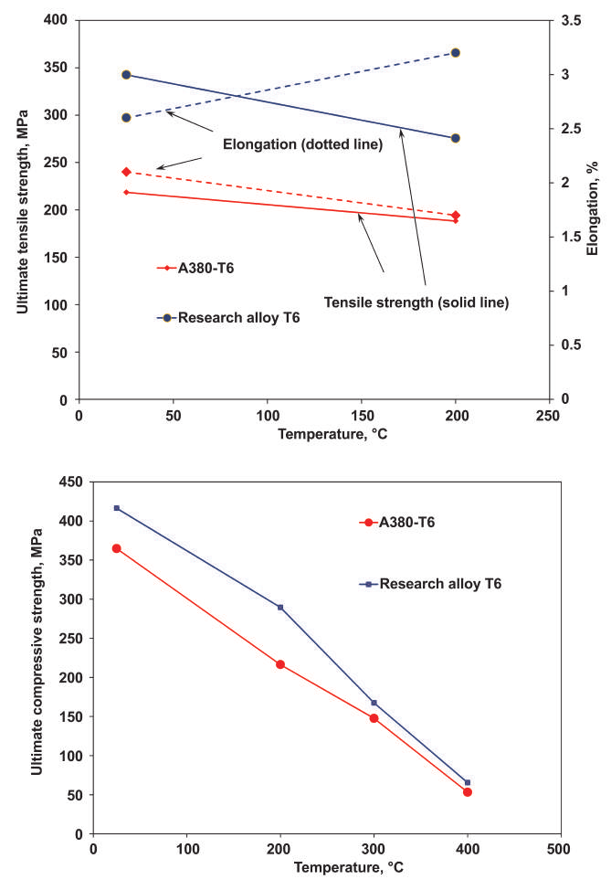
Well, if you intend to design a vessel for colder areas, -60 deg C etc, you need to take into account that materials in cold weather become brittle so to counter this phenomenon you must make your design more elastic to compensate temperature induced brittleness and usually thicker, heavier overall design. that also increases FOS - a lot. So go from -60 on the deck, climb up to ceeling and go mach 3 to heat skin on 1200 deg and come back and settle in -60, then consider the internal stress material has to handle not to develop fatigue induced micro fractures. That is a one tough job and that is why supersonic designs for colder areas require even bigger FOS. that is why, based by my knowledge, soviet design uses UL FOS of 2.5 and in some cases even 4.0 IIRC. Blended wing design is also another feature that further increases FOS. All material strength specification is tested in room temperature at 20-25deg C. That is the starting point. Designers must choose work envelope and the more extreme envelope is, the more radical approach it requires. -
Fail-Safe Design and Ultimate Load Factor in Military Aircrafts
jackmckay replied to jackmckay's topic in DCS Core Wish List
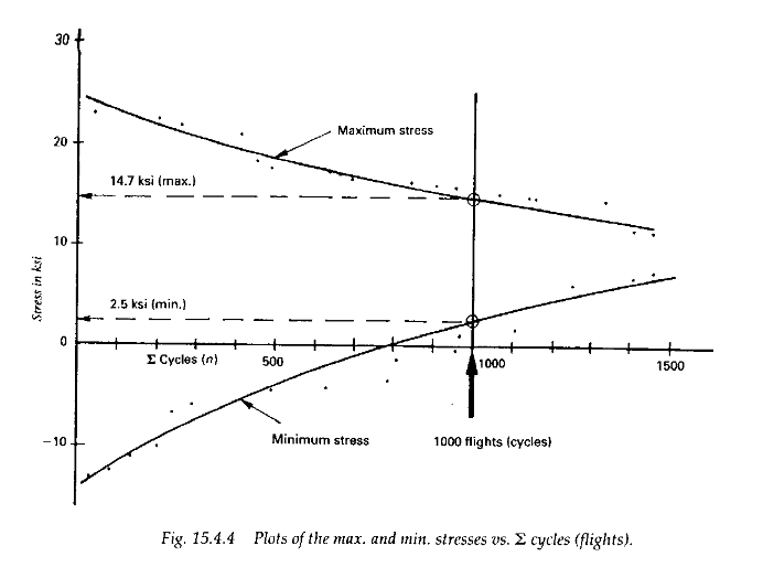
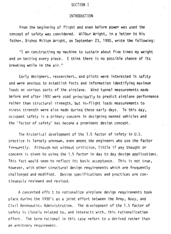
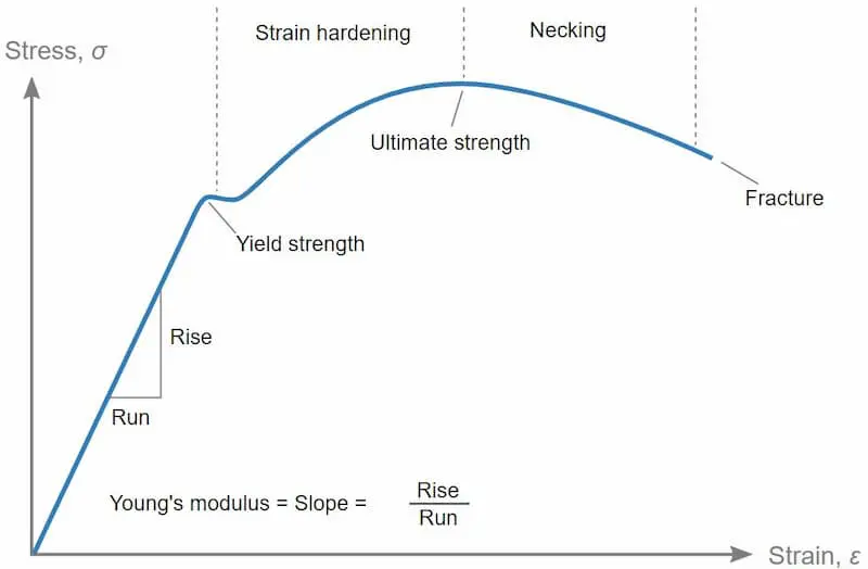
It is report from that time BUT the 1.5 FOS is set early in 30s. FACTOR OF SAFETY - USAF DESIGN PRACTICE Section I This is from era when fatigue assessments were not executed. As much as practice I encounter during my work on structural assessments my limit is set to 2/3 of material Yield strength. ..and this is evolution of fatigue assessments starting from mid 50s. I also stroke, supersonics do have more rigid criteria. On upper stress-strain graph, the difference between Yield and Ultimate strength is roughly 20-30% in favor of Ultimate. That is the way industry deals with this issues and that is the way it is and was for a long time.
-
Fail-Safe Design and Ultimate Load Factor in Military Aircrafts
jackmckay replied to jackmckay's topic in DCS Core Wish List
No answer to that. I'll just keep that aside. So where would you place those airframes in time period or working hours. some 50% lifespan? And what IF time set in mission is exact year of production rollout of unit? Does that mean FOS will be higher? -
Fail-Safe Design and Ultimate Load Factor in Military Aircrafts
jackmckay replied to jackmckay's topic in DCS Core Wish List
1.5 FOS for 3 secs WITHOUT FAILURE. Quote: AGARD REPORT 815 Loads and Requirements for Military Aircraft, Page 14-2. So, FOS of 1.5 is just beginning of trouble for conventional airframes. Supersonics do even perform better in subsonic regime. So take 1.2 FOS initial limit load criteria and multiply by 1.5 ultimate load criteria it goes to 1.8 WITHOUT deformation. Entering plastic zone of strength of specific material will give extra range for catastrophic failure. So FOS 2 is bare minimum for wing separation. What kind of hard data you need to be convinced? Note temperature affected degradation of strength. Keep in mind that supersonic skin is hot and still has to comply strength criteria given.
-
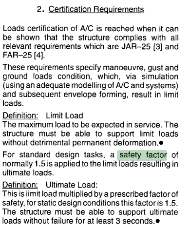
Hi everybody, this topic is intended to clear out some misinterpretation regarding structural strength of simulated airframes here in DCS. During my evaluation and testing of simulated modules I have encountered certain damage model behavior that I found not to be inline with industry specifications and standards, historically and current, respectively in cases of ultimate load excess leading to catastrophic failure on wing structure, partially or in full. As an examples, I point to the occurrences of catastrophic wing disintegration in case of F14, F5, JAS37, MiG21, Su27, J11, Su33 etc. in cases of exceeding nominal limitations given in pilot manuals that occur instantly without prior warnings. My professional background covers field of structural evaluations of mechanical structures in high load conditions with application of crucial factor of safety that is applied on high stress elements of design with respect to fatigue impact on strength degradation over the life span of any high risk mechanical construction that aims to preserve design itself as lives of operators involved. Being involved in such evaluations, I find factor of safety the most important element of design that ensures design itself to be safe even after exceeding defined limitations in user manual in certain conditions. Thus, I will give some brief insights on allowed ranges and consequences of exceeding limitations not stated in manuals. At first, the observed behavior of named modules do not represent real life performance. The initial state of fresh spawned module is projected to be factory rolled state, meaning that there is a minimal work hours accumulated on airframe, theoretically. That implies that the state of structure is at peak strength without any developed structural imperfections and potential seeds of catastrophic failures. The most important structural degradation comes from fatigue induced cracks that are initiated and developed during life span of airframe within work envelope with higher expectancy towards end of life. In practice, that means that initial strength of airframe is, based on fatique evaluation, multiplied in such manner that, within nominal operational limits, able to withstand forces and moments induced on critical elements that keep the design safe on point of reaching end of design lifespan. Initial design safety factor is, founded by FAR, in range of 1.5 FOS(Factor of Safety) for civil aviation projects. Keep in mind that civil aviation designs are not expected to withstand battle damage of any kind but only environmental threats that include rough weather, turbulence and stress cycles induced mostly by landing shocks. Thus, military aviation projects are designed in such way that is mandatory to expect higher values of structural loads and performance limitation impact. As stated by FAR, as historical reference, in practice, that would imply that 9G civilian aircraft is safe to withstand 13.5G ultimate load stress without entering plastic, permanent, deformation of geometry. The ultimate load criteria is to be satisfied in time frame of not more than 3 seconds without plastic deformation assuring the geometry of airframe to return to initial state. That observation is based by FAR, simplified for initial reference. The MIL standards are product manufacturer's specific and are not standardized globally. Those designs do imply structural strength requirements that that exceed civil aviation in many areas simply because of nature of design and operative environment. So, this post is mostly intended to Module Developers, booth to ED and subcontractors, to revise the state of catastrophic failure occurrence in their modules as those practices do not reflect the nature of design they try to accurately replicate in DCS. If referring to pilot manuals, those limitations are intended to preserve airframe in full life cycle span, which means that initial state of fresh airframe is, based by fatigue evaluation, at least in 3-5 FOS range. Taking the lowest state into account, fresh 9G airframe should be able to withstand 27Gs without inducing structural catastrophic failure as wing separation is by nature. Nevertheless, this number might appear overrated but the industry does prove this to be the case as this is basic fatigue requirement and those same fatigue evaluations are expedited in at least the double lifespan working cycles. During that evaluation every weak spot is evaluated and reinforced to compensate possibility of occurrences of cracks that might lead to most undesired outcome. Keep in mind that military airframes, intended to be operational at high mach numbers, do have additional scopes of concern as thermal impact on weakening of structure, density fluctuation in airstream, as much as raw size of airframe aggregates bending moments on wingbox that grow exponentially in respect to length of wing against wing root chord length. My conclusive standpoint is that all involved should redefine the limitations on airframe structure and allow higher margin of safety that should be applied on simulated modules in addition to safety limitations extracted from pilot manuals. The most ideal presentation of structural failure should be presented in a way that, in cases of exceeding nominal limitations, pilot should be warned of incoming catastrophic failure in progressive manner starting from indicative sound (bumps and twists), rivet/bolt loosing and popup(damage module texture), control surface/flap separation (su25T example), permanent plastic deformation (extracted from wing flex feature) with aerodynamic performance degradation and ultimately wing/control surface separation leading to catastrophic event as loss of wing or portion of wing structure is. By rule of thumb the minimal FOS should be around 2 meaning that fresh 9G certified airframe should have to be subjected to at least 18G of force for catastrophic failure to occur and progressive cycle of damage should occur at FOS of 1.5 starting form 13.5G on referenced airframe above 3 second load condition. Thank you for your time. I do expect the corrections of this behavior to be accepted and implemented on future updates based on tools and methods available, but for a start, limitations should be set at FOS of 1.5 without entering permanent deformation on lift surfaces. Regards, J.
- 17 replies
-
- 1
-

-
- structural limits
- design
- (and 2 more)
-
Its finally playable. Just that. Ready for some hard core missions now.
-
Electronic War Jamming Script V2.0
jackmckay replied to ESAc_matador's topic in Scripting Tips, Tricks & Issues
im not that old in lua too, but yes, uncomment that line and check dcs log for extra message lines. for short code test you need debug console like dcs bios, witchcraft or dcs eclipse debugger or something, just to check if the table has client module inside to work properly. then upon death of unit those table should be purged of unnecessary clients. it takes some skill but its not that hard to code it. if you uncomment that line in script, on around line 69 that has tableShow, dcs.log will show jamming units in log lines so you can check who is using script. -
How high/fast can you go in Viper - challenge
jackmckay replied to jackmckay's topic in DCS: F-16C Viper
you got to kidding me. that's insane. Angels 94? Is that at supercold weather at bottom start? -
QC: I think its about MP server we are playing on. I was referring to Enigma server.
-
I'm having a same issue on latest updates. What I noticed is when I press game Pause my GPU utilization goes up to 100% from running at 60% in game. That is a bit odd. I also tried lowering settings and vsync OFF etc. but the major performance impact was visible by turning fullscreen OFF which helped a bit. Talking about Causacus scenery. Syria runs better for some reason in GPU utilization in windowed mode too. Matching fps to monitor is obviously the best option and the worst thing out there is when game performance in pair with headtracker downgrades your ability to spot enemy planes in combat. That is a real handicap here.
-
fixed F-86 Show me your Gun skills in a short track replay
jackmckay replied to BIGNEWY's topic in Bugs and Problems
Don't wanna spoil the party BUT.. there is a strange behavior on F86 performance in overall. One thing I noticed, away from sabre pilot individual marksmanship skill, is that sabre does turn exceptionally well and doesn't bleed much energy in turns, in fact it builds it quite rapidly in comparison to Mig21. Even on st2 AB in 21 slight dive, it is very hard or impossible to outrun that little bird. in comparison to 21 wing high G structural damage, which I doubt to be that easy, 86 doesn't appear to have that issue even having larger wingspan and shorter root chord and it also looks like isn't affected by blackout limitations too. SO, either 86 looks to good or 21 appears too bad in energy bleed and recovery. I feel that that strange performance might be inspected at this point. Tnx.