
Viper1970
-
Posts
2290 -
Joined
-
Last visited
Content Type
Profiles
Forums
Events
Everything posted by Viper1970
-
Universal military aircraft homecockpit project
Viper1970 replied to Viper1970's topic in Home Cockpits
Yes you are right! I totally missed this option during the 3d construction . I hope it works precise enough for the turbine rpm. Normaly you rarely use it after the start up. I also have no mechanical idle stop. I will do this function with a simple, but fully programable digital button. Not realistic and I thought about a mechanical stop, but the way I constructed my collective with changeable hats, making a mechanical stop is to complex and the stop mechanism would be to chunky. -
Universal military aircraft homecockpit project
Viper1970 replied to Viper1970's topic in Home Cockpits
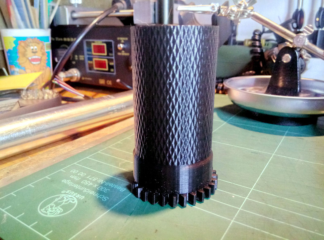
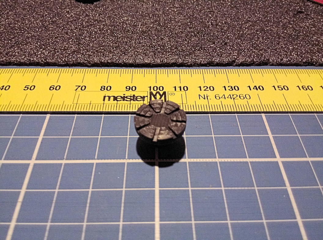
Thank you! Mostly the good results in printing are a matter of time. This twist-grip is 40mm x 80mm in dimension and a relatively simple shape concerning the print itself. There is nothing what makes the printer doing long travels or anything else that is very complex and it took nearly 10 hours with a layer-height of 0.12mm, an lined infill set to 60%, and a print speed of 50mm/s to finish it. On the other side there is for sure a lot of time saved at the reworks. It's mostly ready for painting. My craftsmanship is far away from perfect . I have searched in some model maker forums for a good way to do paint works during the cold weather season without using aerosol cans or a airbrush gun inside the flat. There are some guys that do paint works with a simple brush that are really mind-blowing! I have tried it with all the tipps and tricks they told me, but my stuff still looks like rubish. I have to wait until summer and have to use spray paint for all the painting of the bigger surfaces at the parts. My solder works are also far away from anything good, what makes me angry sometimes. I know that I have done some real good solderings in the past, but now I can't remember this. It's for sure a matter of my disease, but also has to do with missing patience. I want to get this damned dream now finished, after nearly 25 years and three other pits I started. I hope I'm able to do get it done this time, but who knows what new BS the RL brings again. The overall situation is not looking very promising at the moment . -
Universal military aircraft homecockpit project
Viper1970 replied to Viper1970's topic in Home Cockpits
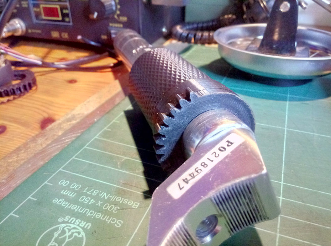
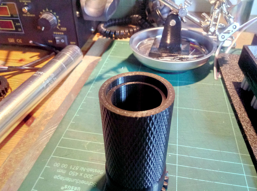
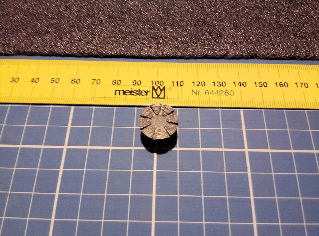
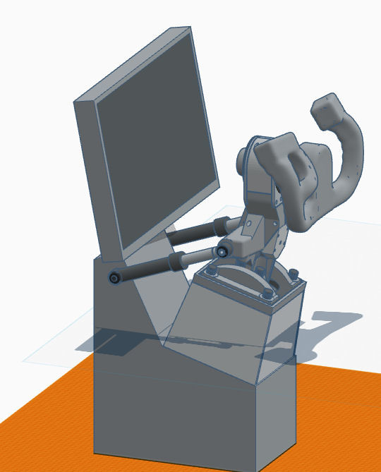
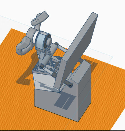
And ready! The second one is just in print... It fits perfectly over the tube from a bike saddle, that I use for my twist-collective and the heads as a base for the mounting. How this should look like if all parts are printed and installed can be seen as 3D models in my thread. I will use nyogel to dampen the twist-grips in the rotation. The gear segment is for a matching gear at the pots I use for the throttles input.
-
Universal military aircraft homecockpit project
Viper1970 replied to Viper1970's topic in Home Cockpits
Just keep in mind that if a part has a lot of cantilevered sections, you maybe have to adjust the temp a bit down and you always have to use supports, even for smaller cantilevered parts of the print. But I made also the experience that the supports are better removeable, if you print with higher temps. It needs some more force to remove them, but its much seldom that you damage the print while removing them, cause the printed part itself is much stronger. But it can take a while to remove the supports, so be patient . -
Universal military aircraft homecockpit project
Viper1970 replied to Viper1970's topic in Home Cockpits
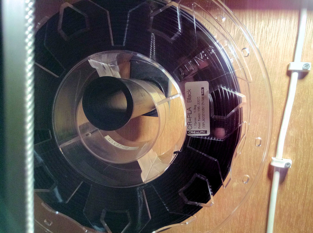
The simple Creality PLA . It was packed three years ago together with my printer, so it was the first one I had experiences with and I'm still happy with it. I have tried a few other cheaper ones, but they were sometimes really bad. So I switched back to it. There are for sure also some better PLA filaments out there, but most of them are more expensive. And it works for me since three years now. P.S: I also tried PETG, but the results aren't as good as with PLA in my case. They are not bad, but PLA prints smoother for me and if I print it with high temps, it's also very, very strong and also good to sand, drill or do any other rework after printing. Edit: The PLA I use for this print:
-
Universal military aircraft homecockpit project
Viper1970 replied to Viper1970's topic in Home Cockpits
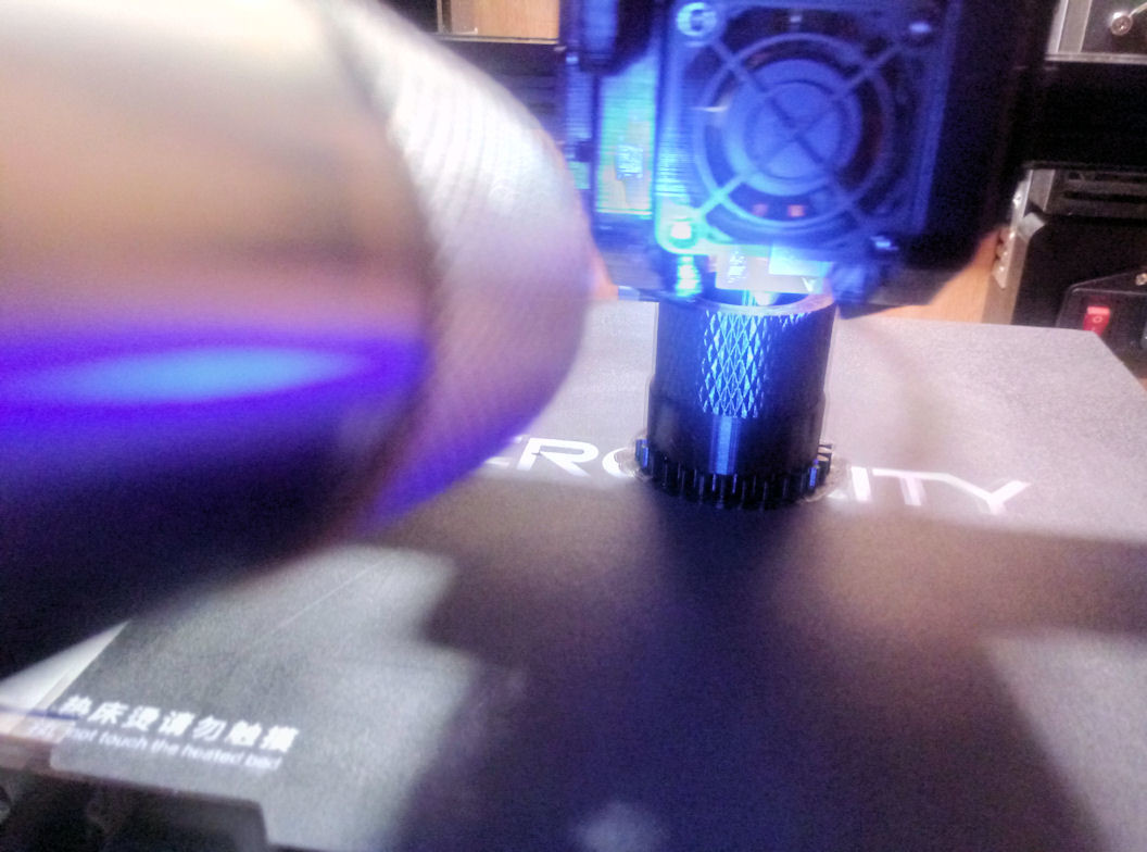
Print in progress . Just doing the first twist-throttle grip of my "universal" collective, which will be used for the Huey's, the Cobra's and the Kiowa. I only change the collective heads here. For the Blackhawk and the Apache this twist-throttle section can be removed. I do my prints in PLA with a very high temp (here I use 235°), cause this gives me the best results in stability, size accuracy and quality of the surface. The corrugated surface of the grip is absolutely clear and detailed.
-
Amazing work! And it's always the same, it starts with something small and then thinking: "Ok, this is nice, but wouldn't it be cool to have this function also? But when I make this, I also wanted to have that....." and suddenly you are in a big project .
-
Universal military aircraft homecockpit project
Viper1970 replied to Viper1970's topic in Home Cockpits
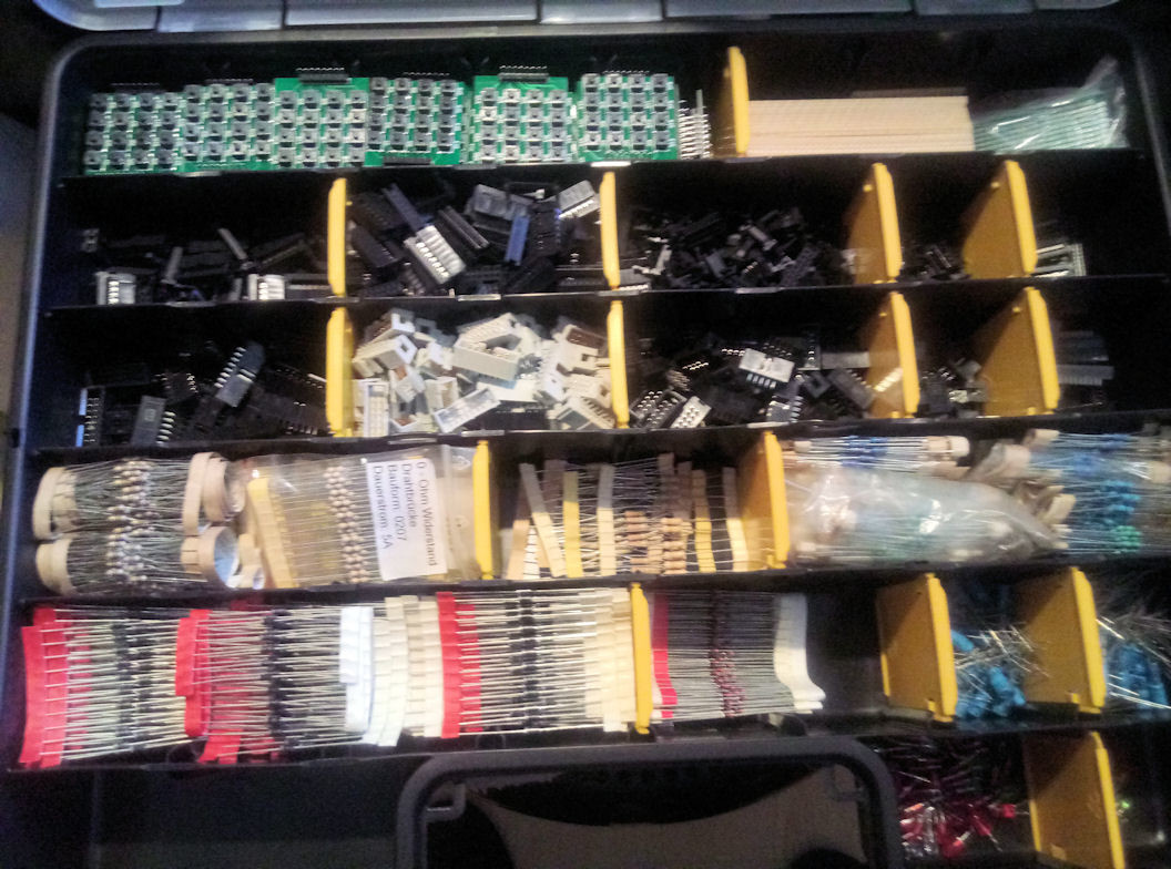
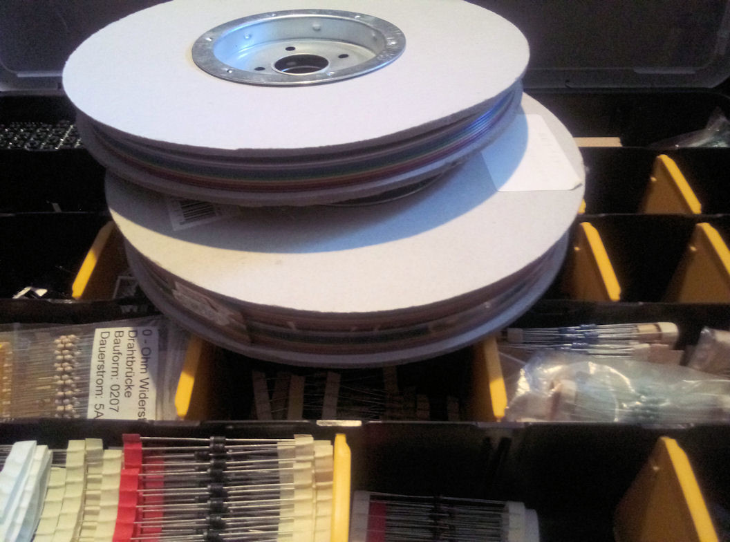
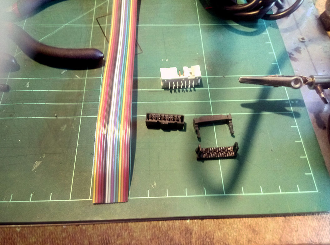
Not much happening at the moment. I still have to print a lot of parts and in the meanwhile I started with the electronics of the command units consoles and the UFC. I wanted to do the connections from the main electronics, which are based inside the UFC, to the little consoles with the use of ribbon cables and matching plugs and sockets (same type as used in computers for eg. the old PATA cables but a little smaller), but the cables I bought do not fit exactly in the cutting clamp of the plugs. I tried it a several times now and I'm always getting a short between some pins. At first I thought I've made mistakes in my matrix circuit, cause there were ghostings while pressing a switch or button, so I resoldered anything and started once again. I also checked all diodes I used to be sure that they are working correctly. It took me hours to identify that the fault is inside the ribbon cable plugs . Although the cables and the plugs are bought together and were sold as compatible, they do not fit exactly inside the cutting clamps. It's so fractional, you didn't even notice it, but it makes a short between some of the wires. I tried it a few times to get the cable exactly matching and 100% retangular inside the plug to prevent a short, but the cables respectively there wires aren't matching exactly to the gaps inside the cutting clamps. After pressing it together there are a few places where the wires have a short. I could buy other cables for sure, but I have not the desire to have the same trouble and must buy new cables over and over again to get really matching ones. The ones I bought are the right ones matching the plug system I use, but either the plugs or the cables are a little bit out of tolerance. So I will use normal cables now and simple SUB-D 15pol connectors. The connecting isn't used much, it's only there to be able to easily dismount the seperate parts from the command unit if something breaks. Just started with the wiring of the matrix part once again : and the old ribbon cable parts I wanted to use . I hope I can still use them. A buddy in another forum told me that they always used a hot gun to get the ribbon stretched, so that it fits exactly into the gaps, preventing a short. I hope this does the trick. I don't want to throw all this aprts away cause at the moment they are really useless. But I also don't want to have predetermined errors in my circuits and have to rework them every time before all is without any electrical shorts. I don't thrust this stuff anymore, as professional and clean it looks on the other side :
-
Universal military aircraft homecockpit project
Viper1970 replied to Viper1970's topic in Home Cockpits
Who needs an SLA printer if you can get things like this with an FDM . As said I'm a lazy guy and dont want to clean my SLA after printing only some few hat caps for a throttle, so I tried it with the FDM and nearly perfect. This is a very small version of a slew hat (most others a bigger). It's used at the F-15E throttle I will convert out of the A-10 throttle (TM Warthog original throttle). I printed with a speed of 25mm/s here, used a temp of only 216° (cause of the slow speed) and used 100% infill. Layer height was set to 0.08mm. Removing the supports isn't easy and you have to do it very carefully. After the removal of the support I used an emery board for fingernails to do the sanding at the remaining asperities.
-
Universal military aircraft homecockpit project
Viper1970 replied to Viper1970's topic in Home Cockpits
Absolutely perfect work here And it looks better as some of my solder-works. I've just seen that I'm not so good in soldering anymore. Getting older is not always an advantage for the hobby . -
-
Universal military aircraft homecockpit project
Viper1970 replied to Viper1970's topic in Home Cockpits
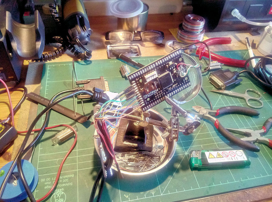
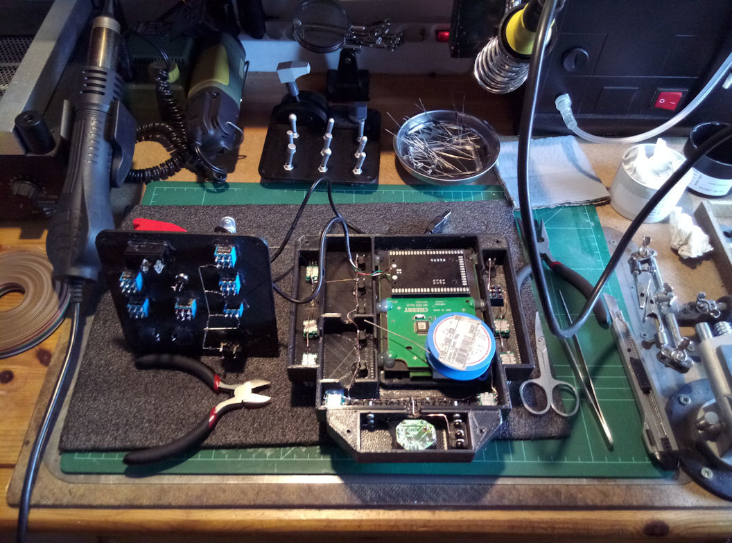
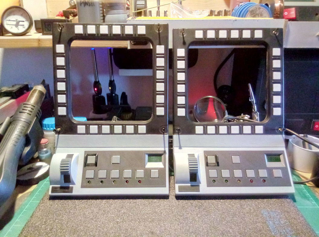
Just started with the electronic part for the UFC and the consoles of the command-unit . Partially a matrix circuit is used here. I do the circuit directly at the console panels and do not use an extra PCB here. In the unit are frames for those side front-consoles in which they can be screwed into and the back is completely closed. All will be connected with plugable cables to the UFC, which has the Pokeys 57U integrated, that controls the UFC and the also side front-consoles. Only the keyboard part of the UFC is using the electronics of a programable Cherry numpad.
-
-
Universal military aircraft homecockpit project
Viper1970 replied to Viper1970's topic in Home Cockpits
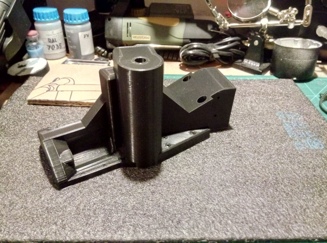
So, all parts for the yoke-extension are printed finally! The bearings fit perfectly (second bearing is missing here, cause it's still integrated in the old yoke I've built for my predecessor pit - I have still to umount this). Nothing is deburred or sanded yet, only the brim and the support is removed. It's just like it is out of the printer. I only used 0.2mm layer height here to save some printing time. The walls, the botton and the top are printed 2mm in width. The infill is cubic and set to 50%. Print-speed was set to 55mm/s (30mm/s for walls). The bed temp was 55° and the nozzle temp 224° (this turn out to be the optimal temp for the PLA that I use at the moment to have a strong layer-adhesion). I have used a 0.5mm nozzle instead of the 0.4mm. This makes not a real difference in detail, but is saving some additional printing time. There aren't any walls on my parts that are more thin than 1-2mm. I will do the same for the HOTAS parts but will use a slower print-speed and a 0.12mm or even a 0.08mm layer height (0.04mm steps are the best fitting for the Ender 3 Pro z-axis stepper). Those parts are very, very strong and have also a nice massive feeling. The forthcoming grip shells will not feel like the metal grips from TM, but for sure better as the most plastic grips do.
-
Universal military aircraft homecockpit project
Viper1970 replied to Viper1970's topic in Home Cockpits
and done. For the com-unit, this is ok. The TFRP and my firts HOTAS I made also a while back for my command unit (similar like the HORI HOTAS I made, but with the use of an old Attack throttle and stick, also with a bunch of programable buttons and switches) I will gift to my son, that he is also able to fly DCS a bit finaly. I have enough equipment for flying and do not need an extra HOTAS for the HTPC, I think. He will have more fun with it.
-
Universal military aircraft homecockpit project
Viper1970 replied to Viper1970's topic in Home Cockpits
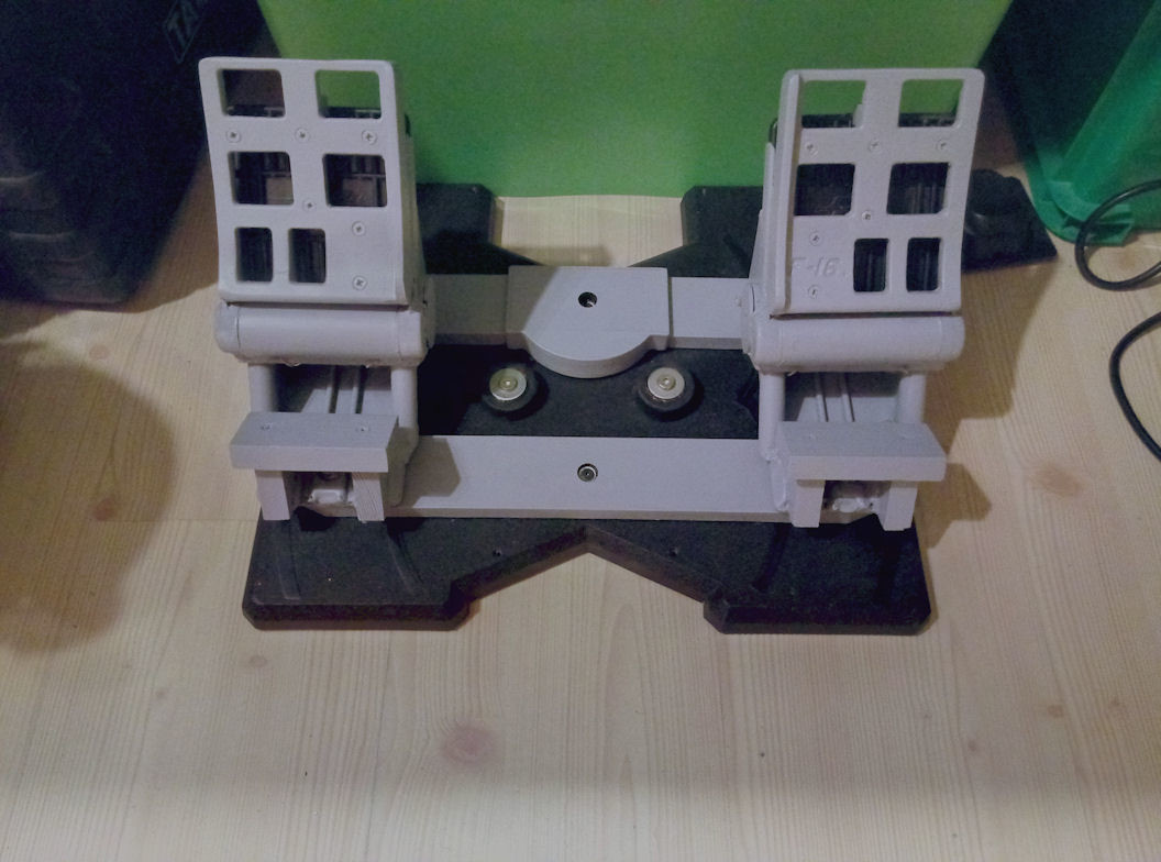
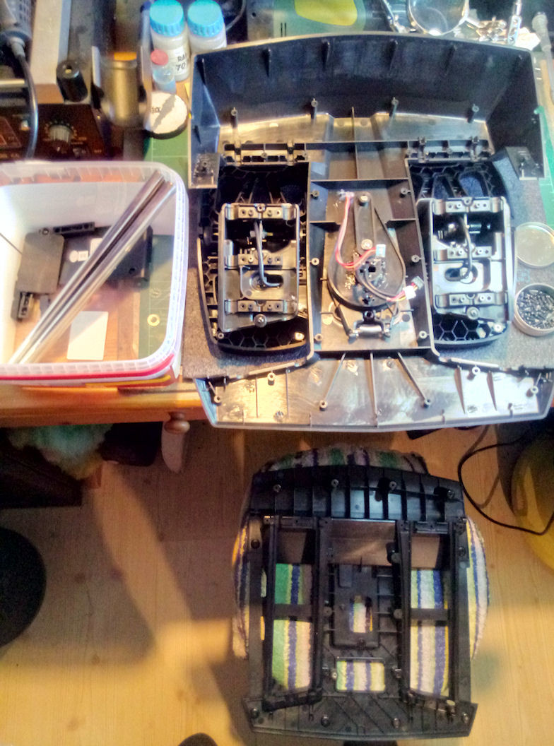
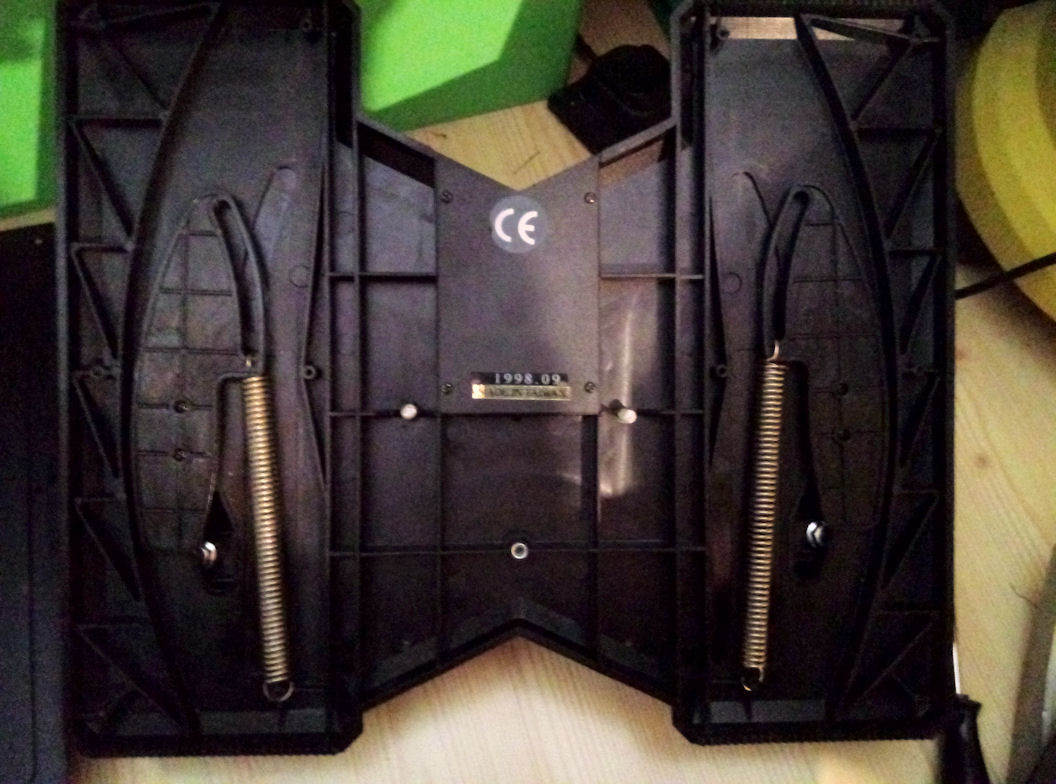
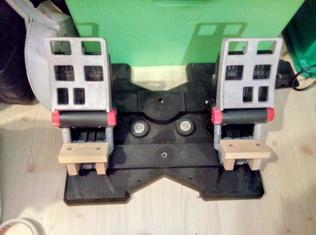
While printing the large parts of the yoke extension, I take a look at the TM TFRP pedals, which I planed to use with the rest of my command unit HOTAS. I never had any kind of joystick, rudder or anything else which was screwed together with such a mass of screws. It's really crazy! . I will cannibailze it's "electronics" (just a simple PCB with cables to the axis connected) and maybe reuse them for any of my selfmade HOTAS at which I use the TWCS electronics, to have three additional axis available. I also think about customizing it a bit and maybe looking for a way to get the pedals a bit wider. There is a mod on Thingiverse, but thats to complex in my opinion. If I do it I, only want to print something "small", to get the pedals a few centimeter apart from each other in wide, but I don't know at the moment if there is an "easy" solution to do this. Finaly it will also be painted grey. If this is is done, all the whole parts of the command unit are completely ready for their mechanical side and also painted. Only the lettering and the satin clear coat must be attached finaly. But this I won't do before the electronics are integrated and fully functional, to still be able to adapt any identification if something must be changed other than the way I planned it until now. I will use only one Pokeys57U card here to make the whole HOTAS functional, including the rudder axis, the stick, the throttle and all the buttons and switches directly on the HOTAS. The whole thing must be one device in the end, so that it can work also with older OS like Windows 98 with my retro simulations. Edit: I rethought the idea of using the TFRP pedals and insted I will use my old modified TM Elite rudder pedals. I have also upgraded them with toe-brakes and a better spring mechanism back those days. The plastics are much more stable as the one of the TFRP and the spring mechanism I made has no center bump. It's absolutely smooth, but also returns very precise back to center. I also had a set of F-16 pedals lying arround, that I now will mount on top of the old pedals and do a bit of dremel work to make them perfectly match in shape. After all the whole thing will be painted in "cockpit-grey". The foot-rests I made cause I have a disease and can not hold my arms or legs levitating for a longer time, even if they are slightly rested on something. I must also make a solution for my sidestick in the pit for this reason. Maybe something similar to the arm-rests like the real aircraft have. The TRP Ican use leaving my heels on the cockpit floor and only put them up for braking. The remaining TFRP will serve for my little HOTAS I use at my HTPC in the living room for funny things like playing SCI-FI simulations or more arcadish stuff .
-
Universal military aircraft homecockpit project
Viper1970 replied to Viper1970's topic in Home Cockpits
End the bottom part of my Yoke extension. The second piece just finished printing. I only put them loose together with a small stripe of doublesided duct tape to see if they fit together. Nothing reworked here and also not did the deburring yet. If finished, this all should look like at the 3D picture. I will mount additional dampers at the yoke wich can be quickly removed with knurled nuts from the rotation-point at the base.
-
Universal military aircraft homecockpit project
Viper1970 replied to Viper1970's topic in Home Cockpits
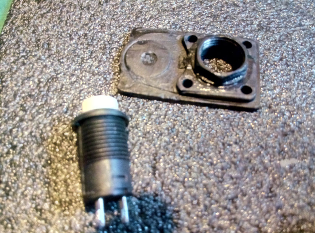
I know that some guys here use original OTTO-buttons and switches, but I want all my stuff affordable. The buttons not top notch, but far better as the original ones. They do not wobble arround and have the same size as the one TM used for their Viper and Hornet grips. The thumb-wheel-switch makes no sense as an axis if you use TM electronics, so I also changed this one. For me it also feels a lot better this way and it's a bit bigger as the original. I will do a dual stage trigger as well, but have to construct a mount for the switches before I can integrate it again, cause the original PCB's did also serve as an attachment for some of the mechanics. -
Noch ein Urgestein der Simulation! Seit Anfang der 90er bin ich auch dabei.
-
Universal military aircraft homecockpit project
Viper1970 replied to Viper1970's topic in Home Cockpits
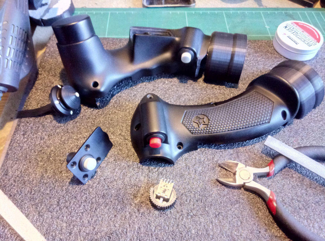
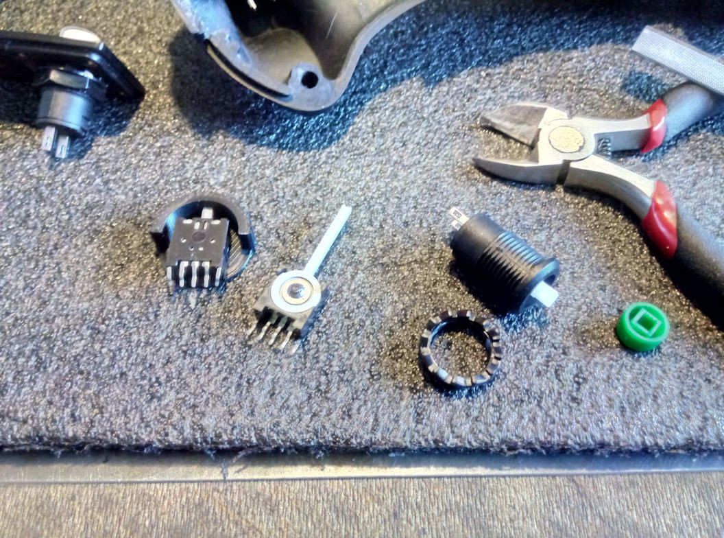
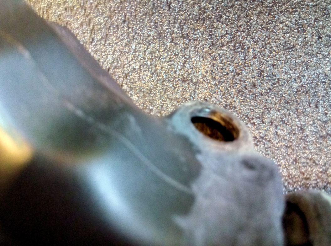
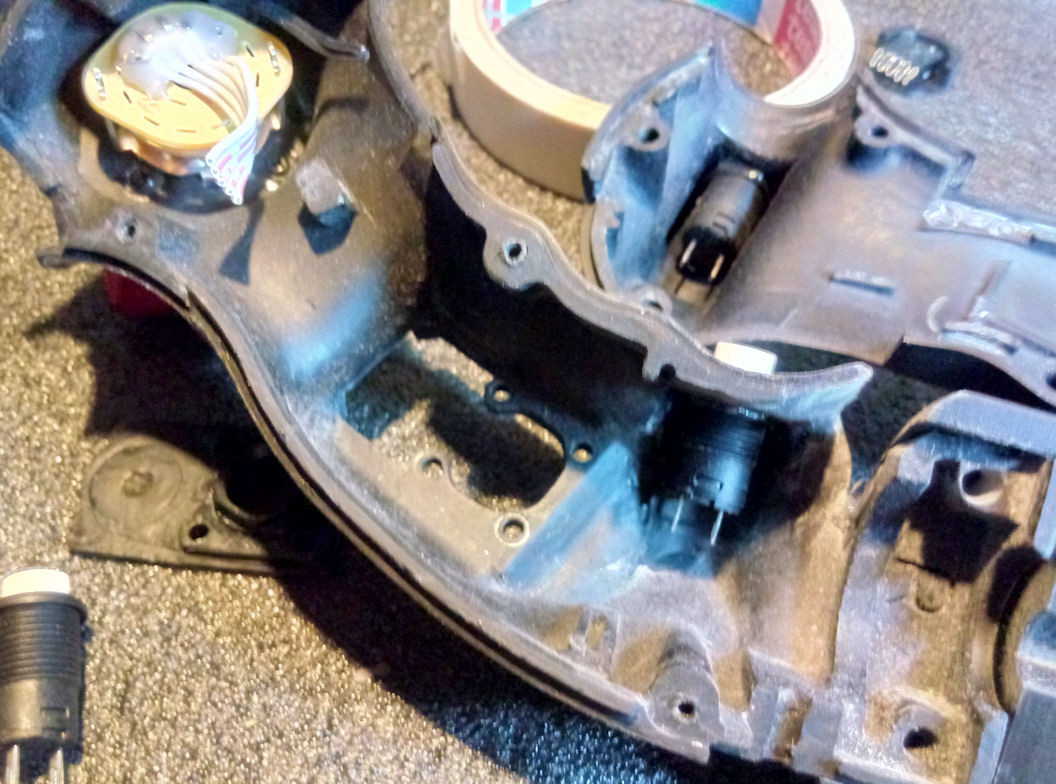
While the second part of my yoke extension is printing, I did a closer look at the F-14B grip again. I removed all original electronics and changed the ugly buttons with some more real looking ones. Their mounting nut fits perfectly in the original holes of the Virpil buttons. I only sanded the friction noses on them down, to have a plain surface. This mounting ring/nut will be glued to the grip-shell. I did also remove the pot at the thumb wheel and changed it with a rotatable, springloaded microswitch, I printed my own cap for. Nothing is ready yet and the whole grip, with exception of the weapon selector part, will also be spray painted in satin black. The lower buttons themselves will be dark grey and the weapon release button red painted again. I also have to glue the socket parts to the grip shells, drill the right holes in them and fill the gap where the paddle switch was placed with epoxy and sand this part to be one shape. The painting of the buttons is easy, cause I can remove the cap of the button, do a little sanding with use of my lathe and after this can spray paint all the button-caps with matching colors. There is also the option with those buttons to print own special caps if needed. and some more detail. The mounting-rings/nuts of the buttons are fully glued in and a part of the shell now. You can always solder the button off and scew it out. The microswitch with the thump wheel button is also integrated now. Hat to dremel the square-hole a bit bigger.
-
Welche zukünftigen Module würdet Ihr Euch wünschen?
Viper1970 replied to Noodleholz's topic in Deutsch
Also insgesamt bin ich sehr zufrieden mit den Modulen die wir schon haben und was bereits angekündigt noch kommen wird. Wenn dann irgendwann die F-4, F-8, A-7E und A-6E auch noch da sind bin ich super glücklich . Es gäbe natürlich noch etliches was ich auch sofort kaufen würde z.B. (A-1, F-105, F-111, F-117 usw.), aber was ich wirklich noch schmerzlich vermisse ist meine heißgeliebte AH-1F Cobra (und hoffentlich auch diese Version - oder dann gleich ein Doppelpack AH-1F & AH-1W) . -
Universal military aircraft homecockpit project
Viper1970 replied to Viper1970's topic in Home Cockpits
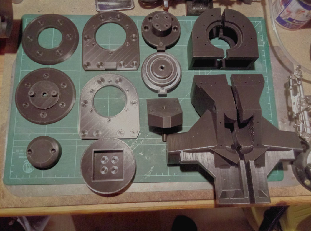
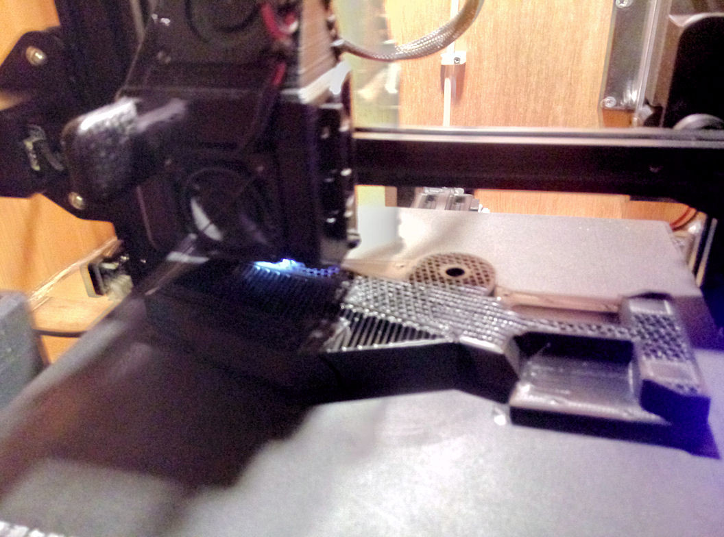
The command unit parts are all ready and painted now (with excepition of the rudder pedals), so I can integrate the electronics. Meanwhile my printer runs 24/7 to print all my HOTAS parts for the pit. I will finish all the bases at first (center base with the different extensions and the collective base) and after those parts are done and adjusted, I will begin to print all the HOTAS grips. I hope I can get most of this finished until the end of April to be able to start with the spray filler and spray painting. I'm not so excited of some of the resiults with the brush painting I did at my com-unit parts, but I want to have them ready at least so I can do a bit of gaming in the meanwhile. The pit will take a longer time to get finished. At the moment the first part of the yoke-extension is printing. It takes 29 hours and 330g of filament. I print all parts very strong. At the end the yoke extension alone will weight arround 1Kg (4 parts and two big ball bearings). Print in work . I use a 0.2mm layer height here, cause it's only an extension (don't want to know how long this would take with 0.1mm ). The infill is set to 50% and I use a cubic infill, that makes it very strong at these settings. The wall thickness and the bottom and the top are set to 2mm. Bad photo, but the printer is moving . and ready
-
Universal military aircraft homecockpit project
Viper1970 replied to Viper1970's topic in Home Cockpits
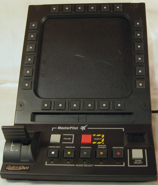
Reworked the old Masterpilots a bit. And yes, they are still working once programmed, even with W10/11 . Original: and mine now for the com-unit:
-
something other
-
Also a very cool version of Dear Mr. Fantasy. What a guitar, I love it