sharkfin61
-
Posts
422 -
Joined
-
Last visited
Content Type
Profiles
Forums
Events
Everything posted by sharkfin61
-

Looking for a Warthog stick extension..
sharkfin61 replied to sharkfin61's topic in 3D Printing for DCS
Received it yesterday, test-installed fitted lika a glove. Now next will be the AVA. 1a quality for now, as I cannot test it in flight. Very pleasant wiring and materials. Regarding the price tag, the 52 GBP ebay item ended as a ~100€ buy, due to taxes and shipping (just as an info for other buyers). Again, thank you @Nightdare and @_Hoss for pointing me to it. -
Looking for a Warthog stick extension..
sharkfin61 replied to sharkfin61's topic in 3D Printing for DCS
Thanks to both of you Nightdare and _Hoss. @Nightdare, if I had it manufactured as a single product by my needs, I'm sure, I would cost me a fortune over here in ole' Europe (expec. with the "wonderful" tarrifs nowadays ). But a very interesting website, indeed. @_HossUnfortunately the Thrustmaster extensions are not really what I am looking for. I already fly with a straight 4" extension from Sahaii, but I had to bring the Warthog base to level with a plastic tube. On the other hand, the long extensioon seems to be rather for choppers. Your's _Hoss looks very close to what I'm looking for (200mm curved). Will take my stroll on ebay now. -
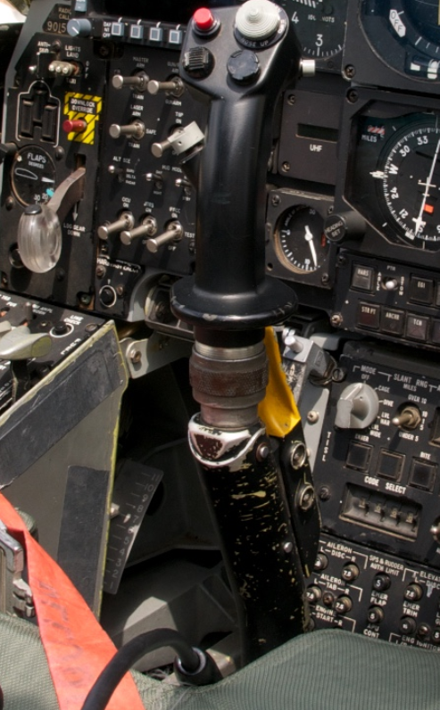
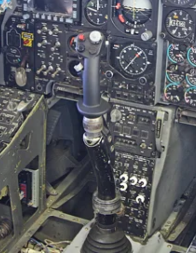
Did anyone stumble upon a Warthog stick extension, resembling the "real" shape of the A-10C's controls, to fit on the TM AVA base? Doesn't matter if 3D printed or made from metal. Thank you. (picture kindly taken from: https://de.m.wikipedia.org/wiki/Datei:Fairchild_Republic_A-10A_Thunderbolt_II_cockpit_2_USAF.jpg)null and: https://www.instructables.com/Start-off-with-a-fresh-Poster-Boards/ null

-
Has anyone found some brass inserts for 3D printed knobs?
sharkfin61 replied to sharkfin61's topic in 3D Printing for DCS
Update: I received the last 29 inserts after almost half a year, so, I can only recommend that seller if youre not really in a hurry (well I wasn't completelety his fault, but after he finally received a working batch of the inserts with the holes drilles and threaded, he simply forgot to sen them to me) -
@JohnnyChicago Have you already completed your RS485 installation? (I'm still hesitating...) May I ask you, how powerful your PSU is?
-
Zwar nicht die exakt Antwort auf Deine Frage (Komprimierung), aber was würdest Du von einem Auslagern der Terrain-Daten auf eine zweite Festplatte (Verknüpfung mit DCS per "hardlink") halten? Dann könntest Du die Installation auf der 870er EVO lasssen, nur die Theater auslagern. Hier wird's beschrieben, bei mir funktionierts gut.
-
Just as a reminder or hint for the ones whose 3d-printers slicers can't cope with .sdlprt files from Solidworks (like my orca or bambulab slicers): Instead of trying to get a demo/ degraded license for the main program, go for the e-drawings pro, a 3d viewer from Solidworks, with which you can save the .sldprt files in a .stl format. number 4 in the list Or, even better for the ones, who are willing to learn Solidworks from scratch, buy a makers license for 24 USD/ year : https://www.solidworks.com/solution/solidworks-makers
-
- 3
-

-
@No1sonuk Ahh, very pleased to hear that.
-
@Gareth Barry just yesterday I looked up solutions for a similarr problem, however, I'm not as far as you are. I was trying to develop a wireing plan for my pit. Now, to get to the point, regarding the 5V supply of the Aduinos (you need in fact 7V per unit), I read, when you connectz the powerjack, you cant have the USB connected, Thus making your forwarding if inputs to the PC quiet difficult. If anyone knows better and can tell me the opposite, please do. What I have done so far to supply my hardware are powered usb3 hubs (RSH hub ). But as I said, I haven't the expirience with a fair amount of arduinos, only with 2 so far. They were working together with TM HOTAS, pedals, UFC, TIR, headset, 2 TM MFD's a ,CDU, a wireless mouse, all on USB ports.
-
Hey @lesthegrngo, regarding your "painted 3D printed covers", how did you manage to fixate them on the toggle levers? Epoxy glue? Or are these expensive toggles, from which you can screw off the lever caps?
-
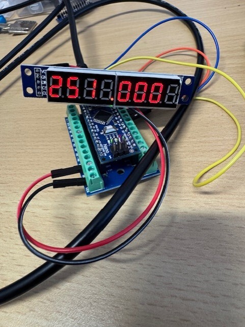
@Vinc_Vega you are a legend! The only thing I had to do is to shift also the "A10c" from @CraigS code (to see if the display is working on start-up) to the right position. //SECOND - 8 DIGIT 7 SEGMENT DISPLAY - UHF RADIO (CODE) MAX7219 BOOT CODE WHILST AWAITING SOCAT DATA STREAM // lc2.setChar(0,6,'A',false); lc2.setChar(0,5,'1',false); lc2.setChar(0,4,'0',false); lc2.setChar(0,2,'c',false);
-
Thank you @Kenpilot for publishing your work and also a huge "thank you" to every helping hand out there. I hope a lot of other simmers will chime in and help the upcoming (and existing) cockpit builders in their efforts. I know, some will see it different, and in fact it surely is important to stick your nose inside the deep hollow of programming and writing code. But on the other hand, it might help people, who are about to give up their dream to built a working cockpit or desk-pit, to find back their way into the seat, flying once again and enjoy the work they have done and therefore, keep the cockpit building community alive. (a lot of words and wishes for 04:50 a.m.).
- 1 reply
-
- 2
-
-
Thank you, Vinc! So, as I understand, the number in square brackets is the position of the digit in the array?! My saviour (as always) Will try tomorrow, reporting back.
-
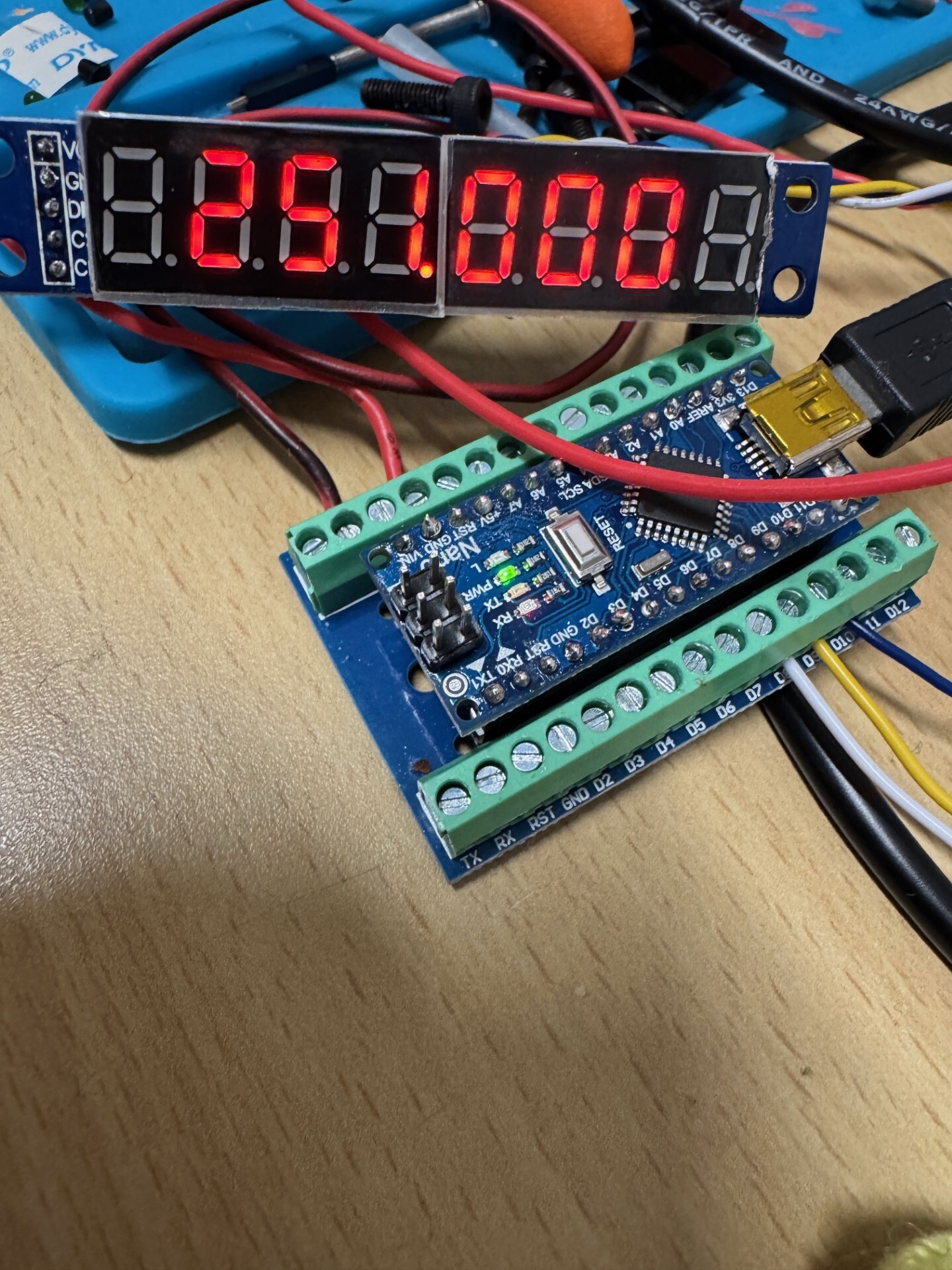
Fellow simmers, I starting to climb walls because I can't figure out how to shift the numbers in a 8 digit 7segment lcd into position. due to the cutout in my UHF panel, I have to have the numbers on position _234(.)567_ . Lcd is a 3461-AS array with a MAX7219 IC. I tried it with @CraigS (mysimpit.co.uk) code like this: //SECOND - 8 DIGIT 7 SEGMENT DISPLAY - UHF RADIO (CODE) void onUhfFrequencyChange(char* newValue) { lc2.setChar(0,7,newValue[0],false); lc2.setChar(0,6,newValue[1],false); lc2.setChar(0,5,newValue[2],false); lc2.setChar(0,4,newValue[3],true); lc2.setChar(0,3,newValue[4],false); lc2.setChar(0,2,newValue[5],false); lc2.setChar(0,1,newValue[6],false); } DcsBios::StringBuffer<7> uhfFrequencyBuffer(0x1180, onUhfFrequencyChange); and I got this: Is there codewise something I can do, to shift each of the first 3 numbers one position to the right?
-
Rotary Encoder W/Switch, LED and Arduino Help Please
sharkfin61 replied to Kenpilot's topic in Home Cockpits
Ken, could you please publish your working sketch in the thread after you have it completed? That would be a great help for others, too. Thank you. -
My alterations of @lesthegrngo s knob designs: the Intercom dial as an .stl file fór a split shaft and a D-shaft rotary switch ICP Switch knob D-shaft v1.stl ICP Dial knob 5.6mm split shaft.stl
-
Has anyone found some brass inserts for 3D printed knobs?
sharkfin61 replied to sharkfin61's topic in 3D Printing for DCS
Thank you for your reply, Nightdare. These inserts have a thread inside and designed, to put a screw in, after molded into a 3Dmodel. What I was looking for, were inserts to put on the knurled axis of a potentiometer or rotary encoder and tighten them with a small setscrew. I already found some affordable ones in a guitar shop. (knob inserts) -
Has anyone found some brass inserts for 3D printed knobs?
sharkfin61 replied to sharkfin61's topic in 3D Printing for DCS
Thank you TKhaos for the links. Regarding the rivet nuts (I used them in my console rails) but as they have a thread inside, I'm afraid, they wont work on the knurled axis potentiometers. -
Has anyone found some brass inserts for 3D printed knobs?
sharkfin61 replied to sharkfin61's topic in 3D Printing for DCS
ALso found a webpage that does ship to/ in Europe for a reasonable price. (https://www.banzaimusic.com/knob-brass-insert.html ) Many thanks! -
As title says. I have been looking on Amazon and ebay, even google couldn't find something.
-
I know guys, I'm very late for the party.... but maybe there are still some weirdos out there, building a A-10C pit as well. My first own (working) Arduino sketch: The Lighting Control Panel: /* == The A-10C II lighting control panel for the use with an Arduino MEGA 2560 == My first approach to coding. All GND and 5V cables are attached to a Breadboard with screw terminals and interconnected so I had only to use a single 5V and Gnd connector on the Mega 2560. (So, in comparison to daisy-chaining the Grounds, I think it will be easier to change components in case of failure) If you have any proposals for improvement, you 'll find me in the DCS forums -->"sharkfin61". Big shoutout to all creators of DcsBios, Bort, etc., Romeo Kilo ("The warthog project") and Scott ("THe Hornets Nest") for the years of inspiration and to all numerous helpers on my long way to sit in a cockpit. 2024/10/25 Bavarian Airforce - all the way! ====================================================================================================== */ int AccelTg = 2; int SigLtTgBrt = 3; int SigLtTgDim = 4; int NoseLtTg = 5; int PosSteady = 6; int PosFlash = 7; int AntiCollTg = 8; int FloodLt = A1; int ConsLt = A2; int FltInsLt = A3; int EngInsLt = A4; int AuxInsLt = A5; int FormLt = A6; #define DCSBIOS_IRQ_SERIAL #include "DcsBios.h" // toggles DcsBios::Switch2Pos lcpAccelComp("LCP_ACCEL_COMP", AccelTg); DcsBios::Switch3Pos lcpSignalLights("LCP_SIGNAL_LIGHTS", SigLtTgBrt, SigLtTgDim); DcsBios::Switch2Pos lcpNoseIllum("LCP_NOSE_ILLUM", NoseLtTg); DcsBios::Switch3Pos lcpPosition("LCP_POSITION", PosSteady, PosFlash); DcsBios::Switch2Pos lcpAnticollision("LCP_ANTICOLLISION", AntiCollTg); // potentiometers DcsBios::Potentiometer lcpFlood("LCP_FLOOD", FloodLt); DcsBios::Potentiometer lcpConsole("LCP_CONSOLE", ConsLt); DcsBios::Potentiometer lcpEngInst("LCP_ENG_INST", EngInsLt); DcsBios::Potentiometer lcpFlightInst("LCP_FLIGHT_INST", FltInsLt); DcsBios::Potentiometer lcpAuxInst("LCP_AUX_INST", AuxInsLt); DcsBios::Potentiometer lcpFormation("LCP_FORMATION", FormLt); void setup() { DcsBios::setup(); } void loop() { DcsBios::loop(); } LightingControlPanel.ino
-
@byteman59 Are still around? I saw your last visit was in April. I'd like to ask you for the .dxf / .stl files of your IFF panel. Maybe you have an Arduino sketch, too? Thank you
-
That's 100 nano farad for the capacitor? Can you tell me at which part of the code I have to put in the FOUR_STEPS_ENCODER parts? When I tried it, I put it in just right after the "#define" lines and changed the" DcsBios::RotaryEncoder ilsKhz" accordingly.
-
So, after full 3 days of fiddeling around with the ILS code and the Arduino Uno - 7segment constellation (in pain and desperation, I even asked ChatGPT to write a code for me), I finally brought up some light to the LEDs. The display, a 8-digit I2C/SPI 7segment array was finally showing the frequency. I hooked up a rotary encoder and the kHz - numbers just flew over the digits. Proudly I grabbed a K-040 rotary encoder and plugged it into the UNO and ..... the display frooze. To be honest it also happened from time to time with one encoder before. I think, the frequency change with the encoders is too fast for the Arduino. I can't hardly tune in the right freq on the first attempt because the turning knob gives out so many pulses. Tried on a MEGA 2560; same result. I searched the thread and discovered something about a "FOUR_STEPS_ENCODER", but it didn't do anything. Only outcome was, my code couldn't be compiled. I will put up the code , a big "Thank you" shouted out to Warhog , who wrote the code and still has it for download on his website. All credits go to him. He built the code, I just modified it for my special needs (digits being numbered backward a.s.o.). Maybe it is a starting - point for another codeing rookie lioke me. But mostly I hope, someone will look over it and find some slips I made to have such an inconsistent Arduino/ ILS combination.
-
Well they offer quiet a variety of Push-Pull's over here: P-P Switches (@big river company :-) ) But for the ones I bought, I can say they work just fine.