Frederf
-
Posts
7593 -
Joined
-
Last visited
-
Days Won
3
Content Type
Profiles
Forums
Events
Everything posted by Frederf
-
Always releases. And it would be interval between release events (eg qty 5 mult 2 interval 200) would be pair-200ms-pair-200ms-single.
-
Computer bomb spacing is in distance (feet). Manual bomb interval is in time (milliseconds). They try to refer to space-like intervals as "distance" and time-like intervals as "interval". I think the F/A-18 might use "interval" for both. In any case manual bombing data entry is always time. It's not computed so it's not feet.
-
1. May have an improper INS state or no valid route data. 2. The inc-dec arrows on DED can be moved. Ensure they are next to the current steerpoint to modify it. 3. If no tadpole symbol is visible then AP steering is unavailable. Ensure you set the INS switch to NAV directly before takeoff with pausing in an intermediate position for more than 1s. A track of your flight should show any issues.
-
Use the QTY SEL knob in conjunction with the fuel guage FR/AL needles to monitor the particular quantities in all individual tanks.
-
You can. Right now any boresight action results in perfect boresight.
-
OK some testing, AGM-65D on LAU-117. EO-VIS: Changing missiles(stations) causes missile to wrongly return to bore which is annoying but it is possible to get two simultaneously tracking missiles. You track one, step, slew all the way back to target, track and you get two simultaneous tracking. However upon firing the change in missile selection between firings causes (wrongly) the 2nd missile to break track and only the 1st missile launches. Result, actual RP2 launch impossible. EO-BORE: Same issue as above. Simul track possible but the sequence of launching breaks track of second missile. Result, actual RP2 launch impossible. EO-PRE: This is the only one that works because stepping stations doesn't cause the newly selected station to break track. EO-PRE with more than two missiles: Simultaneous track is not even possible. Because system is stepping through missiles instead of stations you can't even get as far as two simul tracks. EO-PRE with TGP handoff: The same as non-TGP cued EO-PRE, just make sure you don't break-slave during the second handoff. Recommend TMS aft to exit point track, enter area track, slew, then point track again for second handoff. In the real airplane TGP handoff is possible in EO-VIS as well as EO-PRE.
-
You don't have to use automatic handoff specifically but you can. There is a bug (still) where you step through missiles instead of stations so this can't work with more than 2 missiles at least if you want to bounce back and forth to confirm before launch. Also some of the modes might wrongly break track when stepping. It is possible though just not in as many situations as it should be.
-

requested How to Set laser code for GBU on hot aircraft
Frederf replied to RTS354's topic in DCS Core Wish List
I assume team is reluctant to adjust the old methods when the new comprehensive system indicated above is pending. -
If your TGT is elevation 1911' ASL and your OAP is elevation 1850' ASL one should enter those values directly into the system. Currently doing this in DCS will cause the OAP to appear at 1911+1850=3761'. I do not believe this is correct. If the designers wanted these values to be additive they wouldn't have labeled the OAP vertical position value "ELEV". They would have called it "delta ELEV" or "delta alt" or similar.
-
In this variant the vanes are only used to affect the display of the gunsight. In the real ground checking sequence the ground crew move the vanes by hand and something can be seen in the airplane.
- 1 reply
-
- 1
-

-
Your AP paddle is stuck on. I take over at :56 and depress/release the AP paddle and it resumes normal operation.
-
Yes AP is just INS steering. HUD does not display TACAN.
-
Can you record a track of this behavior?
-
correct as-is FCR Detection v Lock Range - Wait for Radar White Paper
Frederf replied to skywalker22's topic in Bugs and Problems
System tracks are just radar tracks promoted. If it's a track within the APG then it can be promoted to system wide. There's no quality requirement between the two. -
More than 2 simultaneous missile targets is only possible in TWS. Display of more than 2 simultaneous tracks is only possible in TWS. Six missiles against six targets is a capability.
-
I thought PWIII had 4 modes in the switch. Maybe a newer version has more? PWIII has a barometric sample port and autopilot of sorts. After launch there is a mandatory "bump up" maneuver (most if not all modes) then a decision window after launch where it determines if it's loft/level/dive category. Then it does some shaping stuff depending with possibly some break level alt flight then on laser acquire it G-biases and attempts a certain terminal angle (mode-dependent). PWIII is a lot like PWII in the sense it's a hand grenade. You pull the pin and throw it with a laser spot to get. But PWIII is significantly smarter, about as smart as a Maverick in that it flies and shapes its trajectory. A big limitation of PWII was low-level delivery (from 500-1000') since the guidance is simplistic and the fins binary in motion. PWIII was known as the LLLGB or low-level LGB. It's normal for the bomb to climb above the launching height when released low.
-
Were you also refueling, rearming, or on ground power? Repair causes you to leave the pad for a few seconds.
-
That's my take as well. It won't exceed +-60 AOB or +-20dps roll rate though. Roll command autopilot branch is mixed in to the command path at 30% the weight of the stick input value. It's not just a piD controller seeking zero D.
-
Your IP/STPT1 is 10,000' elevation. By consequence the TGT location is offset 050/10nm at 10,070'. Here's a track to show you. I think this is a bug as all ELEV should be independent. ddd 10000foot elev.trk I modify your mission so steerpoint elevation are at ground level. IP is the bow of the ship at X-00130108 Z-00126420 elev 0. TGT is the middle of the train station X-00116546 Z-00111350 elev14. DED data: VIP-TO-TGT is 10.9nm 13562X (north) 15,090Z (east) which is 48.0°. Here is a track with a normal attack. Notice that I do not designate either HUD or FCR, only slewing sensor to align IP mark with IP object and TMS right to change sighting point from IP to TGT. ddd attack.trk If you designate HUD on IP sighting point it will assume your current airplane position (overfly) is IP and offset TGT accordingly. If you designate 5nm away from IP then TGT will be 5nm wrong as well in the same direction. Only HUD designate on overfly (not sure if real). What's nice is HUD designate automatically switches sighting point from IP to TGT for you. You can designate "FTT" on the FCR which does you no harm but also no good as the FTT is kinda fake so it's the same as just not designating.
-
requested How to Set laser code for GBU on hot aircraft
Frederf replied to RTS354's topic in DCS Core Wish List
Can't be done. I forget the condition that is needed to kneeboard-change the code but I think it's engine RPM <1% or similar. It's electrical power off in the F-5E. You'll have to shut down the airplane to change the code. -
The expanded radar isn't fully stabilized. Early versions wasn't in translation or rotation. You were always slewing blind using old visual reference. They fixed translation but not rotation so it's still difficult. If there is an accuracy issue first thing is to deconstruct the chain of events.
-
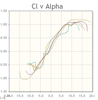
You don't have to post the manual at me. I've read them dozens since the module was first released and experienced every public flight model change over that time. What is your assertion? There are three (to keep it simple) variables here: A. UUA-1 B. freestream "F2" AOA C. Cy. All the charts in the world showing BC relationship tells nothing about AB relationship. The only factoid I can think of is that takeoff pitch of 5° gives some 11-13 UUA-1. Which relationship AB BC or AC do think is wrong. I definitely think something isn't right since AB is Mach independent in DCS but I want you to draw those graphs how you think this airplane is so we can evaluate them.
-
Have Donut? MiG-21US PFOI? Which diagram number? "Wing rock" is not a stall condition. That's controllability or stability.
-
Eh? That's Tsagi S-12 alpha sweep. UUA-1 indication is according to this formula in DCS: (Y = 1.96X + 1.41) It's not "double". I agree that this is almost certainly a weak simulation of the actual instrument. The relationship between UUA-1 indication and free stream AOA is certainly not this simple linear equation at all Mach. However, put a Post-It over the gauge and check the airplane performance for reasonableness. It looks much better in these cases.

-
"Stall" means maximum CL. That's the definition. It is independent of controllability or instrument value. The argument put forth was that the freestream AOA and the UUA-1 indication should be or more closely be 1:1 i.e. 16 freestream AOA = 16 on the gauge. Clearly in the landing regime that's impossible because the flight manual describes UUA-11 readings of 15 or so. The idea of 1:1 degrees:degrees is interesting but I haven't seen any evidence for that. The other notion is that a stall landing would be at essentially 28-32° body angle which can't be true either. Back in the day the AI flew "UUA-1" AOA according to the F2 value and it was silly. They were at double-triple-quadruple body angle in level cruise compared to pilot. Notice that the flight manual says that indication can depend if on 24V battery or 28V ground/engine power by about that ratio. At 360 km/h approach speed (0.3M), Cy max is about 1.2 assuming it can even be reached. What CL is needed for approach path? Assuming 73.5kN of lift, 360km/h 23m2, 1.225kg/m3 it's about 0.52. Assuming (again) the UUA lines are linear spacing I would put the UUA-1 reading at 18°. Is that what we get?