zippoa
-
Posts
184 -
Joined
-
Last visited
Content Type
Profiles
Forums
Events
Everything posted by zippoa
-
Aaand +1
-
What LCD you used?
-
You may try to post this message about missing knobs in their subforum, developers may add binding with some patch https://forums.eagle.ru/forum/601-jf-17-thunder/
-
Lol, they now just disappear if you launch them. Try tutorial of JF-17 and antiship missions.
-
 Looks like it's fixed. Just checked in Editor. Now each ground unit has property "Visible on display". Great!
 -
About MFCD, maybe you'll be interested. I've done panel. More info at
-
How you doin' with this issue?
-
Well, you do not need special version. PCB and video are completely independent. PCB has buttons and usb connectors, so it can be used as Thrustmaster MFD
-
Well, you may use link I posted above, it has PCB files ready for order at JLCPCB. Or you mean something other?
-
Transferring MFD panels out onto small monitors! How???
zippoa replied to subseauk's topic in Home Cockpits
Another article with description https://flyandwire.com/2018/11/08/exporting-avionics-to-secondary-monitor/ -
Transferring MFD panels out onto small monitors! How???
zippoa replied to subseauk's topic in Home Cockpits
Here is answer how to export RWR on Gazzele. Same way you can export other displays, like monitors in AJS-37 -
https://www.aliexpress.com/item/32918071718.html
-
Would recommend you to use SMD version. Bought mine here: https://www.aliexpress.com/item/32947533283.html
-
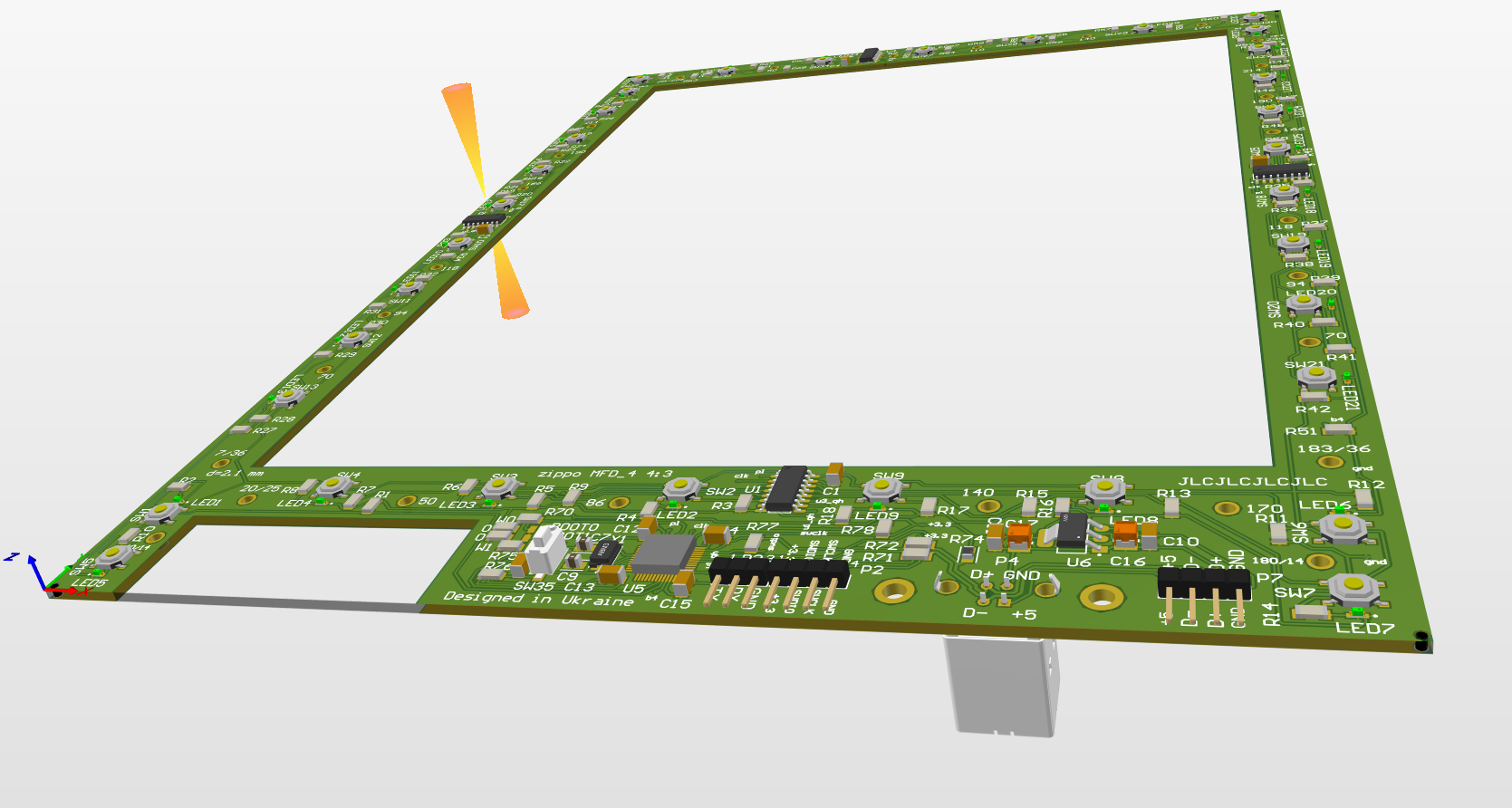
I uploaded new branch https://github.com/godor2008/MFD_3/tree/small_buttons I used there low profile tactile buttons that are in JLCPCB parts library, so they solder it instead of me. It allows to do much thinner case. Also board has cutout on left side. I made it for USB adapter board, all again to make case thinner. Here is picture for what cutout is needed:

-
I see, size of one PCB is 263 mm * 190 mm. So 190x3 = 570 mm, probably 27" monitor will fit for 3 panels
-
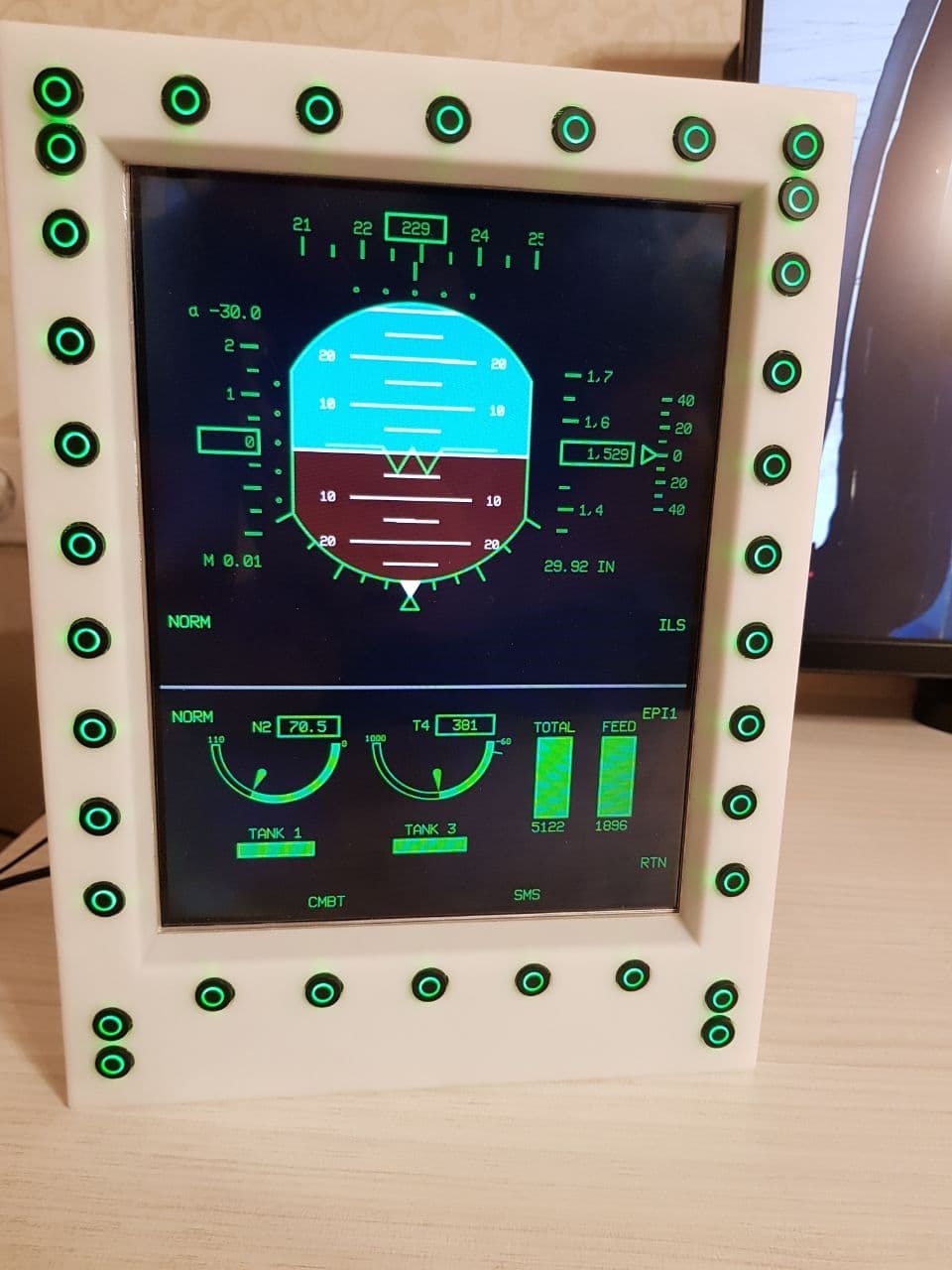
Don't know about real life. I saw some messages about using 12 inch display in real. I use 9.7 (1024*768) inch display. Size of case is 280x205 mm
-
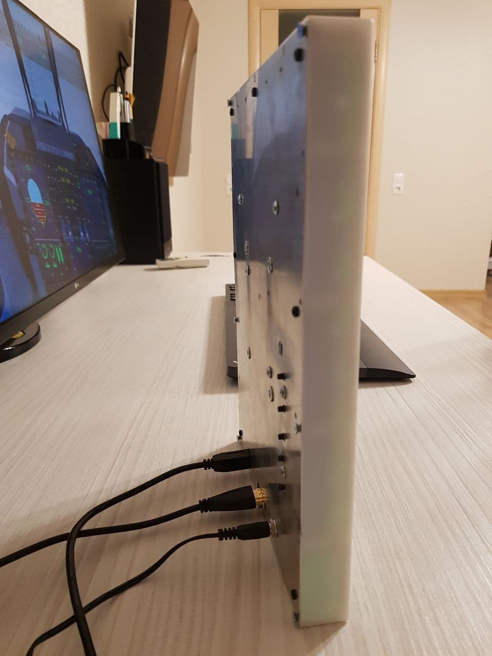
Not yet. I am thinking about small improvements, like changing to regular tactile buttons and separate LEDs. These would be SMT placed by JLCPCB. But not sure if I'll do it, since I my needs are already covered with 5 PCBs done In my custom made case, first prototype looks like this
-
Put MFDs on right bottom in your Windows monitor setup. It should fix all. And change X/Y accordingly
-
Some progress on first prototype
-
Looks amazing! How did you manufacture key caps? They look perfect. I am doing now MFD for JF-17 but using standard round keycaps, because making custom caps seems quite complicated.
-
Just saw your message :) About 84$ (45$ boards, 39$ shipping by DHL) for 5 boards. So about 17$ for 1 assembled PCB. You have to add only buttons and solder them. Buttons 100 pcs 39$ https://www.aliexpress.com/item/32947533283.html Cool black KeyCaps 100 pcs 16$ https://www.aliexpress.com/item/32918071718.html Each board has 34 button. So 1 board with buttons and keycaps will cost about 17 + 13.26 + 5.44 = 35.7 $ Case is not included, I am yet developing it
-
Making DDI's on other monitors brighter (outputted via lua file).
zippoa replied to 72hundred's topic in Home Cockpits
Win 10 has built in tool to calibrate colors https://www.windowscentral.com/how-calibrate-your-pcs-monitor-windows-10 -
Making DDI's on other monitors brighter (outputted via lua file).
zippoa replied to 72hundred's topic in Home Cockpits
I increased gamma settings in NVIDIA panel for this monitor where I export DDI. -
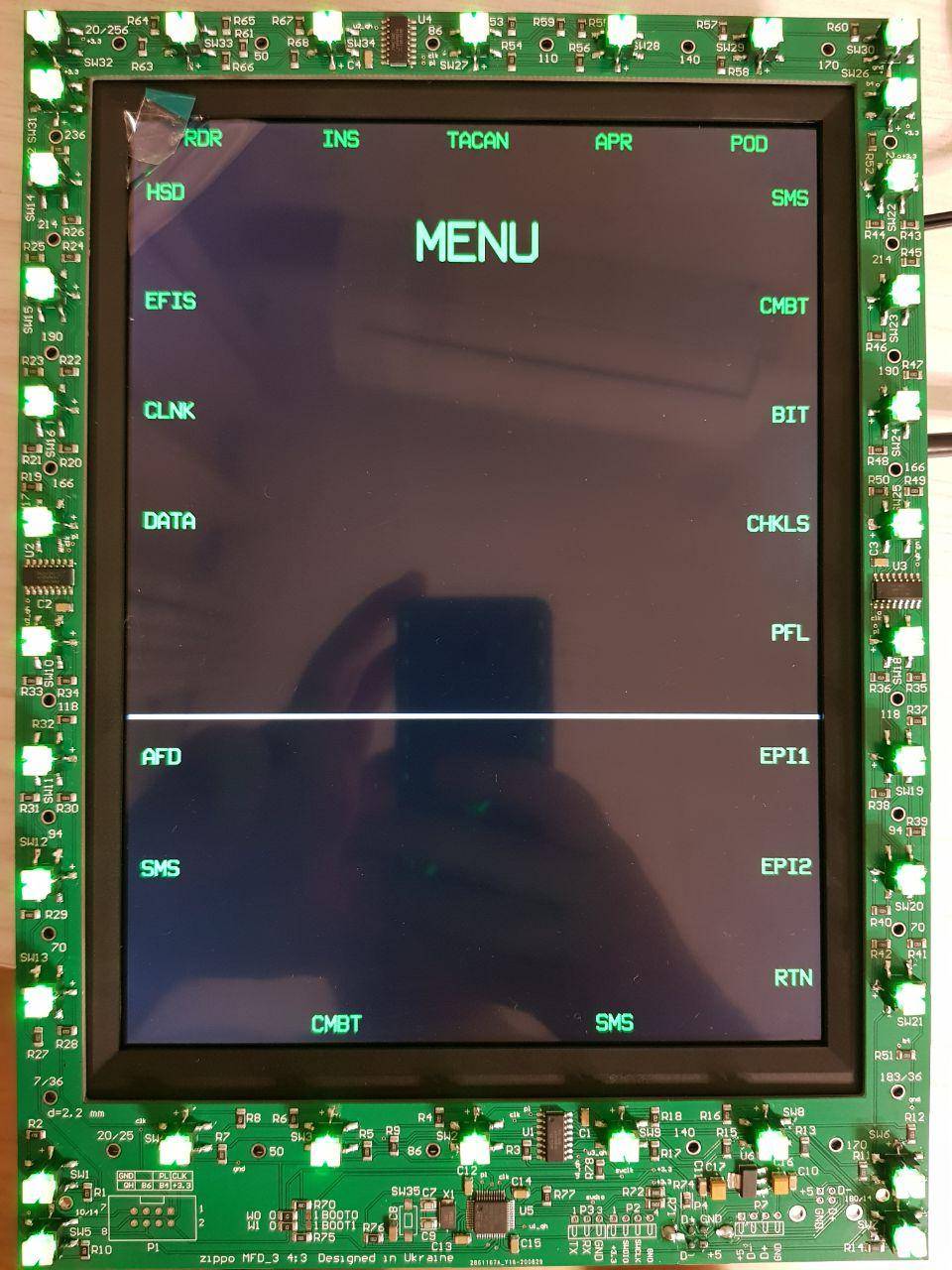
Opened github with board information and all files required for production https://github.com/godor2008/MFD_3
-
Opened github with board info and complete files for production https://github.com/godor2008/MFD_3