
Akiazusa
-
Posts
291 -
Joined
-
Last visited
Content Type
Profiles
Forums
Events
Everything posted by Akiazusa
-
I don't think there is any effect on su27,but on su25t if u start moving before 3 mins,ur heading tape reading on the HUD will get messed up in AG mode.......
-

CCRP does not work - no green cross when trying to designate target
Akiazusa replied to warmachine79's topic in M-2000
just place Designation Diamond on the target,hit AG Designate button on the throttle,then the roll order next to diamond should appear. u follow the roll order bar until the release bar appears,then u hold the trigger. IIRC the green cross is actually ur current INS steerpoint,u will need to set up the INS waypoint and select it as steerpoint for the green cross to be displayed correctly. -
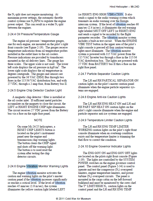
U can google TM 1-1520-Mi-17-10 (and it's also mentioned in the DCS Ka50 Manual,which has similar engines.)
-
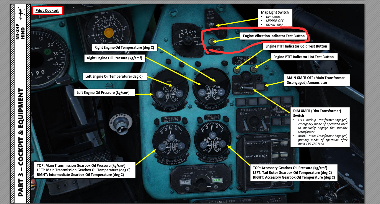
He's talking about this test button I believe,the same test button is implemented on both Mi8 and Ka50,but missing on Mi24,would be great if it's added

-
"The Engine Power Indicator is a tool to measure the equipment used to control engine power. Monitoring and control of the engines is based on the measurement of the compressor’s outlet air pressure, whose value is indicated by the two yellow markers on the vertical scale. These are then compared to the central red markers on the scale that represent different engine operating modes. The position of these mode markers is proportional to the ambient air pressure and temperature. On the central index there are three red markers: “В”, “Н”, “К”. These correspond to the compressor’s outlet air pressure at takeoff, maximum continuous, and cruise modes. To control the operation of any mode, it is necessary to compare the position of the yellow index markers with the red mode marks (В, Н, К) on the scale. Compressor outlet air pressure scale. Scaled from 5 to 10 kgf/cm2. One division equals 0.5 kgf/cm2." Those 3 bugs: o O – takeoff mode: 6min for normal (u can extend this for emergency conditions or when one engine is inoperative) o Н – maximum continuous mode: 60 min for normal o К – cruise mode:no time limit Also idle power has a 20min time limit My personal understanding of those limits are they are designed to extend the service life of the engines(material degradation or something),nothing really happens if u don't follow those time limits in DCS. (But in the sim u still can cause damage to the engine if u overheat the oil or overtorque them)
-
Hi,I noticed that the RALT reading on the steam gauge doesn't match the reading on the HUD when using English cockpit with imperial unit. It works fine when using Russian cockpit with metrics unit though. Looks like the texture for RALT steam gauge is simply based on the GAF manual,but the needle's position is calibrated with the Russian cockpit,so there is a misalignment between them. RALT steam gauge texture alignment English cockpit with Imperial unit .trk
-
- 1
-

-
How to locate ADF frequencies on the map?
Akiazusa replied to Michael-Fr's topic in DCS: MiG-29A Fulcrum
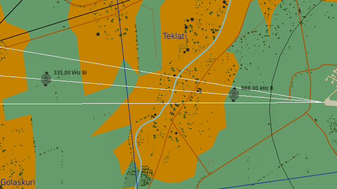
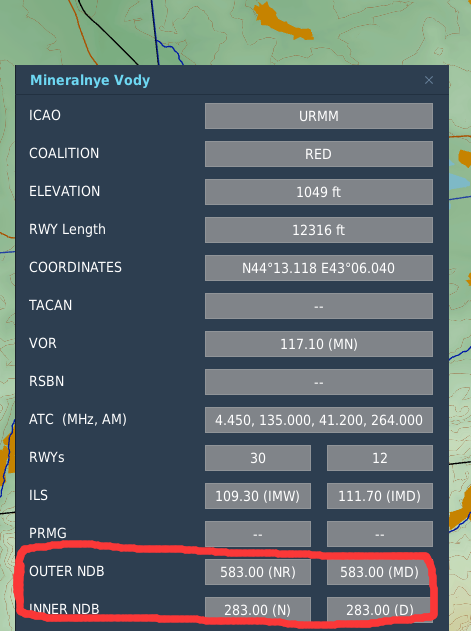
They are INNER OUTTER NDBs Also if u want to find ADF(NDB) stations away from airport,they are usually icons like this on the map(usually ended by Khz) VOR works if ur equipment support ADF in VOR bandwidth (108.0 MHz to 117.95 MHz)(I'm not a 29 pro so not sure about this for Mig29,afaik only few aircraft in DCS have raidos support this....)
-
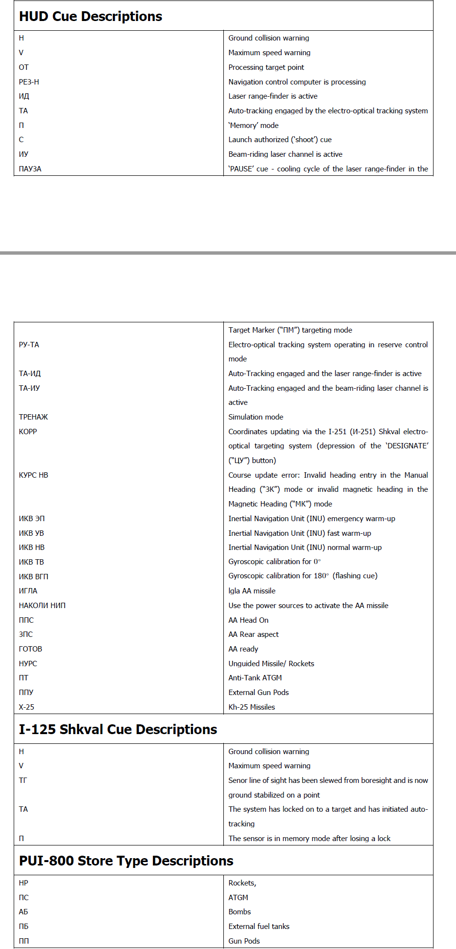
No u don't need that switch below HSI in STDBY to fire 9A4172 AT9 Vikhr missile, keep it in the right MANUAL positIon. The Left STDBY positon will set leaser to high energy target designation mode,(for laser guided weapons similar to GBUs,Hellfires,and will potentially burn the laser faster ),and for Ka50 the Only weapon uses this mode is KH25 missile(the big white missile). 9A4172 AT9 Vikhr missile is a Laser Beam Riding missile,completely different from GBUs or laser Hellfires, so u keep it in right Manual position for Vikhr. The label for this switch is really confusing,just remember,left guard open= Kh25,right guard close= everything else. Setting avionic language in the gameplay to english as for now only changes ABRIS and EKRAN language. English HUD is not ready yet for BS3,hopefully we will have it soon...(also there is a English HUD mod on the fourm,not sure if it works for the current version though.) Here is a short list for things could be displayed on the HUD and their meanings...
-
As the above post says,it's laser in PAUSE mode. If u switch the laser mode to Target Maker mode (using the switch covered by a guard below the HSI) ,then everytime u fire laser it forces to PAUSE mode for cooling,so u won't burn out ur leaser too easily. by the way that switch is default to range finder mode,and the default mode is pretty much the mode for every weapons including Vikhr ATGM,u only switch that to Target Marker mode if u want to use the KH25 missile(that big white one)
-
IIRC the MAX AOA sound is pretty much ur stall warning(but usually with FBW limiting ur control input,u won't stall like brick) there is no audio altitude warning for ground proximity,only an arrow pointing up on the HUD when ur radar altimeter is below a set radar altitude. but there is an audio warning for altitude alert,which plays the autopilot disconnect sound when u are descending passing a set baro altitude(which is set using the rollers below ap panel and is also used for autopilot altitude hold)
-
Wrong vessel spawn in Stock KA-50 BS3 Courier Mission
Akiazusa replied to Polonsky's topic in Bugs and Problems
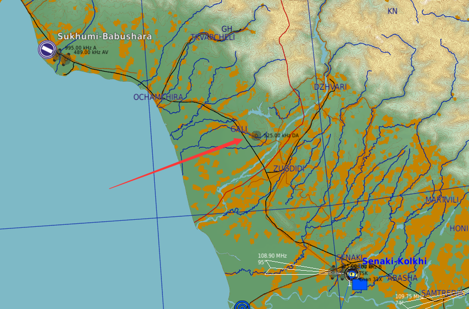
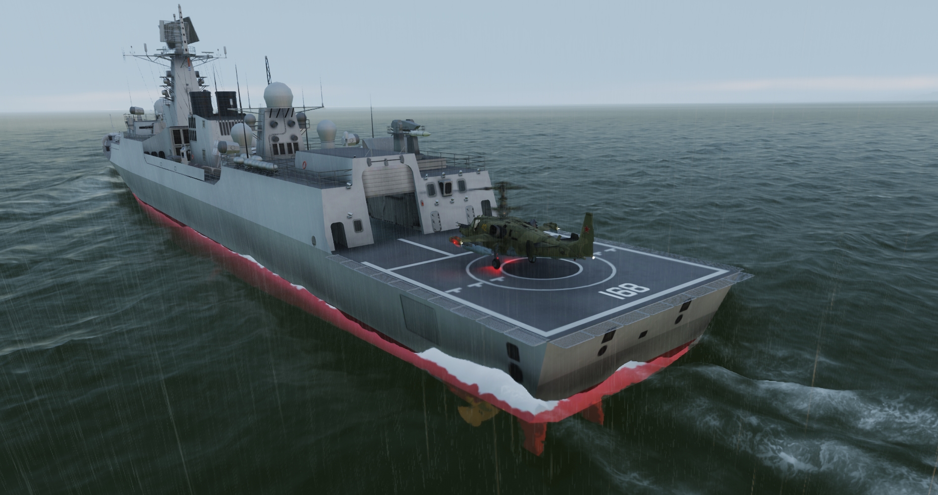
I just tried this mission,and looks like their is a small fleet in that area(In my run I saw at least 4 ships in the area,and ships in that fleet are in loose formation,every ships are like a few km away),with fog in that mission it's easy to miss the right ship........I almost missed it,when the "we got visual of u" message from frigate was triggered,I was flying passing a missile boat......but after circling around a bit more I eventually found the correct frigate with helipad... are u sure u didn't miss the right ship in the bad weather?
- 1 reply
-
- 2
-
-
I don't think changing unit to Imperial is too unrealistic for mig29 as everything is the IRL GAF mig-29 manual is in Imperial unit. I don't remember any other aircraft in DCS has this feature since it's a new feature for dcs. u can change unit from Metric to Imperial in L39 if u set avionics language setting to English Some aircraft have limited ability to change unit,like A-10C using IFFCC manual u can change distant unit to Metric to better coordinate with army I guss,but everything else is still in Imperial regardless the setting. ka50 u can switch everything on ABRIS(which is like a more advanced NS430) to different unit,but unit for steam gauges and HUD will keep in Metric. Also IIRC for FC3 version of Mig29, Mig29A and S are using Metric but Mig29G is using Imperial,but u have to switch aircraft to get that unit change. (JF has a English cockpits since it's designed for export)
-
Ka-50 III - ADF Plate channels and names
Akiazusa replied to Foxtrot1960's topic in DCS: Ka-50 Black Shark 3
if u want to change the plate to Russian but keep the cockpit in English,commenting out line 4 of the ARK_MAIN_page.lua doesn't work for me,but u can delete "TransliterateToLatDefault() " in line 150 and 163 of ARK_MAIN_page.lua ie :change UTF8_substring(TransliterateToLatDefault(ark_channel_data.name), 0, 15) UTF8_substring(TransliterateMorzeToLatDefault(ark_channel_data.callsign), 0, 6) to UTF8_substring(ark_channel_data.name, 0, 15) UTF8_substring(ark_channel_data.callsign, 0, 6) also the number behind it looks like name/callsign letter length limit(0,15 =max 15;0,6=max 6 letters) there are also some other lines but using LOCALIZE("")in that file,like the title of for the ADF plate,u can do the same to them if u want. like line 21, txt_main_caption.value = LOCALIZE("КАНАЛЫ АРК") >>editing>> txt_main_caption.value = "КАНАЛЫ АРК" -
Ka-50 III - ADF Plate channels and names
Akiazusa replied to Foxtrot1960's topic in DCS: Ka-50 Black Shark 3
weird,the font size looks okay in my game,I also tried using ur edited lua,and it also looks okay
-
IFA mode in stock Task for Challenger 1989 Campaign doesn't work?
Akiazusa replied to Polonsky's topic in DCS: F/A-18C
iirc,u switch to IFA only if there is gps available so the GPS can keep updating ur INS position,since ur mission is in 1989,so no gps in ur mission,u need to keep it in NAV after alignment. But if it initialized as IFA mode for hot/inflight start by default in non-gps era I think that's a bit odd. -
Buddy-lasing for another type from ka50 probably won't work, since it's been changed and nobody knows the code(or if it's even a NATO PRF code anymore),I guess buddy-lasing now works only between ka50s. But for now 1113 still works for su25t. If u want an answer from dev about ka50,maybe u can try Ru ka50 sub-forum using a translator,looks like people who actually did the coding sometimes answer questions their.
-
It has been changed ,1113 won't work anymore.
-
Ka-50 III - ADF Plate channels and names
Akiazusa replied to Foxtrot1960's topic in DCS: Ka-50 Black Shark 3
yes,create one if there is no one mission.miz(actually a zip)\Mods\aircraft(no "s")\Ka-50_3\Cockpit\Scripts\ARK\ARK.lua waiting for ur good news. -
Ka-50 III - ADF Plate channels and names
Akiazusa replied to Foxtrot1960's topic in DCS: Ka-50 Black Shark 3
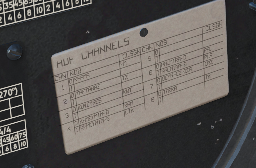
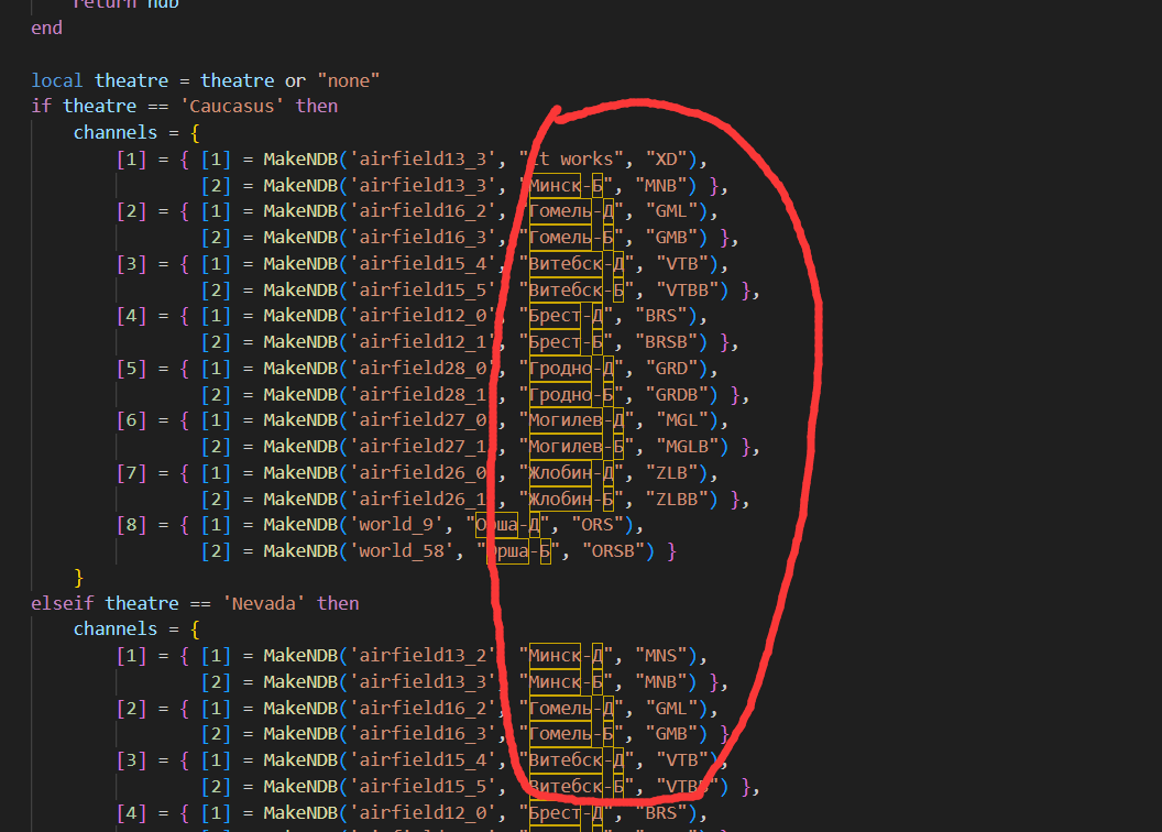
Sochi doesn't work for me either,odd...but for some airport it works,(I tried NDB in Maykop-Khanskaya) But if u don't mind modding the game file a bit,I find a way to make the plate displaying things u manually entered. First u need to delete line 152 and line 166 from ARK_MAIN_page.lua,but this file seems can't be packed into the .miz file,so modding the game file is needed. (those 2 controllers seems keeps overriding what u entered from ark.lua using their own logic.) And here is my ARK.lua,u can pack it into the .miz file without touching the original game file. ARK.lua in my ark.lua,u could change the name and callsign(in red circle) to what ever u what and the plate in cockpit will display them. for the beacon_id:(airfilexx_xx or world_xx),u can ignore them,I haven't figure out how to use them yet,and they don't seems affect anything for now To edit ADF frequencies,use mission editor,change them to whatever u want(but no automatic update for the the ADF plate after modding),then u can manually change beacon "name" and "callsign" in my ark.lua to match them(or anything u want to be displayed on the plate) .(also u can try adding more functions to it,or merging those theatres into one section) For Syria,I guess it's not called "syria" for lua variable,as "elseif theatre == 'Syria' then" doesn't work for it,but when I change that to "else",things start working.
-
Ka-50 III - ADF Plate channels and names
Akiazusa replied to Foxtrot1960's topic in DCS: Ka-50 Black Shark 3
On Caucasus and Nevada map looks like if that as long as the NDB is in Beacon.lua,all u have to do is to change the ARK settings in ME to match the frequency in Beacon.lua and the plate will be automatic updated to match their names and callsigns. I tried messing with ark.lua to make it works the same way for Syria but sadly no luck either...............I will try more tomorrow........................ maybe using a kneeboard is easier. -
check procedures Engine Test Regulator buttons won't work
Akiazusa replied to Antiguedad's topic in Bugs and Problems
In my memory it's modeled. I think the test button only lower the "protection kicks in" threshold a bit, u still need a relative high power to get that light on(like .in normal operation the light comes on at 100% red line temp,but with test button pushed it comes on at 80% red line temp) I can't find test procedure of it for mi-8 in any manual. But here is the procedure for ka50,which uses a similar engine,I remember on mi-8 it's similar. -
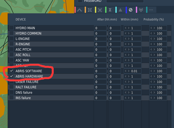
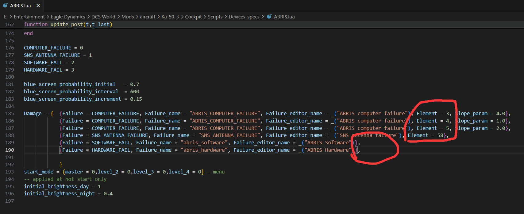
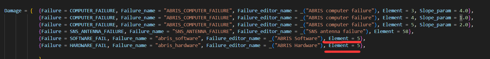
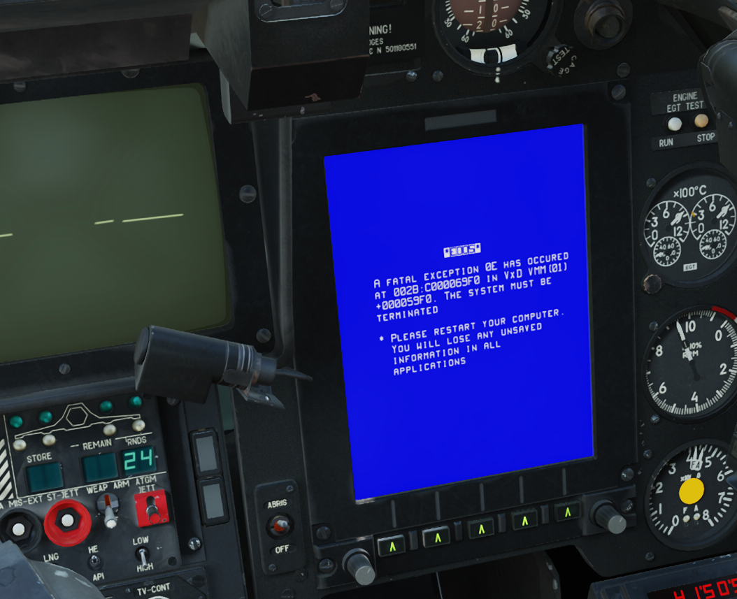
Hi. This is a hidden one,trivial thing,nothing really hurt. also I think I find the potential cause of it. There are lots of failures you can set for ka50 using mission editor. But those 2 failures:ABRIS SOFTWARE/ABRIS HARDWARE,seems broken. If u set them in ME,then it won't trigger the failure in game. track.....(I set ABRIS software failure in ME,within 1 min,100% probability,but I guess in the track nothing really happened,the failure is not even displayed in the after mission report) mission editor ABRIS failure settings .trk I checked \DCS World\Mods\aircraft\Ka-50_3\Cockpit\Scripts\Devices_specs\ABRIS.lua and other lua files. Looks like every other failure has an "element" assigned to it,but only those 2 don't have them. I tried adding "elements" to them and things suddenly start working. after adding "elements",abris software failure triggers a blue screen,also hardware failure works too. It works okay in old dcs world version without "element",but I guess some updated new core system changed it,looks like now an "element" is always required? I don't know what exact those element are,(maybe linked to DM? I don't want get a blue screen every time when hit by7.62 bullets) ,so better let the team know and find a suitable fix.(when free of course) Thanks in advance. (sorry for reporting so many things,I guess I'm addicted to this heli recently...fly it a looooot. nice sim product) mission editor ABRIS failure settings .trk
-
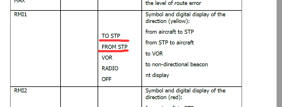
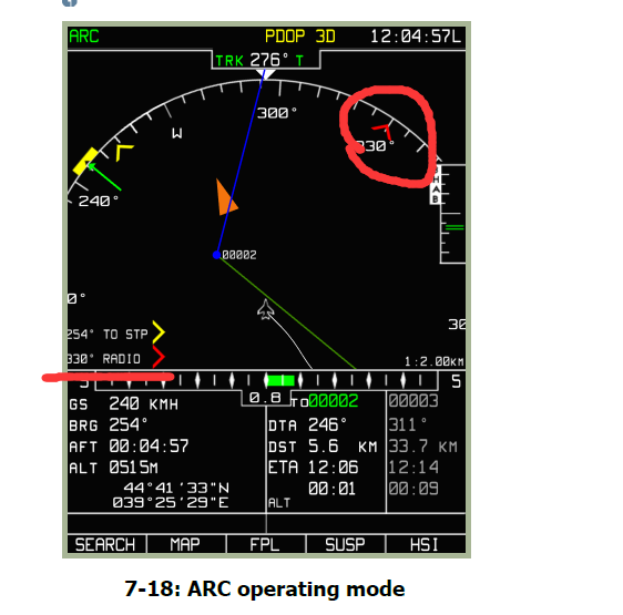
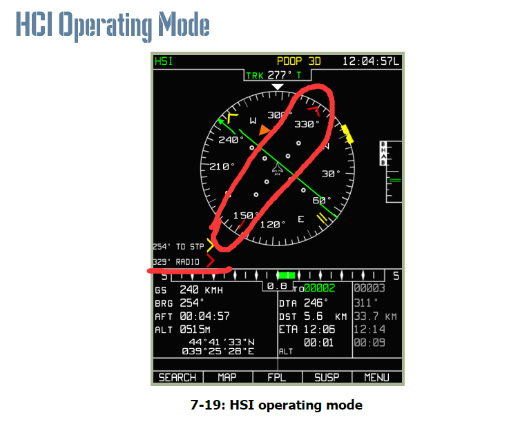
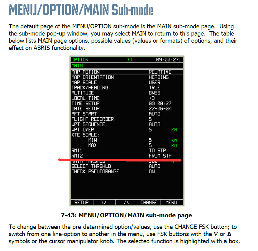
Hi...another small bug,minor detail. ABRIS RMI2 pointer (Red pointer on ACR and HSI page)can show "TO STP" "FROM STP" and "RADIO" information depending on setting. It's default to "RADIO" which shows information from AKR-22 ADF When no ADF signal is received,it will not showing up of course. It works fine if u change the setting with ADF signal being received. Also if u are already in "TO STP' or "FROM STP" mode,and then the ADF signal is gone,the RIM2 pointer will continue working fine. But if u change it's setting from "RADIO" to "TO STP' or "FROM STP" when no ADF signal is received,the RIM2 pointer will not show up,until u have ADF signal being received and got the setting cycled back through "RADIO". RIM2 not showing up.trk Just a minor detail,hope for a fix when free,thanks.
-
bump Distance to go to STP.trk
-
Question on Chuck's guide controller setup
Akiazusa replied to vampyrgtr's topic in DCS: Ka-50 Black Shark 3
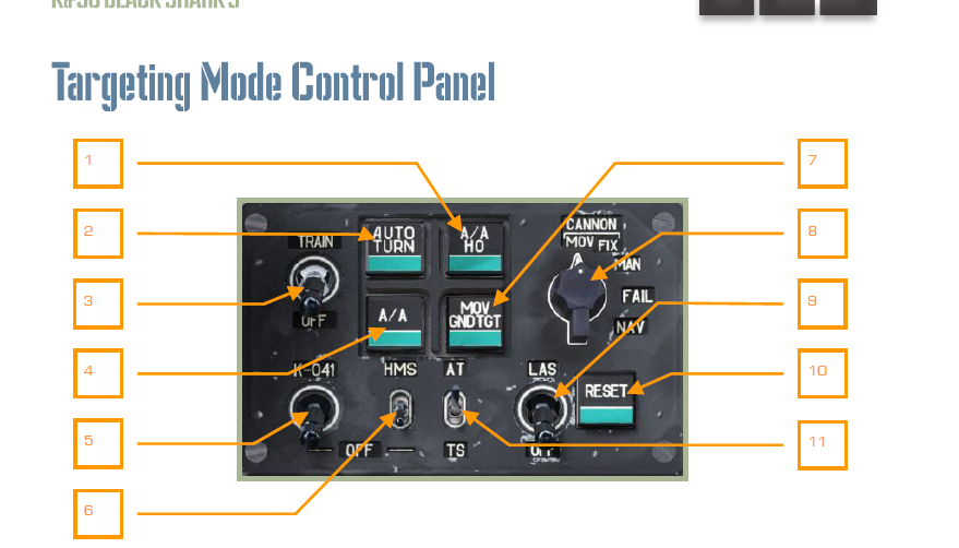
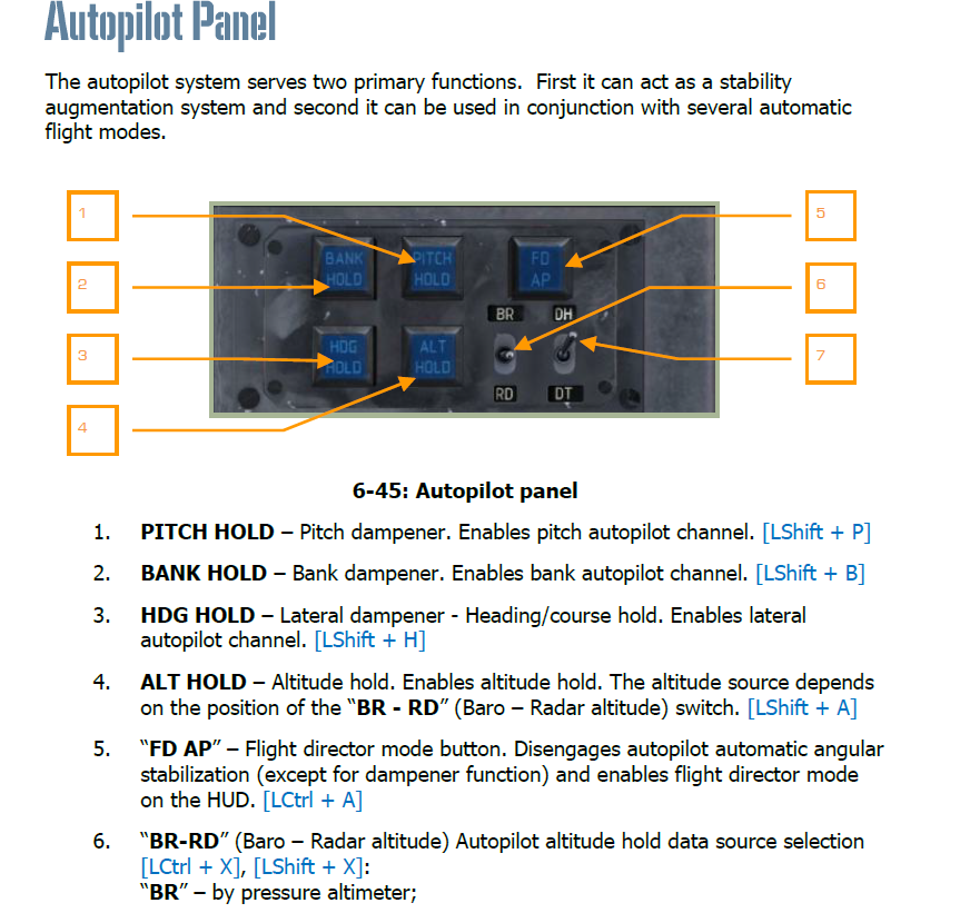
Looks like it's 95% mapped with buttons/switches on the real Ka50 stick/collective. The only thing missing is which is a switch on the collective,pretty useful if u want to descend rapidly.(evade radar missile) I guess there aren't many switches on the real ka50's stick/collective to fill up the Warthog HOTAS. I personally uses these panels/switches(which are not on the real ka50 hotas) quite often when flying/combat. also these 2 panels: (especially the 4 blue buttons on the left,also FD button will change the autopilot mode from holding to damping, pretty useful for hand flying,also u can just hold trim button for that,will do the same) (mainly the 5 green buttons,(the reset one is already mentioned in Chuck's guide),and the laser arm switch(u can't always leave it to on,since the laser on ka50 is quite easy to burnt out) ) u could bind the remaining controls to them if u like.