All Activity
- Past hour
-

fixed internally AGM -154C's not hitting their target
BIGNEWY replied to boo_n_817's topic in Weapon Bugs
Hi, this is fixed internally and will be in a future patch once QA checks are completed, thank you -
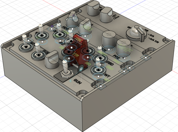
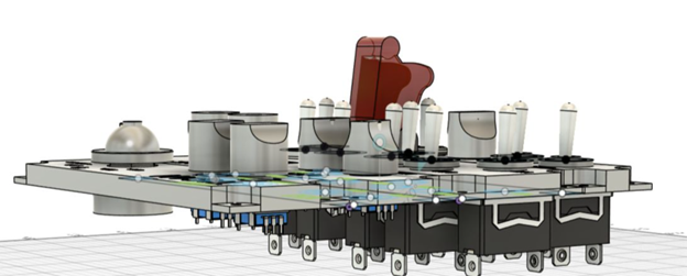
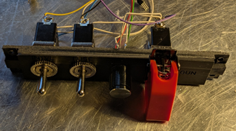
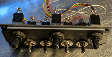
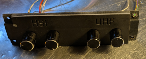
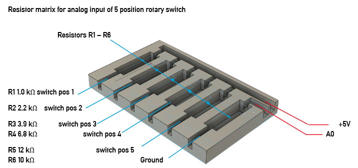
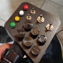
I loooove flying the Northrop F-5E in DCS. As I am purely in VR, input of controls with my mouse is often too slow and clumsy. While using the MOZA MTP throttle and MTLP panel with a Rhino FFB base and WinWing ViperAce stick I found that I still lack certain controls to enjoy flying and fighting in the F-5. Looking around I found nothing really satisfying to solve my problem. Finally, I decided to find a solution on my own. The plan: Build a button box for · TACAN modes, tens, ones, X/Y · UHF modes, presets · HSI input HDG & CRS · Stations select 7 stations · Interval setting 3 positions · Bomb fuse 3 positions · Weapon mode selector · GUN on and off My take on this was to use · TACAN: one 5-position selector, two rotary encoder · UHF: two rotary encoders · HSI: two rotary encoders · Stations: seven ON/OFF rocker switches · Interval: one ON/OFF/ON rocker switch · Fuse: one ON/OFF/ON rocker switch · WP mode one rotary encoder · GUN: one ON/OFF rocker switch Two Arduino Leonardo controllers to emulate two USB game controllers for Windows. Overall split across 2x Arduino Leonardo So that all inputs fit comfortably on the pins (and you avoid serial conflicts), I choose this distribution: Leonardo A (Hardy’s F-5E ButtonBox A): 5 rotary encoders with pushbutton 5×(A/B) = 10 lines + 5×Push = 5 lines ⇒ 15 pins. 1× 5-position selector switch, 1 analog pin (via resistor network) Leonardo B (Hardy’s F-5E ButtonBox B): 2 rotary encoders with push, 6 pins 8× ON-OFF rocker, 8 pins 2× ON-OFF-ON rocker, 4 pins The Box The box needed to be printed on my Anycubic Kobra 2PRO and Photon Mono 2. So, I drafted the Box and panels with fusion, to export stl files and slice them. My filament printer caused some heat deformation of the box and the base plate. Therefore, I had to split the large bodies to obtain separate STL files for four bodies of the base plate and two bodies of the box. The plates were also split, with the lower part printed using the FDM process and the upper part printed using the resin process for better resolution. The parts were glued together. Panel one: bomb interval, fuse setting, external stores rotary switch, gun/cam switch with cover Panel two: armament position selector switches Panel three: HSI heading and CRS, AN/ARC-164 UHF mode and frequency mode Panel four: TACAN tens, ones, X/Y, modes Wiring General wiring diagram (for all buttons/switches) One side of each switch to GND, the other side to an input with INPUT_PULLUP. Logic: LOW = active, HIGH = inactive. Also connected encoder A/B to GND (A and B each to inputs with INPUT_PULLUP), common ground of the encoder to GND. Ground routing: one clean star ground (GND bus) per board. No need to ground the two boards together - both have a common ground via USB anyway. 5-position selector switch as analog value. Instead of 5 individual inputs, I used a single analog pin with resistors: Connect the analog pin with a 10 kΩ pull-down to GND. The common contact of the 5-position switch goes to +5 V via one position resistor each to analog pin. Resistors (R→+5 V): 1 kΩ, 2.2 kΩ, 3.9 kΩ, 6.8 kΩ, 12 kΩ. Each position contact then supplies a unique voltage at A0 (the sketch assigns the ADC values to 5 “bands”). Pinout & Button Mapping Arduino Leonardo A Encoders 1-5 Encoder Pin A Pin B Push Button Enc1 D2 D3 D4 1 (+), 2 (−), 3 (Push) Enc2 D5 D6 D7 4 (+), 5 (−), 6 (Push) Enc3 D8 D9 D10 7 (+), 8 (−), 9 (Push) Enc4 D11 D12 D13 10 (+), 11 (−), 12 (Push) Enc5 A2 A3 A1 13 (+), 14 (−), 15 (Push) 5-position Analog Selector Function Pin Button 5-position analog selector A0 (resistor ladder, 10k pulldown) 19–23 (one held active) Notes: Button numbers are 1-based (human-friendly); HID reports them 0-based internally. Buttons 16–18 are intentionally left unused (reserved block). Encoders use Timer1 @1 kHz, LatchMode=FOUR3, with non-blocking pulse queue (~25 ms pulses). Selector uses resistor ladder on A0; adjust bands in firmware if resistor tolerances differ. Arduino Leonardo B Encoder 6-7 Encoder Pin A Pin B Push Button Enc6 D2 D3 D4 1 (+), 2 (−), 3 (Push) Enc7 D5 D6 D7 4 (+), 5 (−), 6 (Push) ON–OFF Rockers Pin Button (Up) Button (Down) D0 26 25 D1 24 23 D8 22 21 D9 20 19 D10 18 17 D11 16 15 D12 14 13 D13 12 11 3-position Rockers Rocker Up Pin Down Pin Button (Up/Down/Mid) A A1 A2 27 / 28 / 29 B A3 A4 30 / 31 / 32 +5V from board to top of resistor R1-R5. R1-R5 output to 5 position rotary switch ports 1-5 Common port of rotary switch to board A0 R6 from board GND (ground) to A0 Clear voltages at A0 (at 5.00 V supply & 10 kΩ pull-down) Position Ri VA0 (V) ADC raw value (≈0–1023) 1 1 kΩ 4.55 V ≈ 930 2 2.2 kΩ 4.10 V ≈ 839 3 3.9 kΩ 3.60 V ≈ 736 4 6.8 kΩ 2.98 V ≈ 609 5 12 kΩ 2.27 V ≈ 465 (Tolerances of resistors and 5 V rail cause slight deviations – that's why we use bands around these target values in the sketch.) Wiring in words (position assignment) · Pos. 1 pad → 1 kΩ → +5 V · Pos. 2 pad → 2.2 kΩ → +5 V · Pos. 3 pad → 3.9 kΩ → +5 V · Pos. 4 pad → 6.8 kΩ → +5 V · Pos. 5 pad → 12 kΩ → +5 V · COM/wiper →A0 · A0 → 10 kΩ GND Tip for testing: Set the rotary switch to one position, hold the multimeter on A0 against GND – the table (voltage) above should be roughly correct. If your measurements are slightly off, extend/shift the posBands[] in the sketch accordingly. Software: Libraries · Rotary Encoder: RotaryEncoder by Matthias Hertel (polling based, works on any pins). · HID Joystick: Joystick by Matthew Heironimus (Leonardo/Micro friendly). HID strategy (what the sim sees) · Treat each encoder as two momentary buttons: o CW step → press & release “Button X+” o CCW step → press & release “Button X−” · Encoder pushes and rockers map to normal buttons. · ON-OFF-ON uses three buttons (UP MIDDLE DOWN). · ON-OFF uses 2 buttons (UP DOWN) · 5-pos → 1 analog axis with 5 bands (with resistor ladder). If anybody is interested I will be able to provide .stl files for filament and resin print, a bill of material with sample merchants delivering them and the sketch files for both Arduinos, just drop me a line. Hope this will either find some builders using my plan or inspires to create their own box.null

-
reported Navigation Alignment after repair
BIGNEWY replied to KnuckleDaWae's topic in Bugs and Problems
Hi all, I have marked the thread reported, this seems to be related to the battery state, thank you for the track replays and your insight to the issue, it has helped us. -
Using Desktop View might be the current solution while the headset is on.
-
Wrong, it can be placed into faults section in ME. For those who wish to face the true challenge. Failures can be simulated in DCS, but I am not sure about degradation. E.g. change the radar range.
-
 yqy7320 joined the community
 -
Первый пост откорректирован в связи с продажей некоторых позиций.
-
Hi, requesting an automated ATC system for approach, departure, ground and carrier operations, instead of constantly needing to use the F10 Menu ATC. Kind regards, RWC
-

EA-18G Style Electronic Warfare Script
toan replied to __Timberwolf__'s topic in Scripting Tips, Tricks & Issues
Hi, I'm trying to use this amazing script, and loaded the Demo mission OK, replacing the default F/A 18-C by the CJS Growler, as a client named 'Growler'. The mission launches correctly and everything seems fine, including the message 'jamming submenus created', unfortunately I can never invoke the jamming dialog . Do I correctly invoke the F10 menu by the usual '\' key ? Or do I need to wait for some delay for the EW jammer to spool up ? Last, do I have to be the pilot of one of the strike F-15 (which I don't own... and that never appear on the map...) ? Thanks for your help. -
The control mode for man-in-the-loop weapons can be changed in the JF17's dedicated settings. Simply set it to designated. However, the issue of the ground not being displayed at long ranges will need to be resolved by ED.
-
That require ED implement them first.
-
Maybe we should have a checkbox, then. A brand new (or at least properly maintained) Soviet MiG-29 would have the radar working OK with the SPO-15, but for most of the jet's lifetime, it seems that it was a common problem which was very often left unfixed. That said, if we're being consistent, this should just work. DCS doesn't simulate bad maintenance, deterioration due to conditions (big issue for F-4 and its missiles in Vietnam) and other such concerns that often determine real world performance much more than factory E-M diagrams do.
-
DCS MiG-29A Flight performance and air drag seems weird
BIGNEWY replied to HoMeBoY's topic in DCS: MiG-29A Fulcrum
Hi, please include a track replay on Caucasus showing the issue and we can review it. If you have any public evidence to support your claims please dm me, but comparing to other modules isnt probably a good idea, each aircraft has its quirks and characteristics. thank you- 1 reply
-
- 1
-

-
Premise, I fly almost all DCS modules and I have 5+ years in the sim to what I consider a professional level. I am also a student pilot. I understand the flight model is the same as FC and it was considered more than good and realistic already, but right now the MiG-29A behaves completely different from any other module. For example: - it's very difficult to bleed air speed, even when idle and pitching up. And it seems it never really stalls and not even buffet. I could fly at around 120kts easily but it seems a very low speed to me - because of the difficulty of bleeding air speed, landings are weird and generally flat and it float forever - you can flare on land and then keep the nose up almost forever - you can sustain AB climb, sometimes supersonic, way past 35,000ft - the jet overall seems faster and agile of anything else out ther in DCS. I don't know how a MiG29 is in real life and to be honest I would expect this kind of performance from a modern military jet, but then all the others modules like F/A-18 and F-16 must be wrong then as they have less performance than the MiG29. In general I find F-16, F-14 and F-4 (in general Heatblur modules) to be the best transmitting realistic reactions and performances when it comes to modern jets....so TLDR, this MiG29A left me perplexed as it feels very arcade to me
-
THX! Oh dear, it's getting more and more fun in DCS.
-
Did they? Admiral Helsey, who was ultimately responsible for the decision to press on into the storm, and not to take precautions earlier (to be fair, weather reports were contradictory), got away with no real sanctions for his 'error of judgement'. If anyone else got punished, that would seem unfair. In addition to the many damaged ships, three destroyers were sunk, 802 seamen lost, and 146 aircraft destroyed - most due to breaking loose in hangers due to extreme rolling. USS Monterey (CVL-26) suffered a fire as a result, fortunately brought under control. I suspect most DCS players think little about this aspect of warfare: extreme weather, or even just enduring cold for armies ill-equipped for it, sometimes inflicts more damage than the enemy. Not something you can simulate, or would really want to (though proper pitching decks for CVs would be nice), but a sobering thought.
-
Sorry but changing labels isn't something that is going to happen, not many people look at labels and it has no effect on the weapon in game, reporting this and assigning dev time to it would be a waste of resources. thank you
-
No problem for me
-
9.12 avionics manual, SPO-15 maintenance manual. Also SME ground technician said their pilots used SPO-15 in type-similar BVR training.
-
So it’s NOT my targeting ability at fault!
-

cannot repoduce and missing track file Ekran and voice warning without sound
tpisko replied to tpisko's topic in Bugs and Problems
Yes, same for me. After restart it is back to no sound. - Today
-
Hi, I dont think this is a bug, it is a day attack helicopter as far as I am aware, but I will check with the team. thank you
-
Wow
-
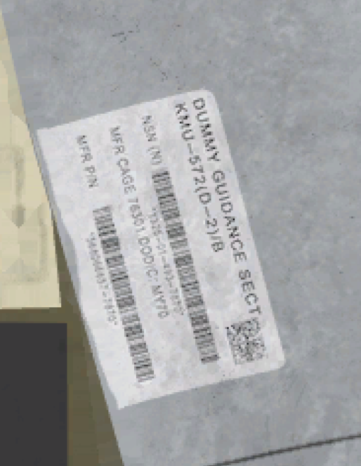
Current situation GBU-54's tail guidance kit is labeled as 'Dummy kit, KMU-572(D-2)/B' But according to congress record, KMU-572(D-2)/B is Dummy set for load training. First Material CONGRESSIONAL RECORD—SENATE April 28,2025 In this record, They mention two KMU-572s "KMU–572(D–2)/B Trainer (JDAM)," and "KMU–572 JDAM Guidance Kits for GBU–38/54;" Both are handled separately, and KMU-572(D-2) is specifically mentioned as dummy/training kit. Credit : CREC-2025-04-28-pt1-PgS2597.pdf Second Material In this image, Label is same as in game. And there is stencil "MK82 LOAD TRAINER NOT FOR FLIGHT" on other side of label. Even the wings are welded. And using common sense, Using Dummy kit on live ammo does not make sense. Third Material DVIDS - Images - Munitions Systems Specialists Assemble GBU-38 [Image 7 of 15] Label should be like this image (GBU 38 also use KMU-572B) 'Guidance kit KMU-572B' TLDR; Label on tail guidance kit of GBU 54 should be fixed. Also, add label same to GBU-38 since both are same tail guidance kit.
-

MiG-29A Fulcrum Launch | DCS Update Summary
draconus replied to Graphics's topic in Official Newsletters
The first 4th gen, because we already have full-fidelity MiGs: 21, 19 and 15. -
Manual filament swap during print.