MFG62 Joker
-
Posts
362 -
Joined
-
Last visited
-
Days Won
1
Content Type
Profiles
Forums
Events
Everything posted by MFG62 Joker
-
sure thing, you can rename Arduino Leonardo to Rapti's ButtonBox, if you like ... Needs to be done in Arduino Software and will be flashing the Arduino in question with the software sketch that you use to define your windows USB game controller.
-
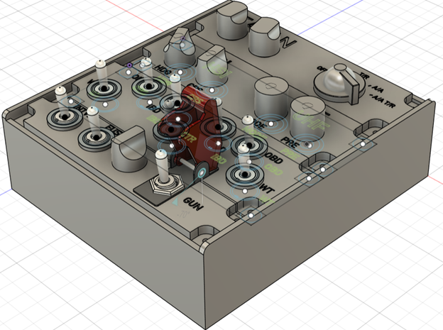
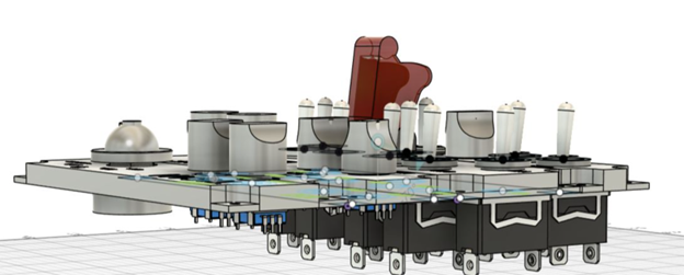
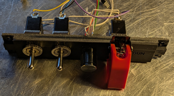
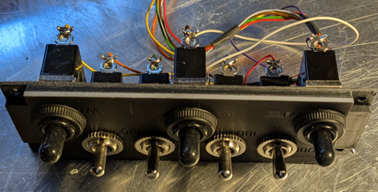
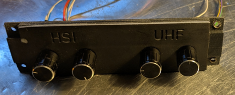
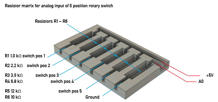
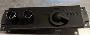
I loooove flying the Northrop F-5E in DCS. As I am purely in VR, input of controls with my mouse is often too slow and clumsy. While using the MOZA MTP throttle and MTLP panel with a Rhino FFB base and WinWing ViperAce stick I found that I still lack certain controls to enjoy flying and fighting in the F-5. Looking around I found nothing really satisfying to solve my problem. Finally, I decided to find a solution on my own. The plan: Build a button box for · TACAN modes, tens, ones, X/Y · UHF modes, presets · HSI input HDG & CRS · Stations select 7 stations · Interval setting 3 positions · Bomb fuse 3 positions · Weapon mode selector · GUN on and off My take on this was to use · TACAN: one 5-position selector, two rotary encoder · UHF: two rotary encoders · HSI: two rotary encoders · Stations: seven ON/OFF rocker switches · Interval: one ON/OFF/ON rocker switch · Fuse: one ON/OFF/ON rocker switch · WP mode one rotary encoder · GUN: one ON/OFF rocker switch Two Arduino Leonardo controllers to emulate two USB game controllers for Windows. Overall split across 2x Arduino Leonardo So that all inputs fit comfortably on the pins (and you avoid serial conflicts), I choose this distribution: Leonardo A (Hardy’s F-5E ButtonBox A): 5 rotary encoders with pushbutton 5×(A/B) = 10 lines + 5×Push = 5 lines ⇒ 15 pins. 1× 5-position selector switch, 1 analog pin (via resistor network) Leonardo B (Hardy’s F-5E ButtonBox B): 2 rotary encoders with push, 6 pins 8× ON-OFF rocker, 8 pins 2× ON-OFF-ON rocker, 4 pins The Box The box needed to be printed on my Anycubic Kobra 2PRO and Photon Mono 2. So, I drafted the Box and panels with fusion, to export stl files and slice them. My filament printer caused some heat deformation of the box and the base plate. Therefore, I had to split the large bodies to obtain separate STL files for four bodies of the base plate and two bodies of the box. The plates were also split, with the lower part printed using the FDM process and the upper part printed using the resin process for better resolution. The parts were glued together. Panel one: bomb interval, fuse setting, external stores rotary switch, gun/cam switch with cover Panel two: armament position selector switches Panel three: HSI heading and CRS, AN/ARC-164 UHF mode and frequency mode Panel four: TACAN tens, ones, X/Y, modes Wiring General wiring diagram (for all buttons/switches) One side of each switch to GND, the other side to an input with INPUT_PULLUP. Logic: LOW = active, HIGH = inactive. Also connected encoder A/B to GND (A and B each to inputs with INPUT_PULLUP), common ground of the encoder to GND. Ground routing: one clean star ground (GND bus) per board. No need to ground the two boards together - both have a common ground via USB anyway. 5-position selector switch as analog value. Instead of 5 individual inputs, I used a single analog pin with resistors: Connect the analog pin with a 10 kΩ pull-down to GND. The common contact of the 5-position switch goes to +5 V via one position resistor each to analog pin. Resistors (R→+5 V): 1 kΩ, 2.2 kΩ, 3.9 kΩ, 6.8 kΩ, 12 kΩ. Each position contact then supplies a unique voltage at A0 (the sketch assigns the ADC values to 5 “bands”). Pinout & Button Mapping Arduino Leonardo A Encoders 1-5 Encoder Pin A Pin B Push Button Enc1 D2 D3 D4 1 (+), 2 (−), 3 (Push) Enc2 D5 D6 D7 4 (+), 5 (−), 6 (Push) Enc3 D8 D9 D10 7 (+), 8 (−), 9 (Push) Enc4 D11 D12 D13 10 (+), 11 (−), 12 (Push) Enc5 A2 A3 A1 13 (+), 14 (−), 15 (Push) 5-position Analog Selector Function Pin Button 5-position analog selector A0 (resistor ladder, 10k pulldown) 19–23 (one held active) Notes: Button numbers are 1-based (human-friendly); HID reports them 0-based internally. Buttons 16–18 are intentionally left unused (reserved block). Encoders use Timer1 @1 kHz, LatchMode=FOUR3, with non-blocking pulse queue (~25 ms pulses). Selector uses resistor ladder on A0; adjust bands in firmware if resistor tolerances differ. Arduino Leonardo B Encoder 6-7 Encoder Pin A Pin B Push Button Enc6 D2 D3 D4 1 (+), 2 (−), 3 (Push) Enc7 D5 D6 D7 4 (+), 5 (−), 6 (Push) ON–OFF Rockers Pin Button (Up) Button (Down) D0 26 25 D1 24 23 D8 22 21 D9 20 19 D10 18 17 D11 16 15 D12 14 13 D13 12 11 3-position Rockers Rocker Up Pin Down Pin Button (Up/Down/Mid) A A1 A2 27 / 28 / 29 B A3 A4 30 / 31 / 32 +5V from board to top of resistor R1-R5. R1-R5 output to 5 position rotary switch ports 1-5 Common port of rotary switch to board A0 R6 from board GND (ground) to A0 Clear voltages at A0 (at 5.00 V supply & 10 kΩ pull-down) Position Ri VA0 (V) ADC raw value (≈0–1023) 1 1 kΩ 4.55 V ≈ 930 2 2.2 kΩ 4.10 V ≈ 839 3 3.9 kΩ 3.60 V ≈ 736 4 6.8 kΩ 2.98 V ≈ 609 5 12 kΩ 2.27 V ≈ 465 (Tolerances of resistors and 5 V rail cause slight deviations – that's why we use bands around these target values in the sketch.) Wiring in words (position assignment) · Pos. 1 pad → 1 kΩ → +5 V · Pos. 2 pad → 2.2 kΩ → +5 V · Pos. 3 pad → 3.9 kΩ → +5 V · Pos. 4 pad → 6.8 kΩ → +5 V · Pos. 5 pad → 12 kΩ → +5 V · COM/wiper →A0 · A0 → 10 kΩ GND Tip for testing: Set the rotary switch to one position, hold the multimeter on A0 against GND – the table (voltage) above should be roughly correct. If your measurements are slightly off, extend/shift the posBands[] in the sketch accordingly. Software: Libraries · Rotary Encoder: RotaryEncoder by Matthias Hertel (polling based, works on any pins). · HID Joystick: Joystick by Matthew Heironimus (Leonardo/Micro friendly). HID strategy (what the sim sees) · Treat each encoder as two momentary buttons: o CW step → press & release “Button X+” o CCW step → press & release “Button X−” · Encoder pushes and rockers map to normal buttons. · ON-OFF-ON uses three buttons (UP MIDDLE DOWN). · ON-OFF uses 2 buttons (UP DOWN) · 5-pos → 1 analog axis with 5 bands (with resistor ladder). If anybody is interested I will be able to provide .stl files for filament and resin print, a bill of material with sample merchants delivering them and the sketch files for both Arduinos, just drop me a line. Hope this will either find some builders using my plan or inspires to create their own box.

-
Anybody found out about the arguments for description.lua for Pilot suit? I can't seem to get it to work while trying to "invent" entries in the description.lua while using the templates for Pilot suit top and suitBottom. Also, it seems there are two different liveries in use for Pilot in cockpit and Pilot ejected. Really no fun at all to try and work yourself through this mess with important information missing.
-
Hi there, like we say in Bavaria: "ja, is denn scho Weihnochdn?" ... feels like chistmas, no?! We recenly formed the German Squad MFG 62. We are still in a forming state, with 4 Pilots aiming for combat readiness. With great pleasure I see what is planned here, it seems to be a perfect fit to our vision of gameplay we aim for. More information about us is: Welcome to our squadron's German website. https://mfg62.de/ A brief introduction: We fly aircraft from the golden era of the Cold War in DCS. Our core values are an authentic, honest and reliable personality initiative team spirit flying skills and the will to achieve good airmanship humor is when you laugh anyway, especially at yourself If you are keen to constantly improve your own knowledge and skills as well as those of the team, you can find an aeronautical home in MFG62. Our motto: boyz 'n' toyz. How it works here: The founders have formed the staff that deals with the formation, operation and further development of the squadron. The further organization is planned to be flat, not hierarchical. Roles are determined by the staff based on proven skills and operational conditions. The scope of the game: Our current flight is the DCS community mod “Douglas A4E-C Skyhawk”. Training takes place as part of the Mediterranean air fleet in Cyprus, more precisely at the RAF base Akrotiri. Consequently, the “DCS: Syria Map” is the only purchase module required. For our carrier training, the US Navy has provided us with our “mother”, “the FID” - first in Defense, “CVA-59 USS Forrestal”. Here we hope to achieve our “Carrier Qualification”. How are we doing: Our plan is to complete the airfield-based training by the fall of 2024, including weapons training. Extensive training documents and mission scenarios are in the works. Then our baptism of fire will take place on servers such as the “Enigma Cold War Server”, which is now operated by Heatblur. The primary goal is to achieve operational objectives with as few losses as possible. In the future, we plan to use additional modules such as the Northrop F-5E “Tiger II” and McDonnel Douglas F-4E “Phantom II”. We work with the Skyhawk until the baptism of fire to achieve the various qualifications, each of which is completed with rated “check rides”. A passed check ride then qualifies, for example, for an air-to-air refueling mission or a SEAD mission. Who do I need to contact: Please address applications to the staff, Joker and Batman are the right people to contact for onboarding. To do so, register in the “simwings.de” forum and send us a PM. If it doesn't work right away, the admin will activate you at the next opportunity, then it should work. A probationary period will be served before being accepted into the squadron. During the probationary period, you can discuss with the staff what other organizational matters need to be considered when joining the squadron. Just come by and write to us. The MFG62 team
-
Hallo Lino, ... long time no see ... ist schon alt, aber kann man die Datei noch irgendwo herunterladen?
-

DCS Super Hercules mod by Anubis
MFG62 Joker replied to Eight Ball's topic in Flyable/Drivable Mods for DCS World
Great Mod, can anybody please advise on the discord server, with the last link I get this:
-
great, thanks sLYFa here https://forums.eagle.ru/topic/128006-how-it-works-mi-8-ice-protection-system/ I found this detail, great stuff!! When the ICING signal is generated, the vibrating head of the ice detector is heated for 8±2 seconds in order to remove ice buildup. •After this time delay, the heating of the ice detector head will cease. If the aircraft remains in icing conditions, ice will once again begin to build up on the ice detector head. •At the same time that the ICING signal is generated, another timer lasting 140±40 seconds is initiated. For the duration of this timer, the “ICING” annunciator will remain illuminated and automatic anti-icing will continue.
-
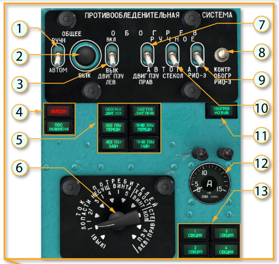
Trying to understand the purpose of 8, 9 and 11 in the picture: I understand that the radio-isotopic sensor РИО-3 sends signal to different parts of the system. The switch (9) does what? Is it supposed to stay down or up? What is the purpose for the pushbutton (8)? What does the indicator lamp (11) tell me? What is the procedures around these 3 items? Any hint to documentation will help. The only documentation I found now is about SO-121VM detector type.
-
... you can count me "in". :thumbup:
-
I was ready to mount the initial version today ... everything printed and refined. So I`m really happy that I waited and checked the thread before drilling holes in my Warthog. FD if you share the stl's for that one, I really owe U a drink.:thumbup::thumbup:
-
Yeah if you ask me I would opt for the solution just like the F18. Everybody who dislikes the additional detent button could choose not to activate the feature. This way everybody should be happy.
-
Running request - Bindable Button / Axis options
MFG62 Joker replied to maverickturner's topic in Bugs and Problems
I would like to suggest to add axis for flaps since now its only fully retracted or fully deployed. And: is the DLC thumbwheel an axis IRL? ATM it does not allow for permanently driving the LE controls to a certain state. It deploys an retracts the spoilers which results in a momentary effect. Maybe this is the real thing but I‘m not sure here. Anybody knows how this works IRL? Key/button settings for Throttle Mode ‚Auto‘ and ‚Boost‘. There is just no time in the downwind or in the groove to fiddle with the mouse in order to set throttle to auto. -
[NO BUG] Lack of binding to physical buttons?
MFG62 Joker replied to imaner76's topic in Bugs and Problems
This I missed also. How am I supposed to control maneuver flaps without being able to control the lever position aside from fully up/fully down :helpsmilie: -
At which PD are you?
-
[NO BUG] Lack of binding to physical buttons?
MFG62 Joker replied to imaner76's topic in Bugs and Problems
+1 Especially when using VR this is a killer! The reduced resolution of what you can see in VR (which is not HB‘s fault I admit) + museum-like weathered and hard to read labels in the cockpit + fiddeling with the mouse to get the correct click spoils the immersion. You spend way too long with your head down to be able to really control the tomcat. Mostly then the cat rides you instead of you joy-riding the cat. So please have a Look into that. -
PointCTRL - Finger Mounted VR Controller
MFG62 Joker replied to MilesD's topic in PC Hardware and Related Software
Great news, I hope to get one soon. Please ensure I‘m on your list. -
PointCTRL - Finger Mounted VR Controller
MFG62 Joker replied to MilesD's topic in PC Hardware and Related Software
Very nice product. Will be interested to buy as soon as it is sold. -
Tanker A/C TACAN and Harier
MFG62 Joker replied to MFG62 Joker's topic in User Created Missions General
For KC135: —> Advanced waypoint —> perform command —> activate TACAN Questions: A) For KC130 no option „activate TACAN“ is available. Anybody really managed to get TACAN A/C working on KC130? B) For KC135 Is there a loadout option to set a pylon with basket refuel system in order to let AV/8B gas up at a KC135? -
Want to train on Harier areal refulling. Tried to setup a mission. Works so far with KC 130. Would love to use TACAN to find the tanker but I ave no clue how to eiher set TACAN on a KC 130 or configure a KC135 with a basket pylon ideas anyboy please?
-
Lynx Cockpit Utility Brick "Button box"
MFG62 Joker replied to LynxDK's topic in PC Hardware and Related Software
G´day Lynx, great progress! Really like your stuff. Just wondering if you still plan to offer the DIY Button boxes or if this is off the table. -
Wow, I mean: simply wow! This is really great stuff!
-
... ist reserviert.
-
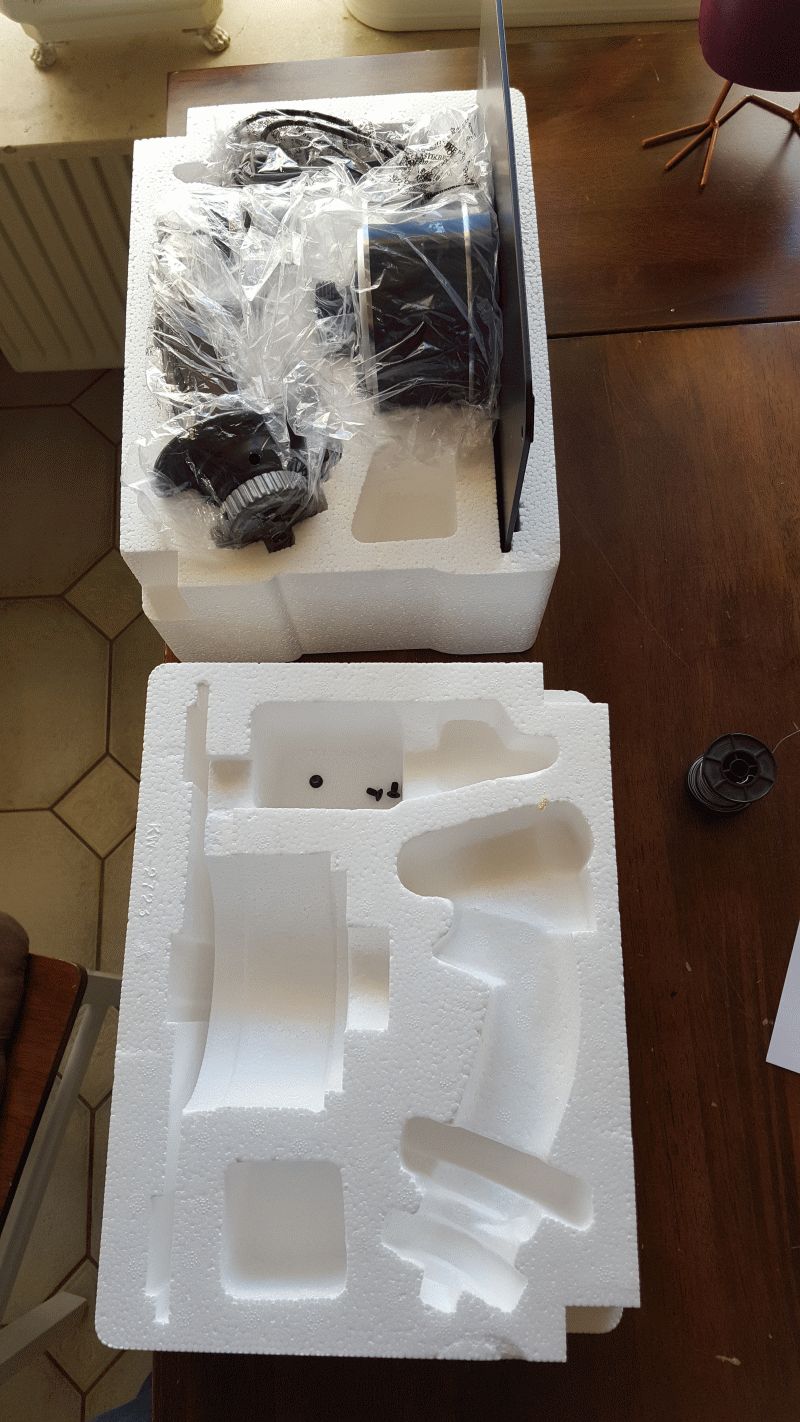
Hallo zusammen, mein Warthog hatte einen Kabelbruch. Wie sich herausgestellt hat war es mein Fehler. Ich hatte den Joystick zerlegt und gereinigt sowie neu gefettet (vor ca 1 Jahr). Dabei habe ich das Kabel für den Joystick Griff falsch eingezogen. Dass das Kabel erst nach einem Jahr gebrochen ist, zeugt von der Qualität der Kabel. Bei Thrustmaster habe ich ein Ersatzkabel geordert und eingebaut. Alles wieder originol und OVP. Da ich es nicht leiden kann gegroundet zu sein habe ich mir einen neuen gekauft, den alten, reparierten möchte ich jetzt verkaufen. Preisvorstellung 120€ incl Versand in DE. Bei Interesse bitte PN.
-
Lynx Cockpit Utility Brick "Button box"
MFG62 Joker replied to LynxDK's topic in PC Hardware and Related Software
nicely done! Will we see an option for rotary encoders? Remember: for an VHF/UHF radio-CUB one would need them :smartass: I´ll wait for the DIY box, then count me in :thumbup: -
Post pictures of your setup.
MFG62 Joker replied to SierraFox's topic in PC Hardware and Related Software
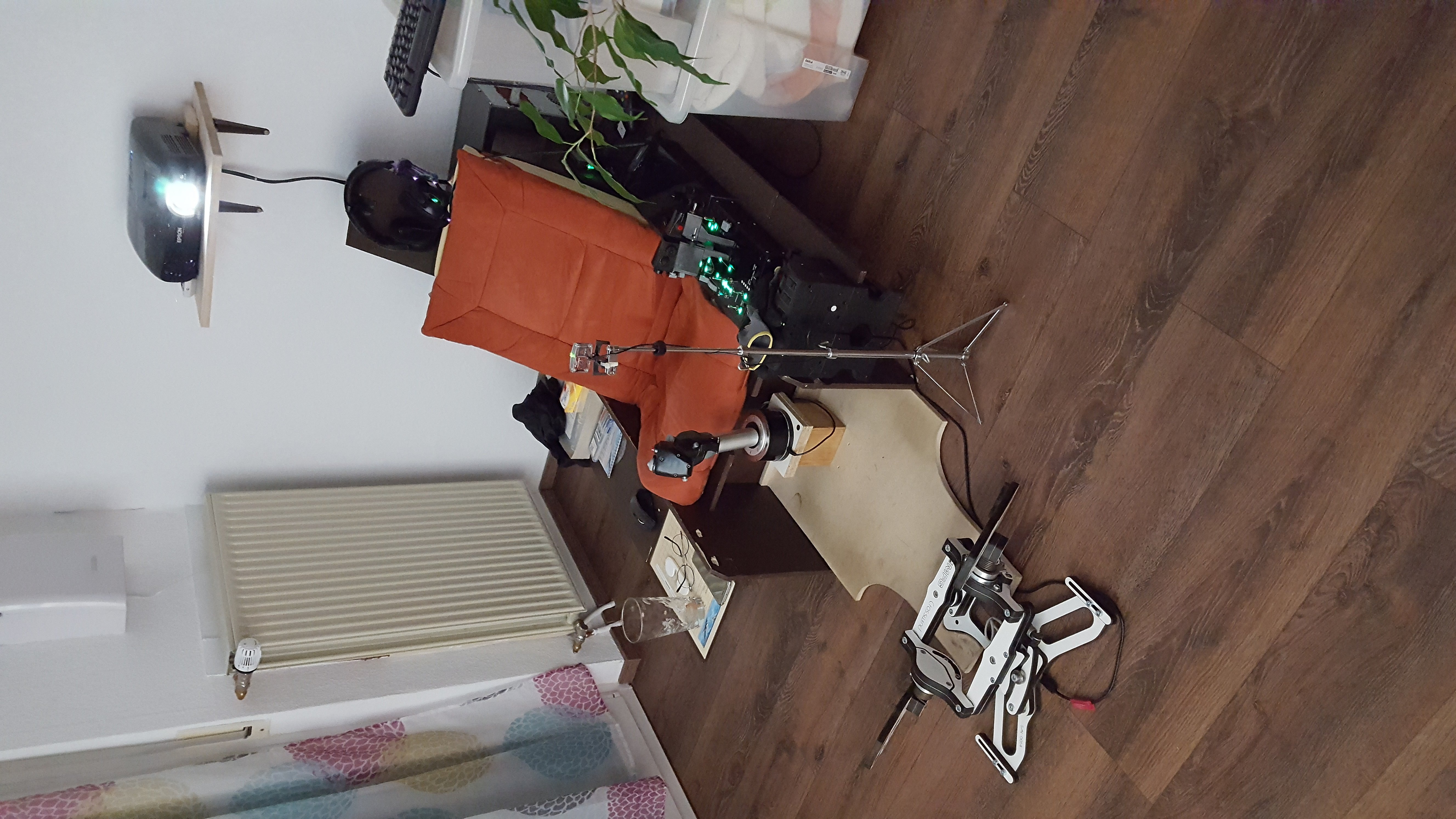
her we go ... :joystick: