Hempstead
-
Posts
472 -
Joined
-
Last visited
Content Type
Profiles
Forums
Events
Everything posted by Hempstead
-
I’d like to know the answer to this “problem” too. You ain’t alone, OP!
-
Talk about messed up control defaults. For YEARS, I thought DCS was just ridiculous with its flight model. My P51 and A10 would just bank left hard, invert, and dive whenever I pull the stick back a bit hard. Come on, prop procession isn’t that bad! Not on real Cessna, or Piper! Sure, P51 is a very powerful plane that I have never flown in real life, but this is some ridiculous banking that requires an uncle Chuck in order to just cruise, let alone fight. Not everyone flies the X-1, you know. Oh, and the A10 is a twin jet. There shouldn’t be any prop procession! So, I never really got into DCS, and wrote it off as a bad investment! Those are the two cheap modules I buy to try it out. Didn’t work out…. Move on. I even offered a cast bronze F16 TQS as the reward to a local fellow simmer friend to fix it for me. He didn’t take it, after I described the symptom to him. I finally figured it out myself. For some reason I could never understand, the damned thing would automatically assign all controllers it detects with X, Y, Rz to roll/pitch/yaw, including the damned mouse’s! Oh, and my Razer optical keyboard, and keypad also emulate joysticks. And vJoy joins the party too! All of them! So I would end up with multiple controllers all trying to control roll/pitch/yaw. And it would not manifest until I pull back on the stick a bit hard. So, I would take off ok…. And fly around, land fine…. But as soon as I tried any “maneuver”, it would bank left hard and dive! What? No split-S, you stupid plane! Haw, haw haw…. Old timers are probably laughing their rear ends off… everybody knows that, you rookie! Well, never in my wildest dream would I dream of programming it to assign all controllers’ X/Y/Rz to roll/pitch/yaw. There is the right way, the wrong way, the army way, and there is just the idiotic way. There is just no bloody reason to spend that extra effort to default it wrong! What are you trying to pull? Screw with new customers? And trying to discourage players changing/adding controllers? What for??? So, that was the last place I would have ever looked! Come on…. Nobody would…. Worse… every time I plug in a new controller, it detects and assigns the new X/Y/Rz to roll/pitch/yaw too! I plug in my Saitek yoke I use for flying 787 in MSFS 2020, my DCS F16 starts banking/rolling unintended! So, every time I add a new controller, I would have to go in and clear every single plane’s X/Y/Rz for the new controller. WTF? Even worse, I write my own USB firmware for controllers, so I often have “new” controllers to try out! This just drives me nuts! Come on, ED. Stop this auto-wrong!
-

Magnetic Base (HOTAS Warthog) replacement potentiometers
Hempstead replied to Bergison's topic in Thrustmaster
Thank you for your kind words... @rel4y I didn't know any simmer is using it. I know a small commercial company was (is?) using it for their sim controllers, and a Brazilian company was (is?) using it for controlling ROVs. Other than that, I know nothing. No MLX90363 for Hempstick incoming. But the good news is... I am contemplating on writing Hempstick Pico, a complete rewrite from scratch for RPi Pico (maybe even RPi Zero 2 W). It may take a long while... my goal is force generators for my own controllers (the bronze casting of F16 TQS for instance.). So, timetable is on the progress of my own controller prototypes (stick, throttle, and rudder all); i.e. when I need it, I will write it. Moreover, I am "busy" with DCS F16C. OP, sorry for hijacking your thread. -
Magnetic Base (HOTAS Warthog) replacement potentiometers
Hempstead replied to Bergison's topic in Thrustmaster
No can do! It's an MLX90333 running in 3-wire SPI mode, instead of analog 5V mode, or PWM mode, like rel4y guessed correctly. That's why it's 5 wires... dead giveaway, Vcc, GND, MISO/MOSI, CLK, and CS. In PWM or analog mode, it would be 4 wires, Vcc, GND, X, and Y. -
Actually, this is the worst casting of the 4 sets. There were voids in this set, and I almost threw it away due to the casting defects. But I figured I could use it as a "tech testing" piece using different tools/techniques on it before using them on the other 3 sets. For instance, would 100A DCEN on the TIG welding work? Yes, kind of, and my TIG welding skill sucks big time, but my sanding skill is plenty good enough to cover that shortcoming. As you can see in the picture below, it's not perfect. There is a little gap between the upper and lower main body, and there are still some small holes in the screw hole. But it looks great and feels great in my hand too. Well... I am an amateure, I can happily live with such results. I am currently working on the guts of this thing... among other things, the optical HAT switch, mini-Hall sensor, and the controller (not necessarily based on Hempstick). But you see where I am going in the LONG run. The 3D model is just one of the first steps... the least "valuable" part of this "long run." I would have shared all of them OpenSource (I am going so far in compiling Linux kernel myself, writing Linux kernel drivers/modules, and learning Yocto to get my own Linux distribution, etc. etc.), but unfortunately, somebody has to violate the OpenSource licensing terms. So, now I can't figure out how to share without getting my shit stolen.

-
The attached are pictures of the inside of the F16 TQS. The first one, the black one, is the real one with all the parts. Although I didn't really model the inside except the 3 "islands" for accepting the screws, it's in general quite "close" to the original with some small modification for modeling convenience. In general, I used 0.1" thickness and tried to keep that thickness everywhere. The 2nd picture is the result of my bronze casting of it (chopped it up in multiple pieces for easy casting and extraction, 3D prints, silicon RTV mold, and then traditional lost wax casting process, and TIG weld them back together... and a lot of sanding.). The inside of it is very close to the real one. Why bronze? It's the local Pratt Fine Arts Institute, where I took class and cast them. Artists do bronze... they don't do aluminum, so I observed Pratt is a Fine Art institute. And I actually quite like the extra heft of bronze, and this thing would never get off the ground, so weight is not an issue. And don't ask... Although I cast total of 4 sets, in anticipation that some would fail, I lucked out and ended up with 4 sets. I will not sell this stuff. It would a violation of LMCO's copyrights.
-
Instead of claiming wild theories from a post that got deleted by admin on ViperPits, please point out anywhere else have I ever demanded royalty. Even the PTFE rings I sell here, I barely stayed black. I view it as a community service, b/c if I factor in my labor... it would be at least triple the price. Oh, and I posted the full spec. of the PTFE ring and told everybody who wants to make them for profit, please let me know, I would refer business to him/her so I can get out of the community service.... no takers so far... one British cloner... but you don't see me complaining about not getting credited. Even on ViperPits, I made it abundantly clear that I would grant a personal commercial license of the 3D model files to my fellow ViperPit members, at the fee of whatever you feel appropriate, in the form of donation to ViperPits.. The purpose of that was to take the money question out of the equation, yet at the same time prevent big commercial companies from swooping in and take everything without crediting the works by the flight sim community. Where and when did I EVER demand any royalty? Plus, all those 3D models except those by Kumrik, which are clearly marked out as exception, were created from scratch by my own two hands. Even as today, you can still see that exception on GitHub, in the form of Copyright.txt. All 3D models published here are released under Creative Commons Attribution-NonCommercial Internationl, v4.0 license. All rights reserved. Jonah Tsai, 2014-2015. Exception: Copyrights of files under ButtonsKnobsLights/Knobs/Kumrik Knobs/* belong to Kumrik of ViperPits. They are also published under Creative Commons Attribution-NonCommercial International v4.0 license. https://github.com/JonahTsai/F16/blob/master/COPYRIGHT.txt Please point out which part got on my hand that was donated! I never received any parts from anybody without paying big money for it, not even as on loan for measurement. I know I way overpaid for a lot of them, particularly those ones I bought from one of those ViperPits admins. In fact, a VP admin lives just 2 blocks away from me and he owns a FAM pit. I asked to go measure some dimensions from him and received a cold shoulder of silence. Great help, eh? Except those from Kumrik, I did paid literally thousands of USD in purchasing all those genuine F16 parts out of my own pocket, nobody else's money. Yes, indeed a couple of parts I did purchase from the ViperPits community at exuberant markup (You think I didn't know I over paid? Think again. ;) But I wouldn't qualify that as community helps. I did create all those 3D models by my own two hands, except those by Kumrik. Every single line of in those 3D drawings were put down by me. I have the GitHub repo history as a proof of the progress, published all in the open. You can go check them out yourself -- every bit of change is recorded in GitHub commit history. And I have never ever laid eyes on any F16 blue prints. Every time I saw LMCO name on any drawings some dumb ass posting on ViperPits, I shake my head and close it immediately. I don't want to be contaminated, in case someday some dumb ass would come claim I copied from any "blue print." The only helps I received from the ViperPits community are the followings: 1. A couple of corrections and feedbacks. These are all documented in the 3D model thread on ViperPits. Go read them and see how "many" helps I got from the community. Not that many really. 2. The TUB model... all the dimensions were from Feather's annotated photos and spreadsheet. This is clearly attributed to Feather's credit. All I did here was translating his dimensions to CAD models. That was the extent of my works on the TUB model. And it was clearly attributed. 3. A couple of dimensions for the HUD models that I wasn't sure about the resin cast I paid over USD$1000 for, so I crossed checked with a 2D drawing I found on ViperPits... I can confidently say 99.9% of the dimensions of the HUD model came from my caliper and 100% of the 3D modeling was my works. 4. A lot of encouragements from ViperPits. But.... all those 3D models were constructed by my own two hands, every single line. I don't know about you... I qualify that as files 100% created by me. Let me put this abundantly clear. It's people like you that I stopped publishing anything for free. Instead, I am giving out things for free to only people I trust. That's where you are completely wrong. Let me repeat again -- I don't own any of the design copyrights of those F16 parts. Lockheed Martin (LMCO) does. I only claim the copyright of the unique combination of the step-by-step construction in the the 3D model files, which if you just open those files in any compatible CAD you would re-execute those steps I created in order to reconstruct the 3D models, and claimed copyrights. I never claim any copyrights of the designs. You make a part for sale out of those 3D models files, first of all you violated LMCO's design copyrights because you just cloned LMCO's product for sales not because you used my files, unless you took out a license either from LMCO or US Air Force, like ThrustMaster did. But that's between you and LMCO, none of my business. All I am concerned is that I published those 3D model files under Creative Commons Non-Commercial International license, so if you used my files to make profit, you clearly violated the "non-commerical" clause. That is very uncool, whether you agree with my claim of copyright or not. That is not how a community should be. If a community steal from each other in the open, perceived or not, who would share? The bottom line is very simple. You don't satisfy my no-stealing demand, I won't publish more. It's that simple.
-
HOTAS Warthog and the o-ring
Hempstead replied to Daniel's topic in PC Hardware and Related Software
Thadiun, Go ahead, knock yourself out. ;-) As I said, I only do the PTFE rings as a community service, making no profit at all. So, if you want to make them and sell them, I'd gladly bow out. There are PTFE sheets that are made one side bondable. I have experimented with them as well. The original idea was actually a very thin 1/32" thick PTFE one-side bondable sheet, with an 1/32" thick aluminum or steel ring for stiffening to make it almost exactly the same thickness as the original rubber O-ring. Couple of problems with that prototype. 1. Even with epoxy, the bond eventually delaminate. 2. The 1/32" thick aluminum or steel ring is still too thin, they buckle easily. So, they still need to be glued down. That defeats the whole purpose of the stiffening ring, as glue eventually get attacked by the grease/oil (depending on the kind of grease/oil you use, and you know some clueless will use WD-40; and I have actually heard somebody did it). The composite ring is particularly prone to de-lamination when the ring is bend. And that's exactly when you actually need it to stay bonded. I found out the hard way that to prevent this problem, you actually have to up the total thickness to about 1/8" for the composite ring. But, I also found out that at 1/8" thick, a solid PTFE ring at 1/8" thick would do that job by itself. So, no point of doing the extra busy work of using a stiffening ring that ups the costs and works. ;-) -
HOTAS Warthog and the o-ring
Hempstead replied to Daniel's topic in PC Hardware and Related Software
Thanks for your kind words, Weegie. Just wanted to add a little clarification. On page #2, there is the full spec. of the PTFE ring. You are free to make as many as you wish and sell them too. If you do sell them, please let me know, so I can refer to you and get out of this community service. The ring is made out of the most common grade of 1/8" thick PTFE sheet (yes, there are several grades of PTFE, including Teflon AF, an optical clear PTFE). 1/8" is slightly "too thick" and indeed interferes with the most extreme deflection of the stick just a hair. However, I chose this grade of PTFE with the thickest possible thickness so that it can: 1. be stiff enough to wedge itself in position without the aid of glue, 2. have more "meat" for wear, and 3. this grade of PTFE is softer than the ABS (?) of the gimbal, so the PTFE wears but not the gimbal, if any. The next thickness, 1/16", I can get is too thin and provides not enough stiffness so it would require glue or double sided tape. That would have gotten you in the same problem like the original rubber ring -- glue failed and the ring got out of position and got pinched. However, the PTFE I use is soft enough such that after about 1 week of uses, it will form a ring of shallow depression groove due to compression and reduces the effective thickness and you get back the full deflection. The change of effective thickness shouldn't affect the calibration to the degree that you can feel it. But, it wouldn't hurt to re-calibrate often. -
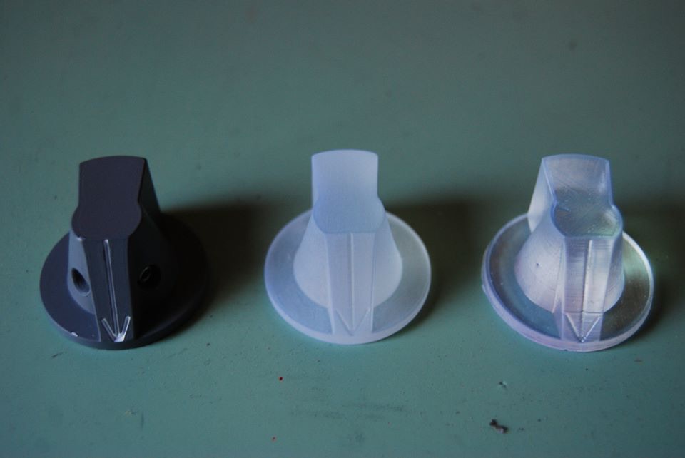
Lowest resolution output of my SLA printer. Left, the real one, brand new. Middle, lightly sanded, and glass bead blasted. Right, right out of the printer, alcohol washed. Didn't even bother to go higher resolution. After UV cure, it's hard as nail. SLA printers are still expensive, ~USD $3,000, and the process is still not ideal. But, they are slowly becoming viable.
-
I am done here. Have fun!
-
That would be your freedom to do so, man! Then, don't share! It's also my freedom to spend thousnads of USD on authentic parts, then spend countless hours meticulously measuring the authentic parts to construct these 3D models and then give them away free of charge, as I prefer not to turn myself into a minimal wage worker making peanuts. Damn it, it's a hobby! Not a job! Don't turn a hobby you enjoy into a job, because once it's a job, there is no fun in it! You see why I treat the PTFE rings as a community service, and I actually only barely stay in the black? It's a hobby, not a job! If it's a job, I'd have to charge $20 apiece and you would have no choice but to pay up when your $500 joystick broke, or make it yourself, or contact TM to get a relacement rubber ring which is bound to break soon. If it's a hobby, then share! That's my take on it. You are free to disagree! Some would prefer to buy your faithful replica with minimal fuzz, some others would prefer to make them with their own hands, given they could get their hands on the information. Each to their own! I just prefer to give people all the information and let them go "hog wild" with it and then come up with something better than I could ever do! Once people downloaded the 3D models, they don't need me anymore. Call me a Hippie if you like even though I don't wear a flower in my hair in San Francisco, I prefer free flow of information.
-
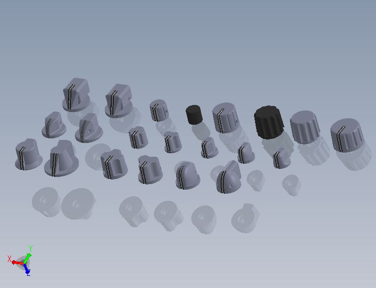
Attached is the image of the 22 knobs set Kumrik sent that will be published later. These are indeed F16-centric. However, the point is that he constructed these out of EHC spec sheet, without physical knobs. They are damned good! I am sure there are some errors here and there, but I haven't found them yet. I am pretty sure they will work very well if you were to 3D print them out with SLA 3D printers. The point is that if Kumrik can make these knob 3D models out of the EHC spec sheet, you can do the same to the A-10 knobs too. If you do 3D model them, please consider sharing them!
-
Kumrik has sent me a bunch of knobs 3D models he constructed from EHC specsheet. They look pretty good! We are planning to put them up on the Hempstick Flight Sim 3D model pages. These are good for 3D printing. If you have SLA printers, they print out beautifully. After a bit sanding and painting, you would be hard pressed to tell them apart! Note that, nobody says you can't mold the print and cast them out of resin (although some photo resin inhibits some RTV). If your printer can print multiple knobs in one go... unless you need a lot of the same knobs, casting isn't exactly time saving (might be cheaper). For instance, my SLA printer's software allows me to lay up multiple different knobs in one go. So, even though it takes about 40 minutes to print. I can get 9 knobs or more in one go, and each can be a different model of knob! That is, all the knobs of a panel in one go. Stayed tuned, the new knobs models should come up in a few days time.
-
I don't know if it's available in UK. I use SuperLube, a PTFE-based synthetic grease.
-
Can't say it in public. Otherwise, I could get sued for defamation, partucularlly when CougarWorld, the site I posted the idea, is down, i.e. can't even defend myself. I live in the land of the free, got to watch out for law suits that could ruin you fonancially.
-
I agree that's indeed the case. I figure it's because the posts and holes are not perfectly aligned. So, if you rotate the platform relative to the posts, i.e. make the holes mate w/ differrent posts, then you get tighter or loser mating, resulting in more or less dead center. Of course, I could be totally wrong on this reasoning/hypothesis. But i think sharing the reasoning behind why I think so is more important than the end result. If the hypothesis is correct, then it stands to reason that there is one direction (1 of 4 possible permutation) that is tighter than the other 3! Therefore, you should try to rotate the platform and get the tightest one!
-
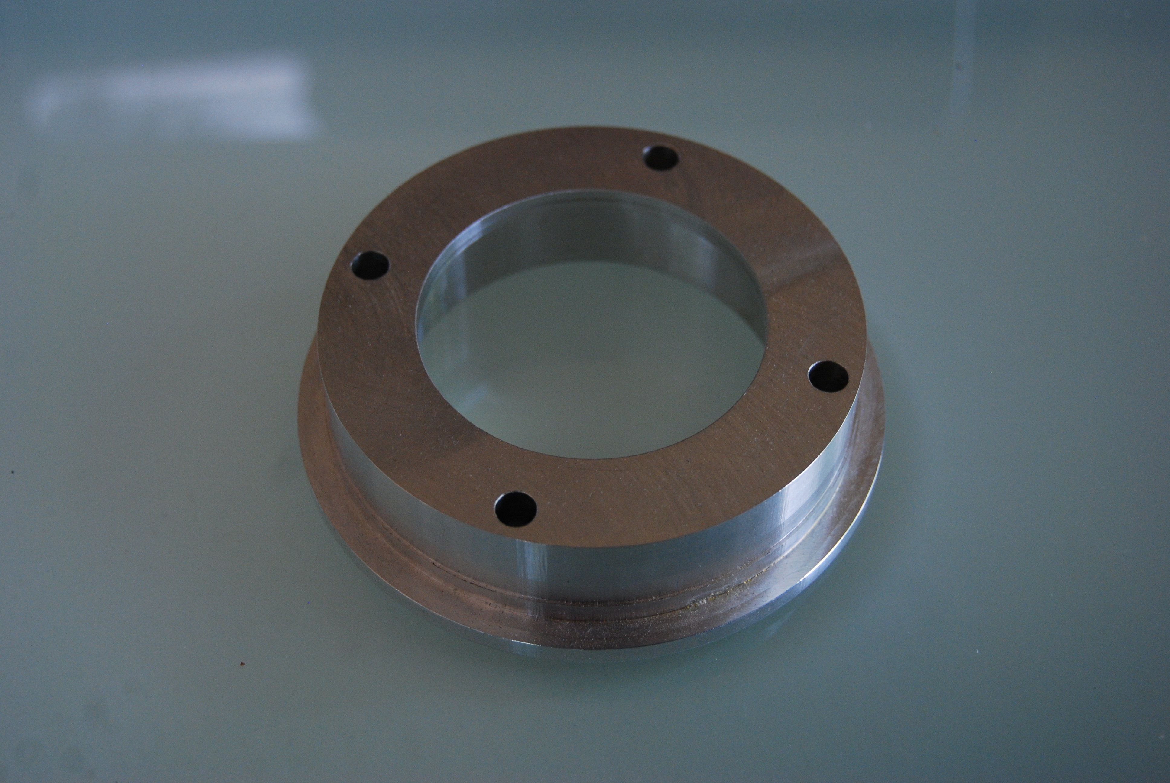
I posted the following findings long time ago on WarthogWorld before it went down. The dead center on Warthog is only dead center for the spring force, not the sensor measurement. The sensor will still accurately pick up the stick movement inside the dead center zone, as Shadowlin pointed out. However, I think the dead center is mainly caused by the 4x holes for the 4x posts being tapered, not because the holes are larger than the posts (the holes on the white plastic being bigger than the post obviously would make that worse, but even if it's not, you would still have dead center). If you look carefully, you'd find that the hole diameter is slightly smaller than the bottom, i.e. the cylindrical wall of the hole is not exactly cylindrical. I didn't notice that before I went on to mill a "perfect" spring platform out of 6061-T6 aluminum, see the attached picture. I thought the same thing, that the holes are not accurate, so I set out to CNC mill this thing out of a solid chunk of aluminum, and accurately drill and ream the 4x holes to be exactly 5.01mm, to tightly fit the 5mm diameter posts. It took hours to accurately CNC mill this thing front and back out of a solid chunk. The result was a "spectacular" failure -- the precision reamed holes bind the 4x post as soon as the stick is moved, i.e. the stick now does not move at all. Upon close inspection, I find that as soon as the stick is tilted, the rim tilts up on one side, contacting the platform at one point (through the PTFE/rubber ring). Then, naturally, the platform wants to tilt too. The 4x posts are there to "guide" the platform up and down and prevent tilting. But, if the 4x holes are as tight as I made them, each post will contact its corresponding hole by two points only, one on the top, and one on the bottom. This causes great pressure between the post and the hole, thus binding! I am quite sure TM found this problem during prototyping and they solved the problem by tapering the holes, making the contact area bigger so no binding. But the consequence is the slight dead center of spring force -- the platform has to tilt slightly before moving up and down. I am designing a new gimbal mechanism that has no such dead center of spring force, and might be able to adopt this mechanism to Warthog. However, this time around, I might want to patent the idea if it works well. So, some commercial company can't just take the idea and run with it and beat me to the punch without even acknowledging the idea's community origin, like last time. But even if I patent it, I will let the non-commercial use by the community use it for free. Don't hold your breath on it though. It's not urgent and I have so many other things to work on. It will take months (oh, it's already been months since ... ;-)
-
Again, please DO NOT superglue or epoxy the old ring or any ring in. This ring is consumable. You permanently glue it in, then how are you going to replace it when it wears out? Clean up all the grease and double side tape it back. Or buy a PTFE ring from me, which requires no gluing. Just slide the PTFE ring in place, grease up, reassemble and go. I view the PTFE ring thing as a community service, so I am only charging USD $8, s/h included. Just enough so I don't lose money on it.
-
Rudder Control: Twist Stick vs Pedals
Hempstead replied to Visceral Raptor's topic in PC Hardware and Related Software
There are reasons why most of the modern aviation controls have "standardized" yaw control with foot pedals. Didn't used to be at the dawn of aviation. The Wright brothers used their hips for yaw. The main reason I think is human physiology. Like MetalWood said, twist action of your wrist is just not as precise as your foot work. And more importantly, it's almost impossible to move in the pitch and roll without affecting yaw if you have a twist stick. That is not exactly a desirable trait when you are trying to fine tune your aim at a target. It's particularly bad when you fly a chopper and trying to aim some rocket pods at ground targets. Also, when under stress (say bandit at six with radar lock on you), humans tend to use actions that are more natural to their physiology. With a twist stick, you tend to turn left more (for right handers) than right, because it's a lot harder to twist your wrist right than left (try it if you don't believe me, and then center mount the twist stick and try it again). I tested this theory when I was teaching a buddy to dog fight; it worked like a charm -- he "always" turned left when I got the radar lock on him (he's right hander with a twist stick!); and I would be waiting there for the kill. Then only tell him when he got frustrated. Now, he would never forget that lesson -- don't use a twist stick! ;-) I am not saying twist stick is such a big handicap. There are people who are very good with twist sticks. But in the air I will exploit any weakness. If you hand it to me, I will certainly take it! And, thank you very much for being so nice in a dog fight! -
It is, unless you can find a ready made pot with long step cut shaft with threads on it and have tools to cut metal. Or you can use something like this, PTR902-2015F-C104 on Digikey. Since this is controlling light brightness, it needs to be logarithmic taper.
-
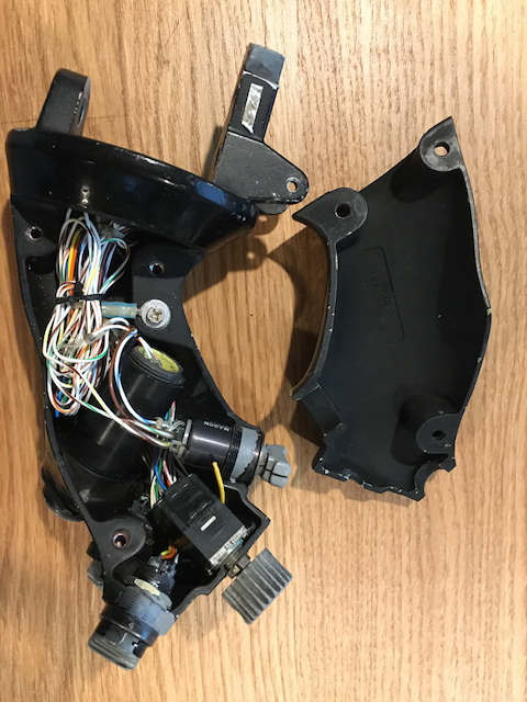
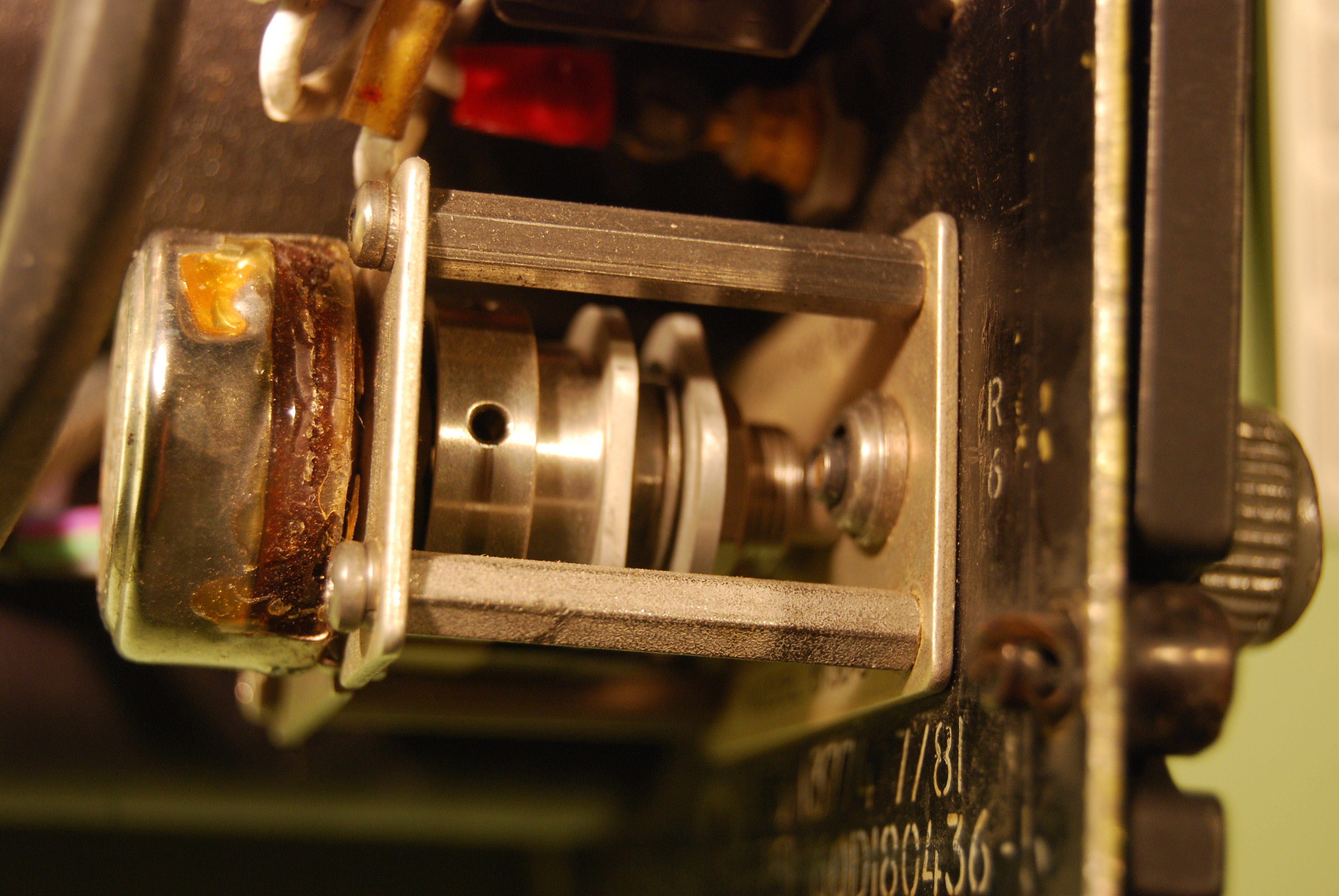
Here's how the original's Flood light works see the picture, you can do the same, similar to DM says for the Flood light. The original flood light electronic is a variable AC transformer with a off position built in but that's irrelevant to us. In the picture, from the left to the right. 1. Pot (made in Mexico. ;-), 2. a aluminum disk with a drilled hole and a pin to create the click at "off" position (no electronics here). 3. an aluminum disk with a flat notch and a microswitch to trigger the off signal, 4. another aluminum disk with a flat notch and a microswitch to trigger the T Storm signal.
-
Possible problems in TM warthog
Hempstead replied to rami80's topic in PC Hardware and Related Software
I'd still be interested in seeing why yours wear out too! How about this... send me a PM with your name and shipping address. I will send you one for free. Let's see if we can find what's causing the wear. -
Possible problems in TM warthog
Hempstead replied to rami80's topic in PC Hardware and Related Software
You wear out the PTFE ring I made? That would be the first. I would love to find out the condition that wears it down. If you could, pictures please? . -
Are there still people making/selling panel face plates?
Hempstead replied to TigersharkBAS's topic in Home Cockpits
Very much agree on that point. Look, it's a home flight simulator. The more details the better, but there is a point of diminished return. Even if you are building a real replica that can take off, there is still a point of diminished return. I ain't going to spend 10 years collecting all the authentic measurements. That's just me. But to some, that's their "hobby", it's their pride and joy collecting this stuff (I collect the useless state quarters. ;-). Great, each to his/her own. If you would share that info collected over the 10 years period, I'd greatly appreciate for saving me a lot of time! Hey, if you publish a book, I'd even be glad to pay for it! That point of diminished return is different for everybody. To me, it's not worth my time chasing down the last detail. I am not even interested in building the whole pit. I only want some panels that matters to me in the air. Lighting control panel is NOT one of them, but that's the only one I can get on eBay and it serves as a good sample to see how real panels are made and emulate "as close as I CARE." Note that, NOT as close as I CAN. I am more interested in the real function behind them that gives me an edge in the air. That's why I wrote Hempstick because after I got the panel to my satisfaction, I couldn't find a suitable controller to drive it, not even for a freaking simple lighting control panel that does not give me any edge in the air! All the commercial controllers I could find are not extendable, and the extendable ones are Arduino crap; none of them meet my criteria (I care more here, not there!). And, except one or two controllers, all use extremely outdated MCUs. Without good controllers behind these... to me, it's just a good light show; useless to me. But to others, that might be good enough. Hey, everybody values different things... If Arduino is good enough for you, it's good enough.