Hempstead
-
Posts
473 -
Joined
-
Last visited
Content Type
Profiles
Forums
Events
Everything posted by Hempstead
-
 Thanks man! I tried it with my Quest Pro. At first it didn't work, but then I followed the exact procedure to unplug OculusLink, clean out the fsx and metashader2 directories, and reboot, etc... and now I get very stable 45fps and the frame time is pretty solid (I fixed it at 45). Before, I got mostly 45fps, but at low alt. and near Vegas buildings, I get 30, and a lot of constant spikes on the frame time, like periodical spikes, one after another. Now, after, the frame time history is like a straight line... sure, occasionally, there are spikes when I approach some new buildings... but it's mainly just a flat line. Even on the ground at Nellis, I get quite stable 45fps. Great Improvement. Again... Thanks a lot!
 -
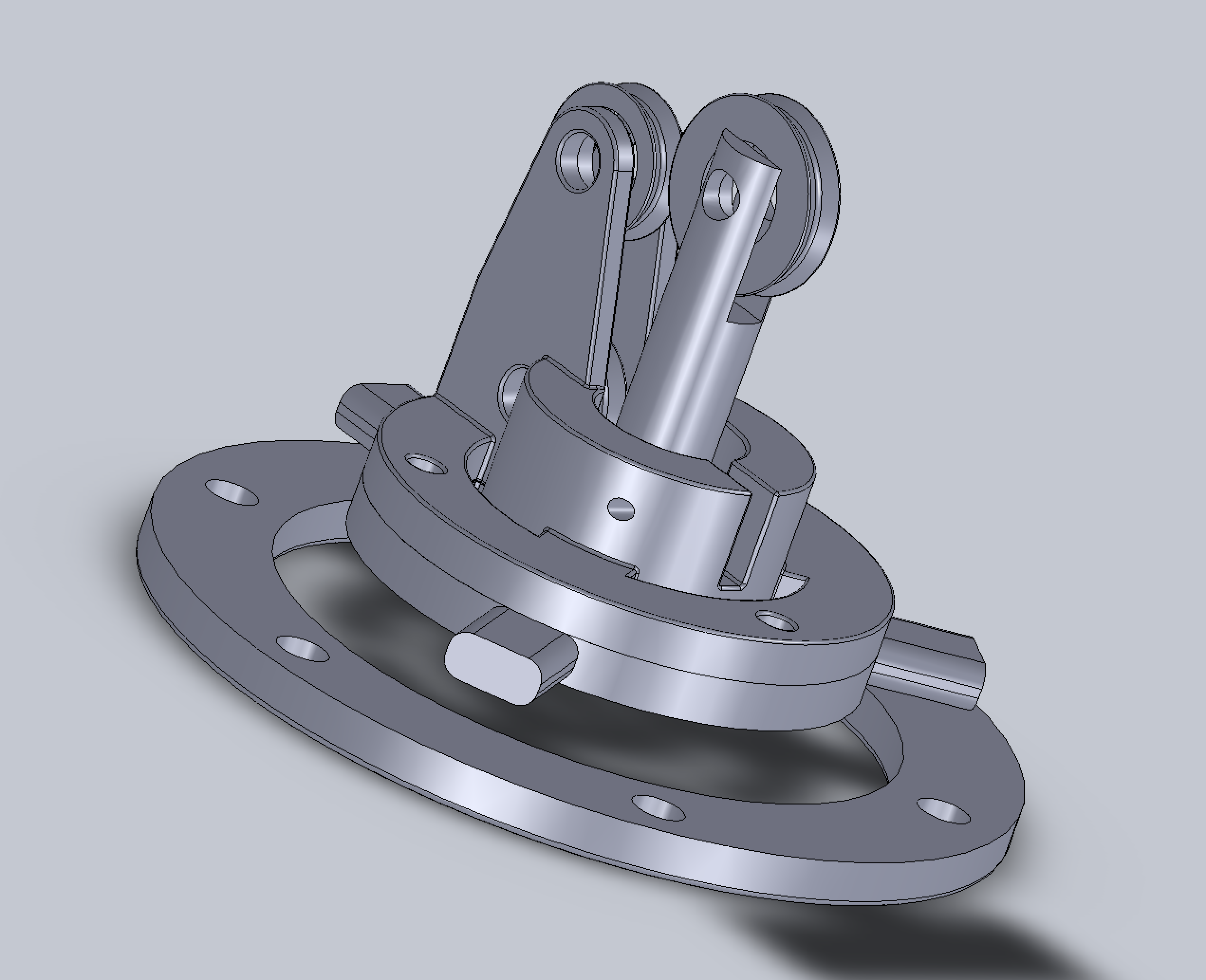
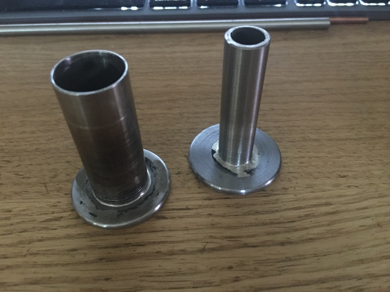
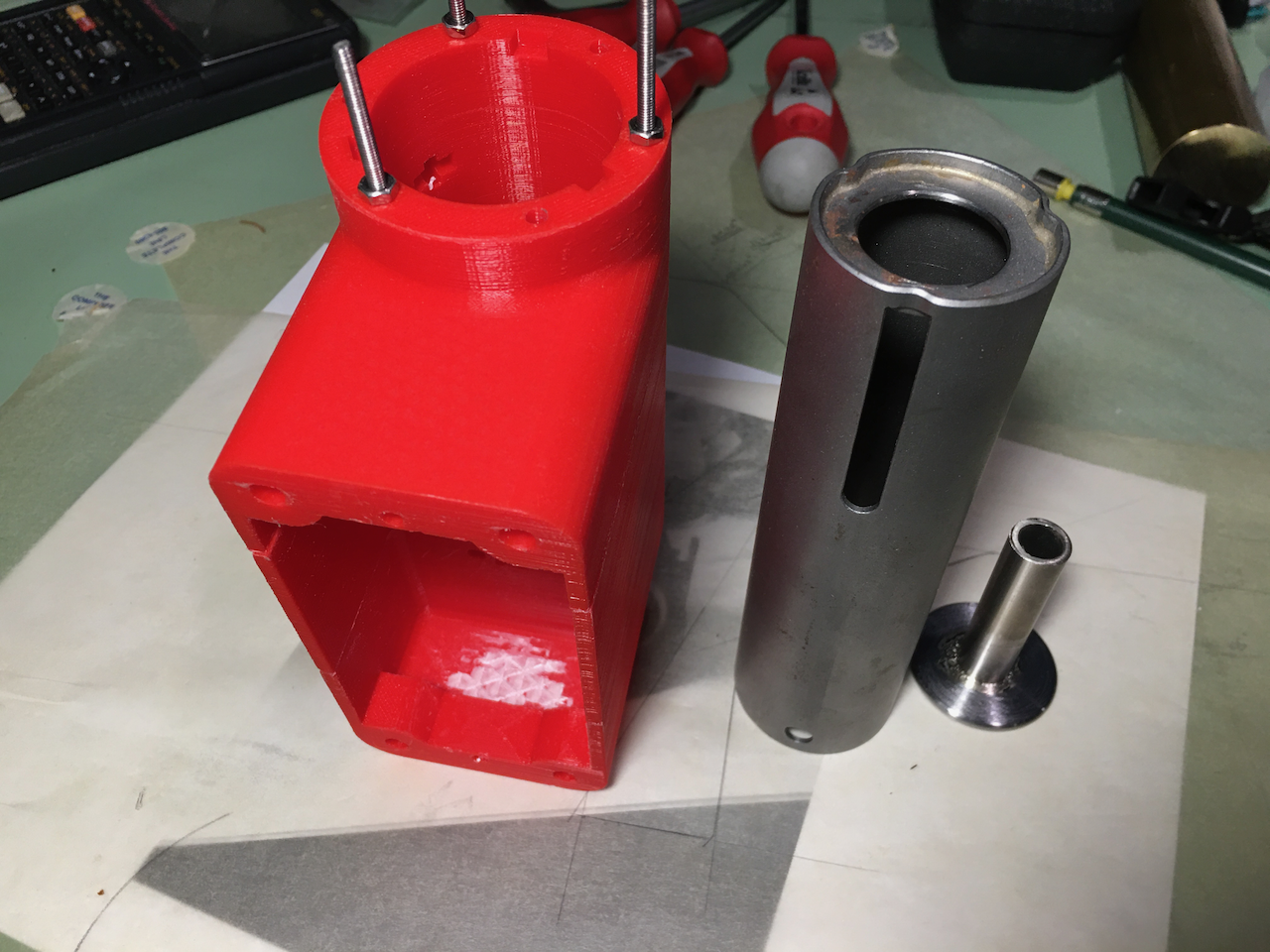
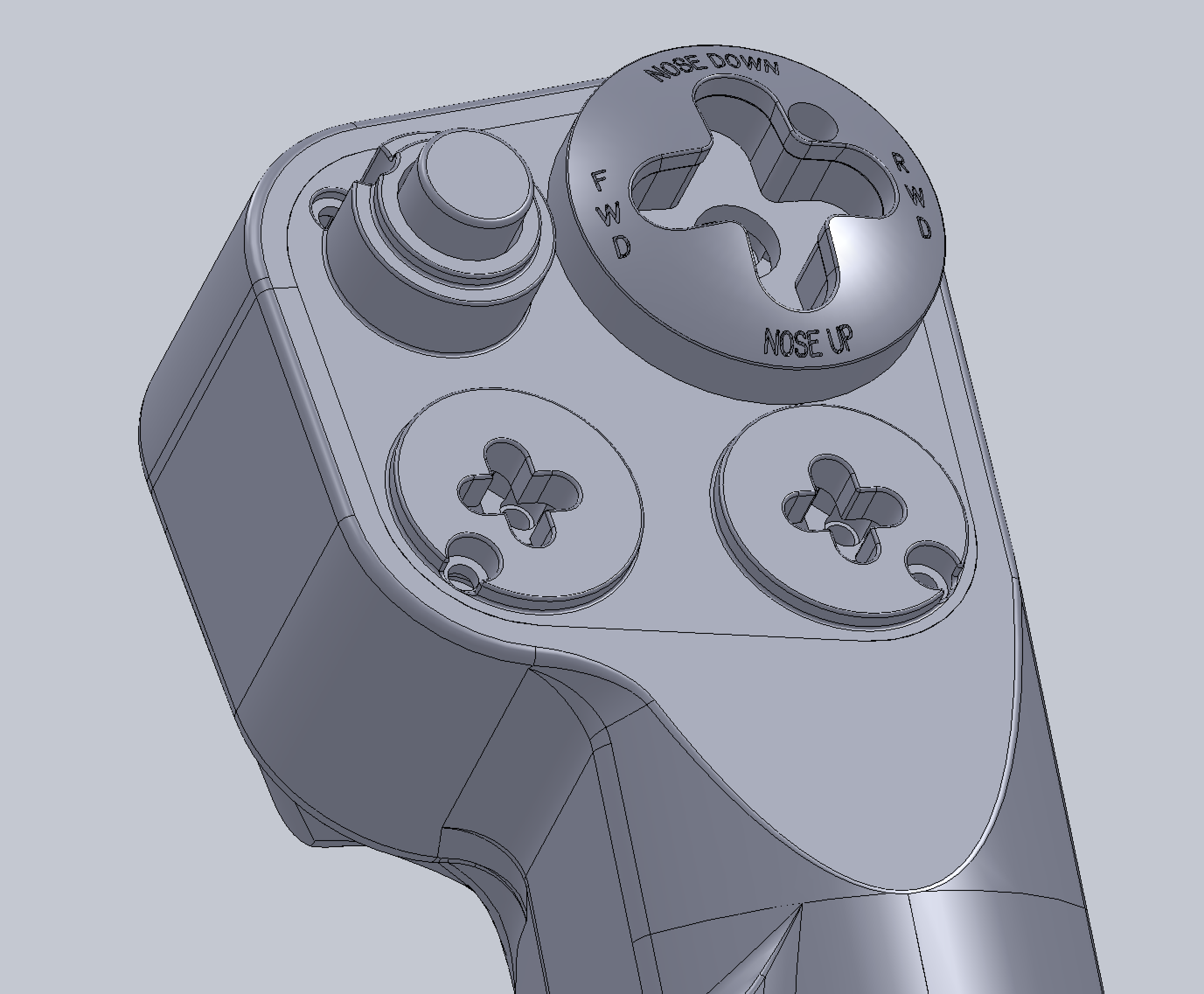
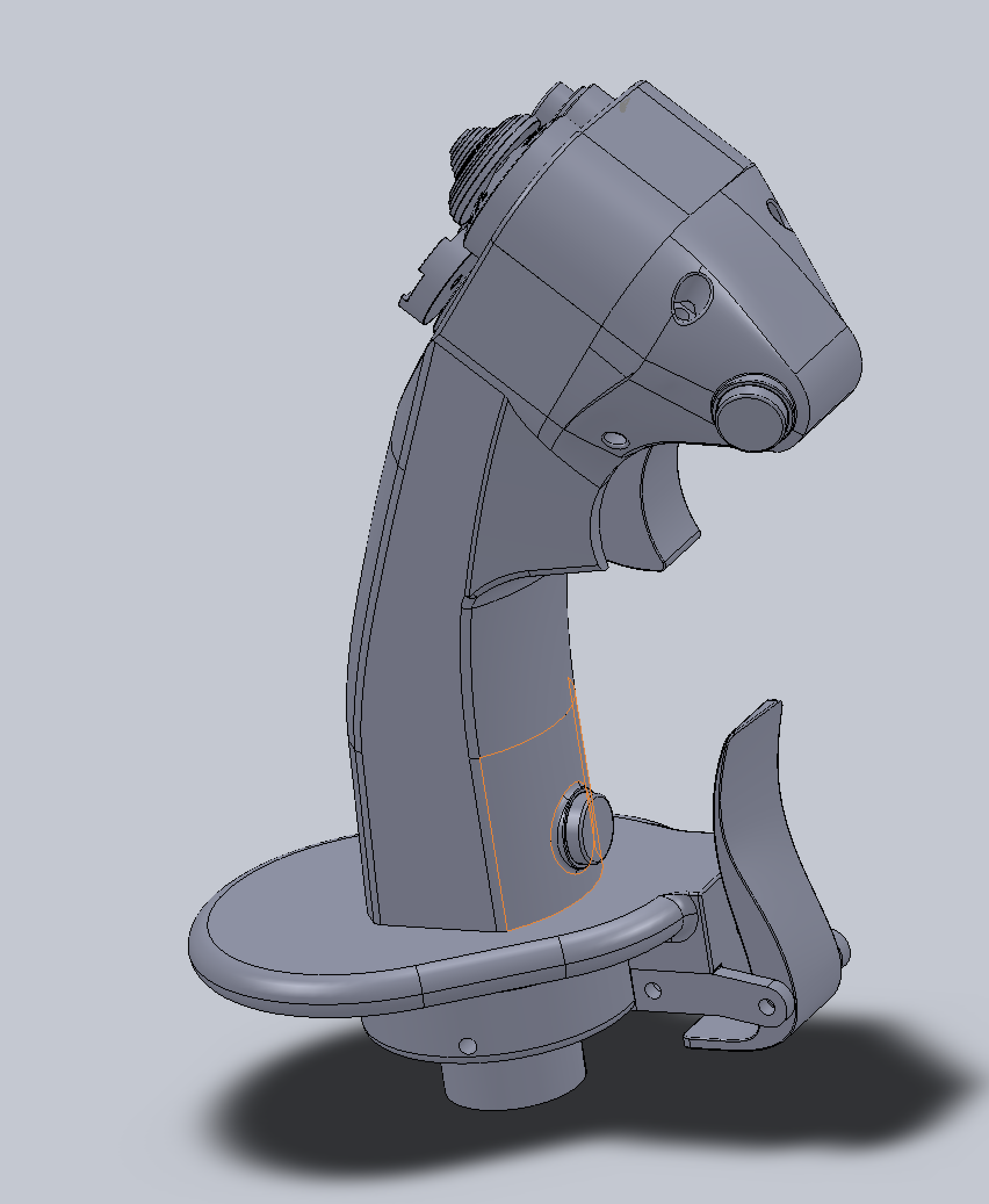
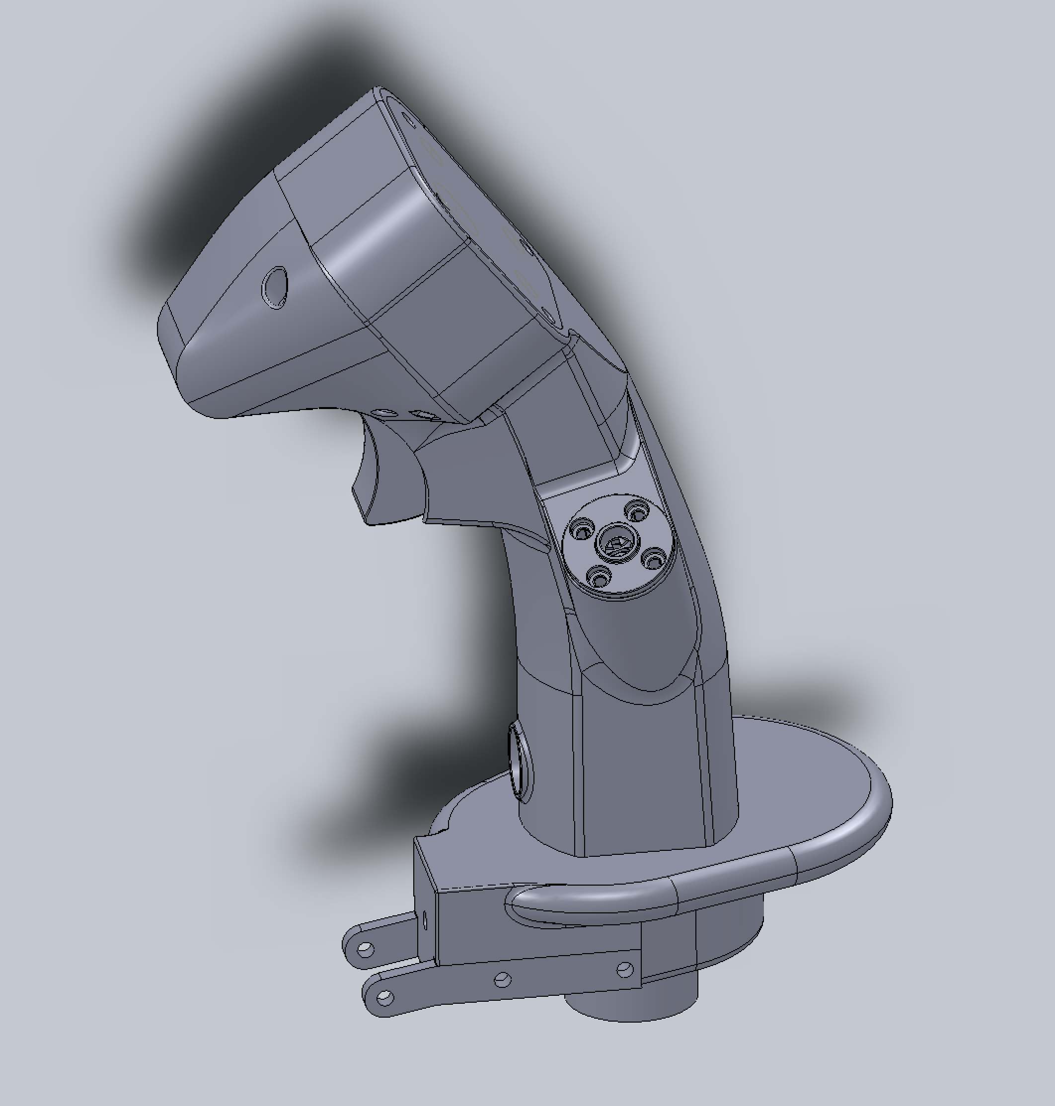
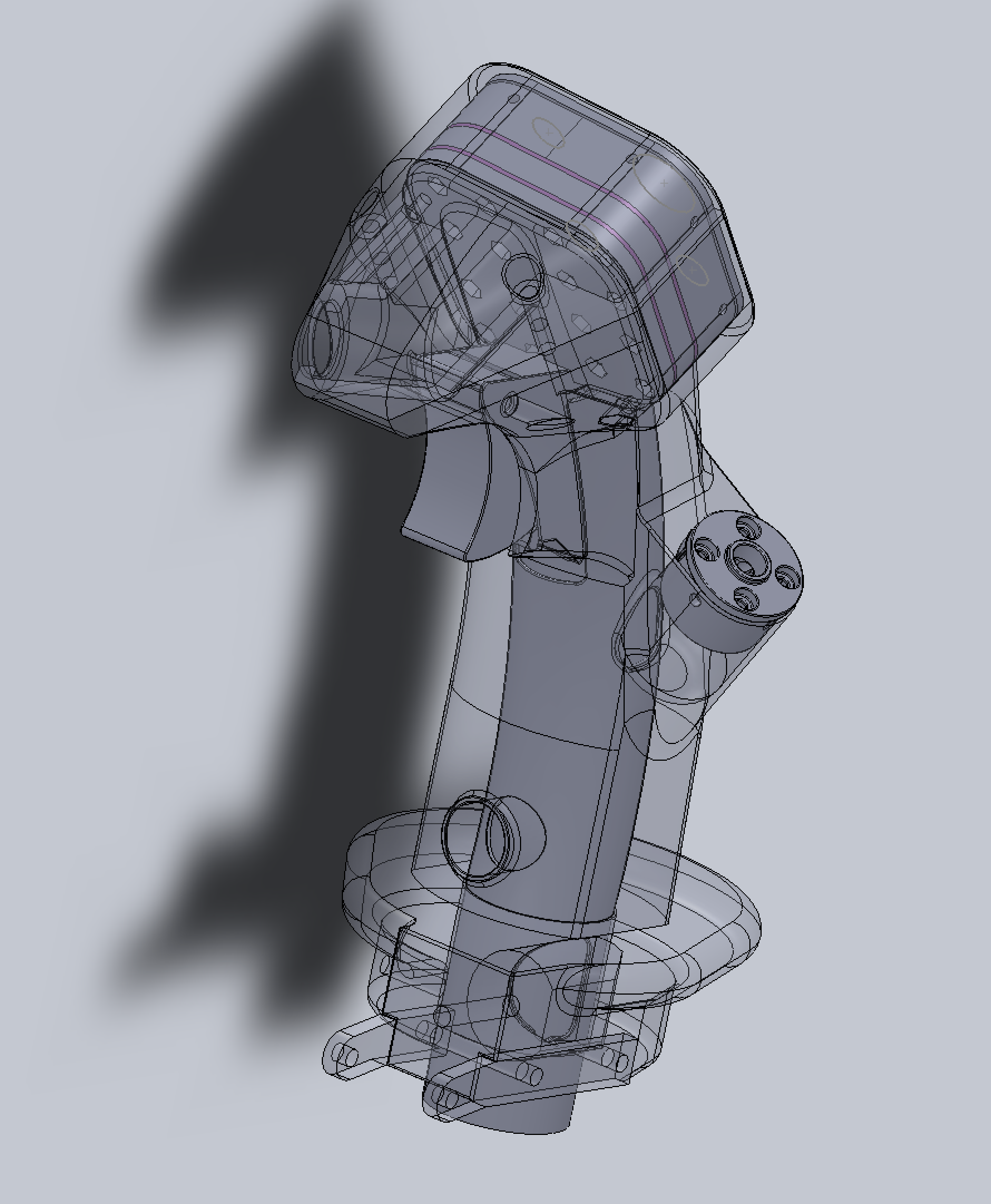
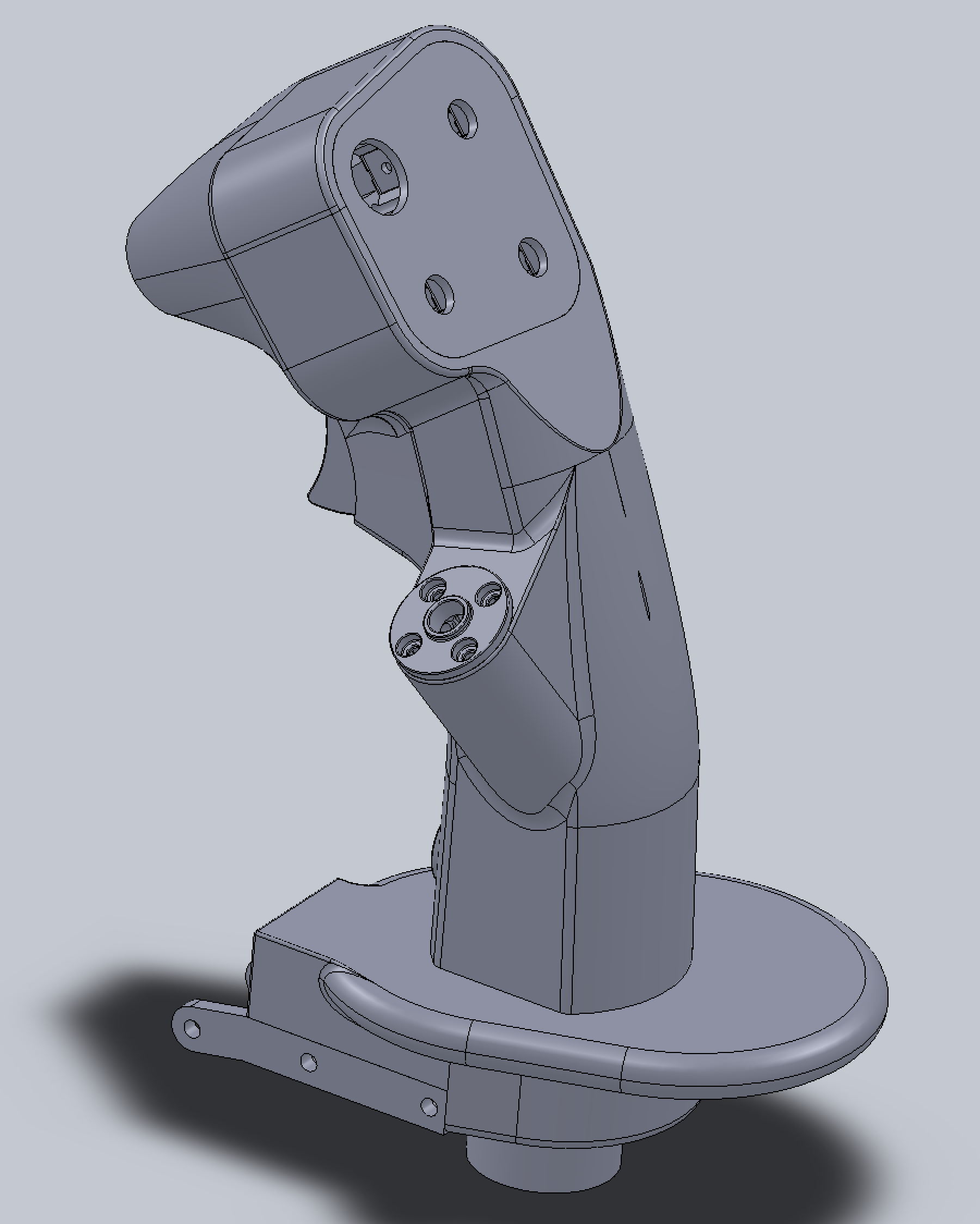
Mystery part, the first screenshot. This is a part I have been working on for the control stick base for the past two weeks. Still have to print the final revision and test it. After this, I will have to resolve the wire routing problem, the details. Actually, you see the three circular slits cut into the rings, one obscured in screenshot? Those are slits intended for routing sensor wires, all 29 of them. That means I have to design a magnet holder with wiring arrangement to go around the magnet, and a sensor holder to avoid chaffing the wires. The easiest solution is to route the wires outside (drill a hole in the stainless steel tube, insert a grommet, drill a hole in the base print, and run the wires with enough slack through it... done). But that feels like cheating. Not that I am against cheating here. I reserve the rights to use the cheat method here.... if my internal routing design does not go well. So, it will definitely work... it's just that I am pursuing something better. The 2nd screenshot is the OD=3/4" shaft vs. the OD=1/2" shaft. The OD=1/2" allows about 25 degree tilting each direction vs the 18 degree of the 3/4" shaft. With high enough resolution of Hall sensor, the decrease in tilting range should not be a problem. But actually might be an advantage, as it is closer to force sensor stick's small range. The increase in the shaft diameter is mainly to facilitate the mechanism for restoring linear curve, and 2ndarily this "wire routing" problem, wiring 29 of them through the OD=1/2", ID< 1/2" tube that moves around and have to avoid the sensor at the center is kind of a lot of troubles.

-
Tensioner block prototyped. There are always a lot of these "supposed" to work, or I will figure out something, during the draft design that are not taken to the very last details. Every single one of these have to be actually resolved and prototyped. There are a lot of these "need" to be prototyped. A lot of those problems are unforeseen. I have always wondered how there are people who can design it one pass and everything worked. nullAlso, since now I cut the main body into three to solve the "support removal", and cracking problem, now I might have an opportunity to integrate the tensioning blocks as part of the main bodies. That is, forget those two M3 screws and nuts you see in the picture. The block will be part of the main body, and just leave a slot for the middle nuts to slide in. But this is structurally weaker than with the two stainless steel M3 screws as reinforcement... blah blah blah.... Not much of the advantages with integrated tensioning blocks, other than a shorter BOM. BTW, I have another idea about how to mechanically restore linear response curve, a much simpler mechanism than the previous one, but should be as effective. Definitely will need to prototype it.... and patent it. So, you won't be seeing the innards of this thing than what you have already seen. This also greatly influence how the wiring will be routed. Also, I don't have an anti-torque mechanism yet. But I do have a rough idea how that will be accomplished -- outside, so it can accommodate the desire to rotate the stick any angle you see fit (within limit, say 30 degree left and right). It's so simple that you probably will laugh your tail off when you see it. I have not made the decision on whether I want to take advantages of this and route the wires through it (may not be practical). Like I said before, I think linear response curve is overrated. But if I can provide a simple mechanism to restore it, as an option, then I am glad to do it. But I myself am probably gonna go commando without it. However, prototyping is still required.
-
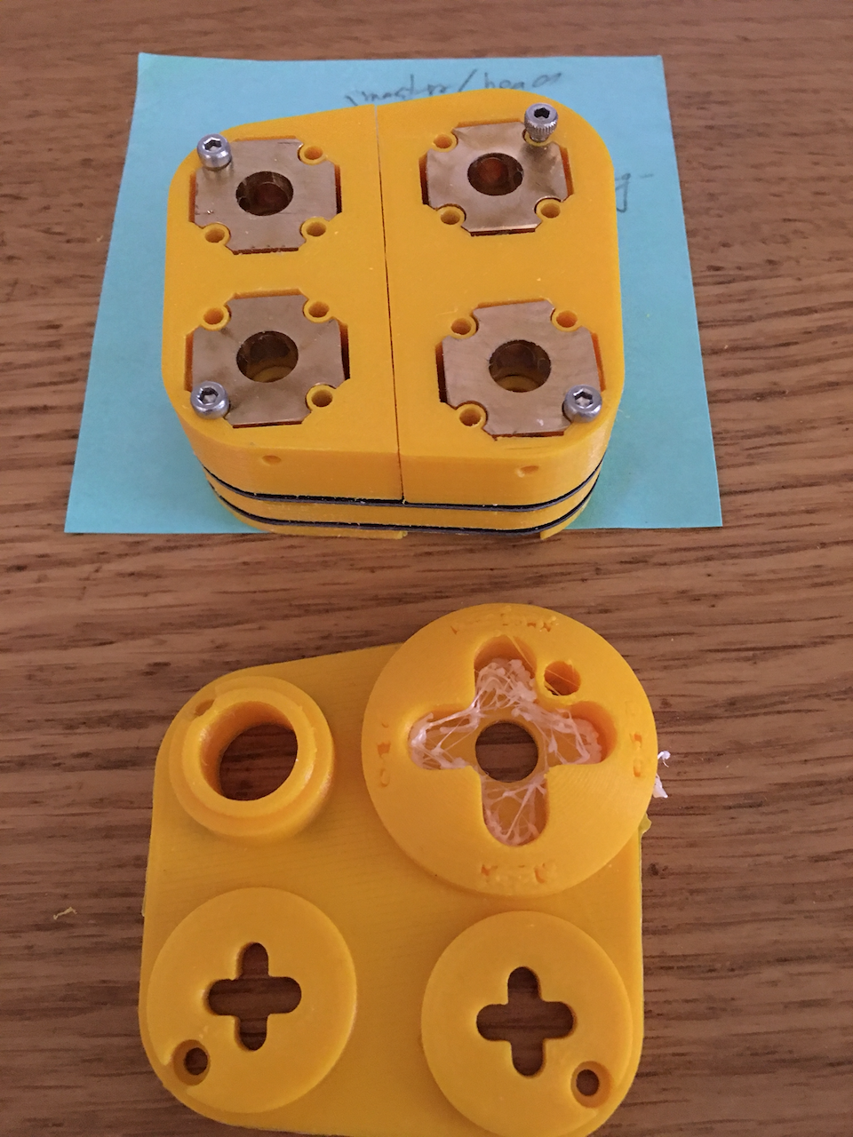
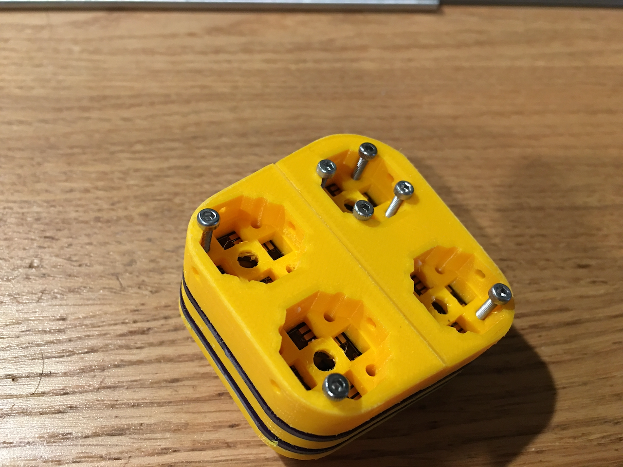
Received the thinner F16-like stick main PCB. The whole electronics stack is assembled (a new modification is made to prevent screws from contacting the brass optical core and short out the signal lines. The integrated main control face plate is printed on a 0.4mm nozzle with PLA. As expected, the whole thing prints out fine, but the engraved text does not. Either this has to be printed with a resin printer (or SLS), or this has to be printed without the text. Note that, these 4x optical cores are newly CNC milled. The "holes" for the screws are bigger to accommodate the printed "insulation sleeves" around the screws to avoid shorts (I forgot brass is conductive when I switched from disparate brass tubes to one integrated block; oops). Also, I now need to find a way to reliably contact the PCB screw pads and the screws (I think I have a good idea how). Because I found different batches of OshPark made PCB drilled the holes with different sizes. They used to be slightly undersized, but now they are slightly oversized. Well.... nature of oursourcing.
-
Received laser cut stainless parts from OshCut. nullI already know one part needs modification. I am changing the shaft OD from 1/2" to 3/4". So, the disk in the front need to have ID=3/4". Maybe my D=3/4" HSS annular cutters will be able to cut it at around 100 rpm. And now the disks with 3 prongs is slightly problematic; won't fit though the slits I cut for assembly.... damn it, just 0.5mm too big... argh! Need to go buy a 3/8 or 1/2" drill mill to make those 3 slits to be 3/8" or 1/2" wide instead of 1/4". Or I can just cheat and file the slit, just a notch to clear that 0.5mm. Gonna be ugly... but will work.
-
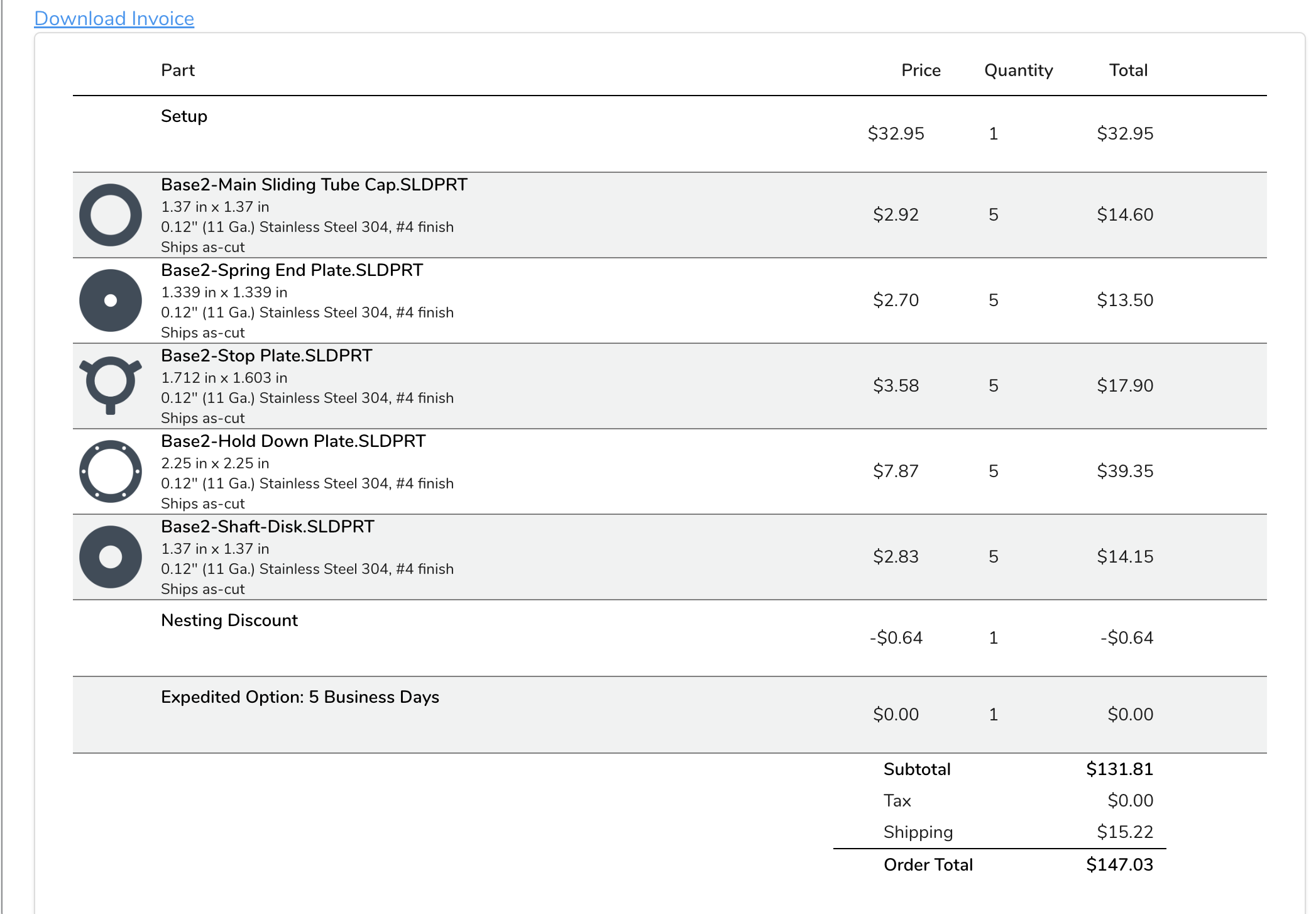
Laser cut for disk parts of the control base. 304 stainless steel (why not since I am going to spend the money laser cutting it! It's so pretty!). The parts themselves are not expensive, the setup fee is about USD $33. I could make them myself (not with stainless... too difficult to cut by hand or even with a CNC mill, 10X slower than aluminum and have to use flood coolant.). For instance, the disk on the shaft disk, I cut it by hand out of a piece of mild steel bar stock, drilled a 1/2" hole, trim the corners with a bandsaw to save some lathe time, braze the stainless steel tube in, and then lathe. It's easy, but if you are making one of anything, the setup and jigs always cost you plenty of time! Same goes to Osh Cut. They charge some not unreasonable, but not cheap setup fee too. The easiest way is to upload it and let them do most of the works. You can do it all by your lonesome with a scroll saw (not with 304 though, it would take forever and eat up a lot of your saw blades). It will take about 8 days for them to cut it and deliver it to me. Typical prototyping at home scenario... like in the Army -- hurry up and wait. Update: Ordered on Nov. 1. They said ship on or before Nov. 8th. But they actually shipped it out on Nov. 3rd. I am supposed to receive it on Sunday.
-
Made that shaft-disk thing on the right of the first picture this weekend. The shaft is made of stainless steel (OD=1/2"), plenty strong for the hair on fire animals out there. The disk was made of some hot rolled mild steel, cheap, brazed on the stainless, and then lathed. Brazing should be plenty strong enough... if not, I will pull out my TIG welder. Brazing is plenty easy for everybody. So, my first prototype is with this method. All you need is a MAPP gas torch, a roll of brazing "rods", and some flux. Additionally for alignment, I used a fire brick, drilled a 1/2" hole, and a recess of 3/4". This fixes the relationship between the shaft and the disk for brazing, and prevents the hot brazing liquid to come in contact with the brick. Perfect alignment is not really needed. A degree or two off is unperceetable to humans. So, I used a $99 drill press to drill that 1/2" hole (with a masonry bit) The up-down movement is not unlike TM Warthog, but I got rid of the ball and socket (I only realized it's similar to Warthog's after I got the solution). And everything else is different. The 4x "rods" mechanism in Warthog causes force dead center and sticktion. The ball and socket mechanism causes some sticktion. This mechanism has practically no dead center, and no sticktion. The response curve is not linear. But I have a very clever more complicated mechanism for linear response curve, which I do not think necessary, and I might want to patent it anyway. So, the prototype will only have that non-linear curve thing, but if necessary, I will curve it back with the firmware (compensated linear curve or uncompensated native non-linear curve). But, I highly doubt I will need to curve it back at the firmware. Of course, the end product will not have those M3 screws protruding out so far (3x more, total 6x, although 3x should suffice). I wish they were handsome socket head screws, but unfortunately, there is no socket head screws that long off the shelf. I could TIG weld them... There will also be a hopefully stainless steel ring on top of the red body to be screwed down (and cap it). Next weekend's works.
-
Probably a Really Basic USB Question, but...
Hempstead replied to Cavemanhead's topic in Home Cockpits
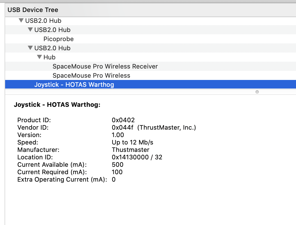
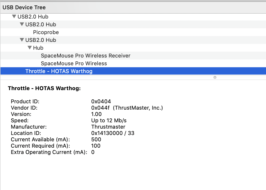
USB is designed to allow multi-tiered "hubs." If you plug into the USB ports on the mother board, those are usually the "root" hubs (not always, as some motherboard cheap out). Theoretically, you can plug in 128 devices into a single root hub (with many powered hubs), but not really recommended. Now, there is absolutely no requirement that your USB devices must be plugged into the root hub. Theoretically, a USB device can be plugged into any hub on any tier. BUT... TM Warhogs are known to be buggy when it comes to firmware update. If you don't plug it into the root hub, the firmware update may or may not work. Also, it will not work if you try to update the firmware when the Windows is a VM. I suppose, the fault really lies NOT with TM, but with the MCU manufacturer, ST-micro. With my USB firmware, Hempstick, I don't even know HOW to do what Warthog is doing... just can't do it, no matter what. Of course, I used Atmel chips, not ST. Also, I have found TM Warthogs bitchy when plugged into USB3 ports, particularly if your USB chipset is early Renesas USB3 chip set. I had to avoid that by buying an el'cheapo USB2 PCI-e card and a hub. Theoretically, USB3 is backward compatible with USB2 devices, but ST-micro's chips TM uses in Warthog predates USB3 protocol, so there wasn't anyway for them to test against the future. It's not like your Warthog can take advantage of higher speed of USB3 anyway. And each USB2 port can only supply, legally 500mA max. So, no, without powered hubs, you can't plug in more than a few devices into the same unpowered hub. So, to plug in more than just once device, I'd recommend powered hub, because one device along could theoretically request the entire 500mA. What I would really recommend you do regarding setup in a flight sim is to buy a powered USB2 hub, either plug that into a USB root hub (a waste), or plug it into an upstream USB3 hub. The best is to plug it into a USB2 PCIe card. I would not recommend too many tiers. Because the USB traffics is after all handed down one tier at a time. Not too much time is wasted, but it's some time. Luckily, we usually don't have more than 2 tiers, max. 3. Completely negligible. null Here in the following two screenshots, you can see that both TM Warthog stick and throttle requires some moderate 100mA, not exactly some high powered devices. But, the thing is unless you inspect each USB devices, each could theoretically request up to 500mA. So, it's easiest to just always buy powered hubs. The only reason I buy unpowered hub is for laptop portability. But if you have to plug in more than 1 device thus requiring a hub, it ain't that portable anymore, right? So, yes, there are cases for unpowered hubs, but not for flight sims.
-
And remember, Viper stick is just a stick I am modeling and apply the optical switch on. It’s not the only thing the optical HAT/button can be used in. Although I mainly fly the Viper in DCS. I do fly other stuff that are not Viper, like the Extra 300. Not everything has a mechanical delay of Gatling guns!
-
Mainly on the axis, to get more responsive and precise control. You might not be able to react quick enough from seeing one frame and effect an input before next frame, you can certainly see the trend and move your hand in a “rate” to get multiple inputs in between frames. Now once that is solved, you want to couple it with crappy button responses? 20 ms is a long time in computer signal delay. You never start pressing the button when you see the piper on the bandit, you time the button press to take effect when the piper will be on the bandit in the future. That won’t work well if you can only have a button input every 3 frames on display. Plus, we are only talking about latencies inside the controller. We have not accounted the time it takes for the report to be transported via USB bus, and bus collision avoidance time, host OS interrupt response time or scheduler time, then travel up the host driver stack, and be picked up by the software’s event loop, calculated the response, waited for the discrete event simulator’s next time tick, and acted upon. Windows default scheduler has a tick rate at the magnitude of tens of ms, around 30ms. And you just added 20 ms on debounce time, just inside the controller. 20ms latency is quite substantial! When you are shooting a missile or a Gatling gun, it probably doesn’t matter, because there is always a mechanical delay. But if you are shooting a chain gun, it matters for the first round out (if the sim can simulate it). The goal is to have inside controller latency to be at least an order of magnitude below human reflection time. So it becomes insignificant to human reflect and default general purpose OS scheduler. Best athletes have been recorded to have about 100 to 80ms. Which means about 8ms., which turns out to be about 120Hz…. Not a random number.
-
Short answer, two words, latency and debounce. Long answer. Latency and debounce are kind of related. Here's the thing, when you close a switch, the mechanical contact will close, open, close, open several times. How many times and how long depends on the design/construction of the switch. For your wall AC switch, 20, 30 ms is not unusual. For your AC light bulb and many other applications, it's not a problem. But for computers, it's a huge problem. You don't want pressing a button and fire, sometimes 3 missiles, sometimes 4 missiles. Do you? Worse. In order to solve this problem. Standard solutions are mainly in two categories. 1. Hardware Debouncer, 2. Software Debouncer. Hardware debouncer are usually based on hysteresis circuits. So, to turn on, you need, say above 3.0V, but to turn off, you need to be below 1.5V. So, once you get above 3V, if it doesn't dip below 1.5V, it's still on, and vise versa. Software debouncers on the other hand does this... once you detected an on/off state change, wait.... come back and sample it again after some time, say, 20 ms later. If it's still on, report a state change. Otherwise, do nothing. This is the approach Hempstick took for TM stick (that PS2 connector on the stick), even though in the stick there is already a 3 chip cascaded buffer which kind of buffer the on/off state and kind of a debouncer. But for direct leads on the chips, Hempstick configures a hardware debouncer on chip for each lead. The trouble? Unless it's a built-in on-chip hardware debouncers, you would have to install hardware debouncers .... could get your circuit complicated. For buffer chip... like the TM stick, the debounce characteristics is unspecified. After all, they are designed and sold as buffer chips, not debouncers. Whether it's hardware or software, you get two problems. a). Different switches require different debouncer characteristics. Will your on-chip debouncers satisfy the OTTO switch you select? Probably not. They are most likely designed for debouncing mini-push buttons that kind of stuff commonly seen on PCB. b). Well... you have to wait for that period of time for the signal to settle. Either hardware waits for you automatically, or you wait with your software loop/interrupt. Either of that increases your latency. Time you press the button until the firmware report a value change. I calculated that for us simmers we need latency below 1/120Hz = about 8ms. That is we would prefer at least one control input per frame. Preferably more. By rule of thumb, you get an order of magnitude smaller. That is, 8ms / 10... the fastest you can get for Full Speed USB is 1ms. Close enough, 1kHz it is. Now, I will need to find some switches that has latency that is way below 1kHz. That means at least, 2kHz. Now, no mechanical switch I know can achieve that. Even if they do when new, wear and tear would kill it. So, basically there are two solutions... magnetic (Hall sensor), and optical. See why Razer went making their own key switches instead of using Cherry, and then developed those fantastic optical keys? Preferably, it has a built in amplifier that already conditions the signal so I don't have to expend valuable PCB space for the amps or DSP. It also has to be small enough that I can squeeze in at least 4x sensors in a can with OD=0.75", and still have space for tactile feedback mechanism that can be in sync with the signal. Click, and on/off state change every time. Hence, the 3 years of many different solutions to solve this particular tactile feedback in sync with the optical interruption. The optical sensor I selected has latency of about 5 to 20 µs. There is also a Hall Mini Stick... I started that project long before the 8-way optical switch. But got stuck on the pushbutton. So, I put it down and started the 8-way optical in hope that I can solve the pushbutton problem and reuse it in the mini-Hall stick.
-
Opps, typo king!
-
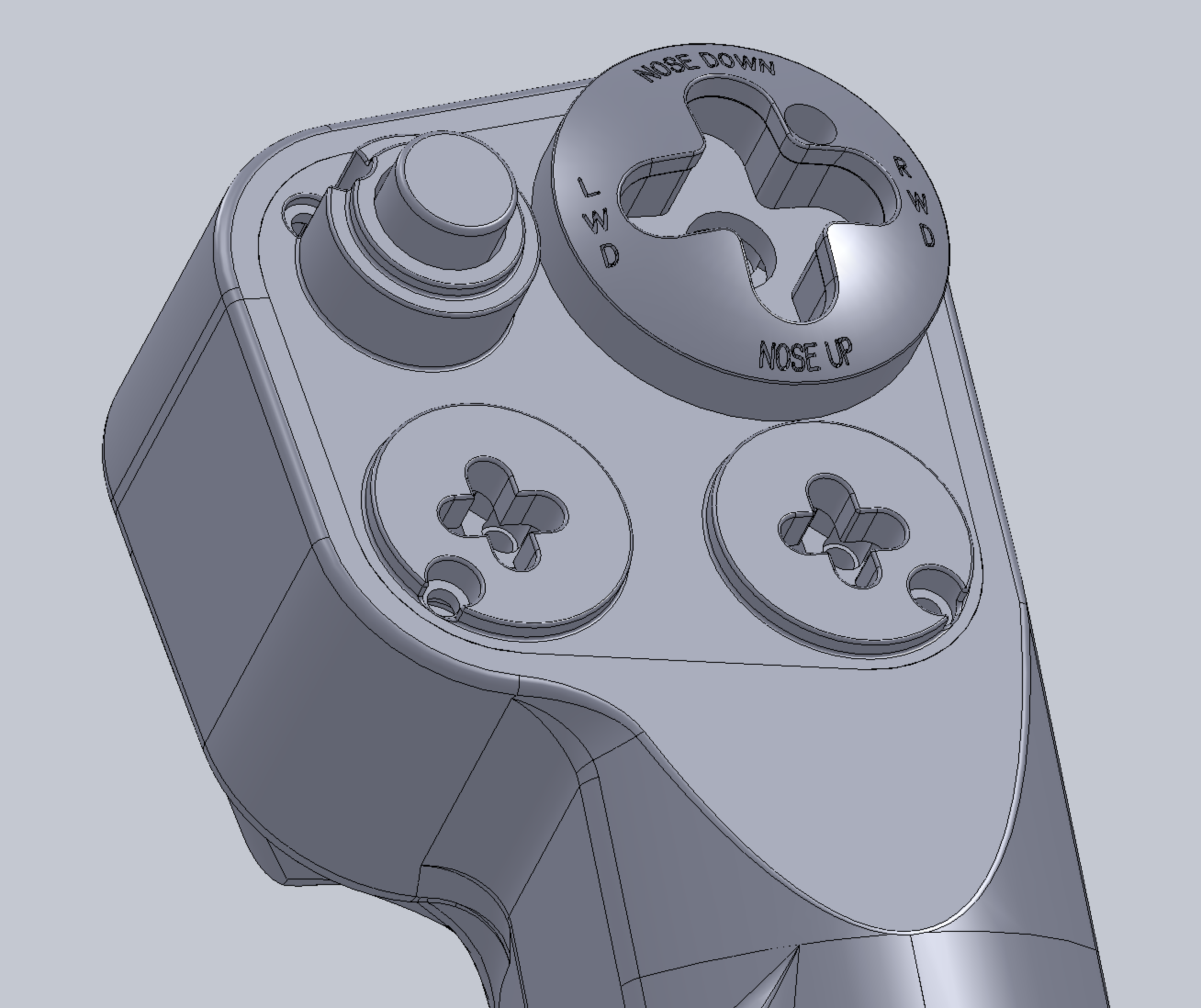
4-way now. The deal is that the shaft of each of the optical "8-way" is an OD=1/8" (or 3mm) stainless steel rod (solid). You just design a cross shape cutout and you got a 4-way. Here, the Trim, TMS, and DMS, and CMS all have +1. The +1 push buttons are configured with 900g trip force stainless steel dome switches. That's almost 1 kgf! It's very unlikely you will trip it unintentionally. It gives a very satisfying click. 0.9 kgf is still not quite to the level of force the OTTO ones have, but remember, we could fire hundreds of missiles a weekend. You don't want to get blisters. So, all of the HATs will have the +1 even though the original does not.
-
For the fun of it... populated some of the button "caps." This finishes the Main Control Plate by merging some of the button "bases" with the plate. For instance, now the trim cap base (the part with the text) is merged and is part of the main control plate.
-
10 years from now, we will probably be able to print this stuff at reasonable prices. 10 years ago, I spend $3,500 on a SLA printer, and it was pretty much a complete write off. Now, you can have one that actually works well for about $250. Fingers crossed.
-
Huh.... USD $788.94 for a 316L stainless steel print. If I go cast this in bronze... like I did with the TQS I will have to charge you about that range too AT LEAST (tons of labor and high failure rate), and it's basically chagring by minimum wage hourly rate + material and equipment costs, not making much profits. See why I am exploring plastic core fiber sleeve method? nullHow much would the military pay for an F-16 aluminum stick body? $1,332.61 (let's say $2,000 for the whole thing) is not bad, if you know many hours I put in making those 4 TQS bronze castings (and I only have one finished)! And, I expect there will be very little sanding/grinding/polishing works with 3D printed parts, compared with raw castings. Me? Poor me is going back to plastic.
-
So, you are advocating a linear curve for all cases, if I understand correctly? Could it he possible that you curved it badly, causing human induced oscillation, thus removing that curve made it easier for you? I would very much agree that our setups and preferences are all different. What works for me not necessarily will work for you. What I “reasoned” was that if your setup does not have “enough” resolution at the throttle range around 309 kts when the refueling door was opened, you are going to have trouble with human induced oscillation. That is often, but not always the cause of difficulty in AAR (to me, the biggest trouble was the inability to see the tanker indicator lights with my Quest 2, which I could see clearly in 4K pancake, so I am always guessing about my location). The main takeaway should be — if you have difficulty with AAR, see if you have trouble with fine adjustment of speed around 309 kts. If you cannot easily adjust within ±1 kt, then you need to try a curve to allocate more resolution to that mid-range throttle movement. Before ED updated the response curve when the refueling door was opened, about 2 or 3 months ago (?), it was nigh impossible for me to adjust within ±1 kt without a custom curve. But, if you are still having trouble with the ±1 kt trouble now. Try curve it, with a number to measure it with, instead of blindly apply some Internet witch brew. Not that Internet witch brews don’t work. If you apply enough of them, hopefully in isolation, one of them is bound to work. Witch brews? Yep, the ones come without reasoning. Moreover, if you want AB detent mod, you have no choice but to curve it. And BTW, a linear line is a special case of curve. I should say, a dog leg for the AB detent, then a linear “curve.” This gives me an idea of a mechanical adjustable throttle stop, in conjunction with my electronically programmable force generator! THANKS!
-
Like I said, my curve is useless for you, b/c mine is a Warthog. But the basic idea is that you want to reserve more resolution (movement of the throttle) to the mid-range movement right before the AB detent. Because this is where your throttle will be for fine tuning your speed to match up to the usual 309 kt/hr of the tanker. You will need enough resolution to fine tune your speed within 1 or 2 kts. If your default linear curve can't fine tune within 2 kts around 309 kts.... you are going to have a very short window of staying in "contact" with the fuel probe. Staying in sync with the tanker will be very difficult if you can't stay within 307 and 311, preferably within 308 and 310 range. I am able to make it stick to 309 for something like 15 seconds, and the I would slowing either go forward of drop backward... as soon as that happens, I adjust for one more kt, 307 or 310 to get back to the middle. You see, if your throttle can't fine tune to that resolution, you are bound to be doing 315, or 305 and nothing in between, so your window of contact could be as short as 3 seconds... so every 2 seconds you will be doing a human induced oscillation. You come in with 315... contact... and you reduce the throttle a bit... 2 seconds later, you are dropping back too much... so you bump up the throttle a bit, and 2 seconds later you are speeding at 312... so you reduce a bit, and so on and so forth. And in the mean time you are dealing with human induced speed oscillation, you are drifting left and right, up and down.... And again, if you are not curving your stick to your liking, now you have 3 human induced oscillations to deal with simultaneously.... I don't know about yours, but my brain can't compute that! Sure, once you opened your refueling door, the response curve changes, DCS models that, and that helps a lot, but if your throttle and stick are not able to provide enough resolution at where it counts, 309 kts... it's difficult.
-
Nah... I cleaned it out once. And it kept coming, so I didn't. It's been over 10 years. I am still good. The deal is that the main sensors are MLX90333 in digital mode. Not sure about the later model, but I doubt they would change it, because the digital mode requires a "non-standard" 3-wire SPI wiring. Changing to say the later all digital MLX90363 will require PCB change, b/c this baby uses a standard 4-wire SPI. Since they are Hall sensors, unless the shavings get into the axel or the pot in the white friction to the right of the throttle, other switches and buttons are pretty much sealed.
-
The shaving is totally normal. One of mine has been in service since Warthog’s release. The MIC switch had been torn down and cleaned up several times, and finally the whole switch assembly replaced. And the throttle with all the shavings is still ok. Just don’t keep tightening the friction wheel to get higher friction. When it reached equilibrium, leave it be. I mean, you don’t want more shavings, right? Let’s just say the friction is not adjustable, unless you have a lot of consumable pads; it’s a design fail.
-
I don’t have a VKB, but I use Warthog with the stock very strong spring. My recommendation — you need a curve for the fine adjustment of the throttle. Believe it or not, aerial refueling, and ILS landing (if you are aiming for proper glide slope tracking w/ little to no stick works) are a lot of fine throttle works.Those are not the hair on fire maverick kind of jobs. I couldn’t do F-16 aerial refueling before I did a curve on my throttle, and stick. But, after the curves…. still a lot of practices, but I could immediately see the end of the tunnel.
-
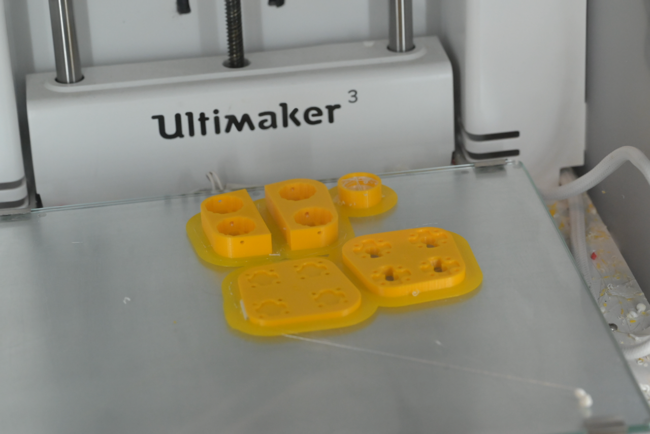
I usually use the trusty Ultimaker 3 first for test fit. It's always there. Sure, it takes much longer to print than my fleet of Phrozen resin printers (Mini 8K, Mighty 4K, Mighty 8K, and Mega 8K), but no post processing and all that to deal with. nullnullnullnullnullnullThe 7 screws in there proves the alignment is good.
-
Note that, in the electronics assembly, there is about estimated 1.5W power consumption. I have no idea what this would do to the tightly packed without any air circulation assembly. I would say, probably not very good. I am printing the plates of the assembly for fitting prototype while I wait for OshPark's new PCBs. I will be cutting some fancy "channels/patterns" for air circulation/heat dissipation; if not for anything, for the looks nobody will see!
-
The main modeling work of the stick design is pretty much complete. The main control face plate has no cutout. This is up to you to decide what you want to have, and solder the sensors in there accordingly. Now that the face place is considered part of the electronic assembly, it will be fastened to the electronic assembly with 4 M2 screws, 2 of which extends all the way into the main body for fastening to the main stick body. They kind of stick out of the face by about 0.5mm.... I kind of like it. The top cover is screwed down by two M3 screws into the main body. I only modeled the recess for screw head and the M3 holes. But, this is intended to have 3D print screw brass inserts. I would prefer to have 4 or at least 3 screws, but there is just no "meat" for them. Two will do just fine. What're to be done are basically the LOOOONG process of customization for myself and prototyping it. No, I don't release things without prototyping. I have learned from decades of experiences that I am just not good enough to consider every little things without the repeated design-prototype-modify-prototype-modify... process, unlike some genius who could do it in one go without prototypes. I am waiting for my OshPark PCB, the thinner 0.8mm version. The regular ones I have, 1.6mm, is a bit too thick. The electronic assembly collides with the OTTO trigger. I chose the solution of buying the thinner PCB. There is still collision. I cut the back plate of the electronic assembly for it. But, most likely I will design my own trigger with optical sensors. I just "solve" the problem in case somebody wants to use OTTO trigger (very satisfying click). The optical sensors are not cheap... USD $3 to $4 a pop depending on how many you buy in one shot. I count 30 sensors fully populated. These alone would cost about USD $90 to $120 + tax + s/h. And since there are 30 signal lines... That will need two RPi Picos. No, no matrix circuits nor buffer chips. I am going for low latency. The optical sensors not only have no electric bounce, their latency are about 8 to 20 µs, L-H and H-L respectively. TODO: Print the damned thing (waiting for Phrozen's pre-order Onxy plus resin). Assembly prototype print will probably be printed in 2 halves on my Ultimaker 3. As with many of my 3D designs, NozzleDiameter is a property that you can change. Say, 0.4mm for Ultimaker3, and 0.1mm for Phrozen Mighty 8K (0.05 will do, but that's quite meaningless). So, for different printers, I can just open the file, change the NozzleDiameter, regenerate the STL file, and slice away. Adaptor to connect to the no-gimbal box. The electronics assembly prototype. Fitting of the optical 8 on CMS "hole." Design just the buttons (kind of already have it) for the NWS button and the two pinky buttons. Waiting for the D=2.5" Kevlar sleeves shipment. 2" is just too much forcing it. Then, do the vacuum thing. Write the Hemptick Pico. null null
-
Much better improvement, theoretically, on the CMS "wire hole" cutout on the inner tube, much smaller. And re-enforced the root of the "CMS bump." And, import the optical sensor cap v.11 as the CMS. Most likely, I will just use a longer M2 screws making it extend into the bottom of the CMS "well", and put a nut from inside (this is going to be tricky to put in but not impossible, and will have to be very carefully shield when epoxying the inner tube in.).