Hempstead
-
Posts
473 -
Joined
-
Last visited
Content Type
Profiles
Forums
Events
Everything posted by Hempstead
-
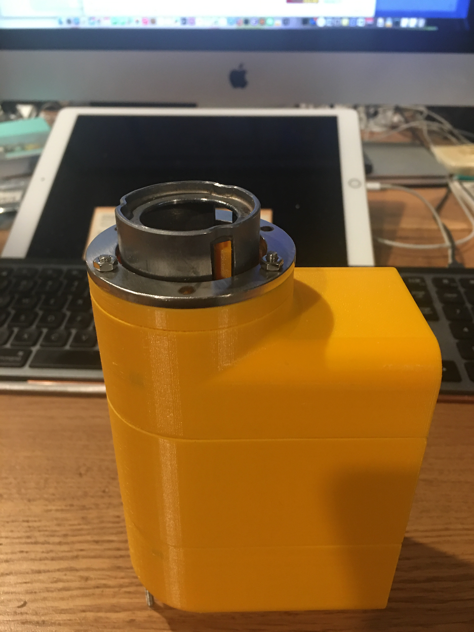
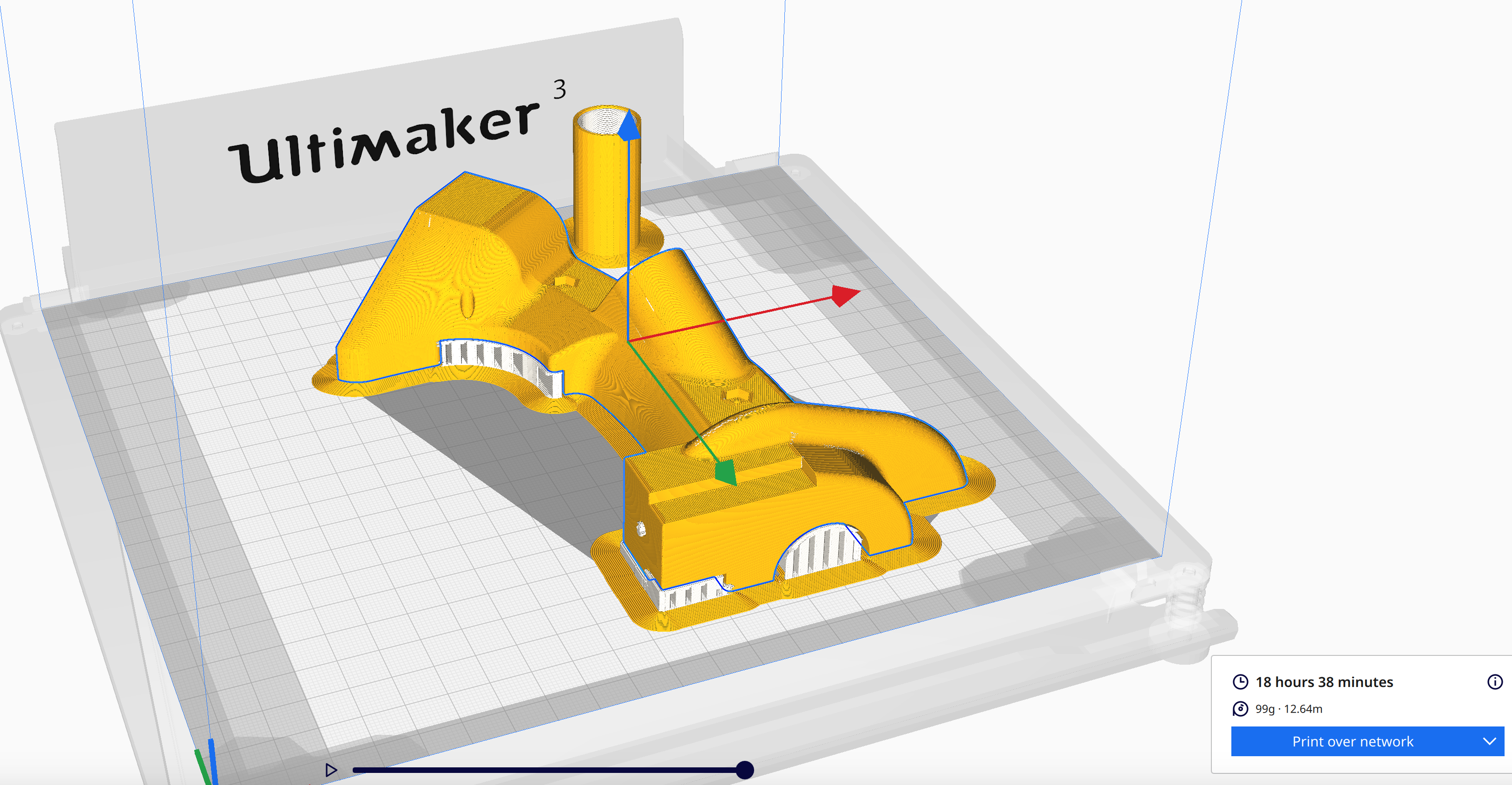
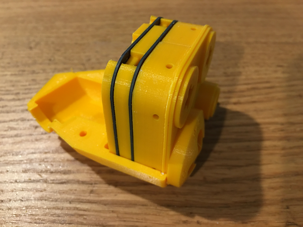
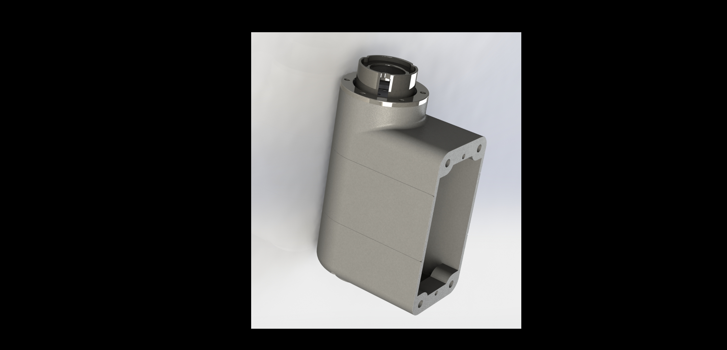
I have been working on the stick base 2's sliding mechanism prototype... time consuming... because I had to adjust the depth of bearing seats.... by experiments (the CAD calculation... using geometry to constraint it didn't work quite well; Call me old school... I was trained in drafting class, yes, with pencils, to use construction lines to constraint my final constructs.). That is... print it... test it, adjust, print, test... Luckily, I can just slice up to only a section of 0.5" high ring for the body and print just that to test. Still each section takes about 4 hours to print... That alone consumed the past few days, ran through one spool of PLA filament. Now... Tada! It works beautifully as I expected. This is the design that allows zero dead center, no sticktion (practically). It's inspired by TM Warthog's these two problems. That is... I set out to solve these two problem, and several years later, I proved I solved the problems! Now I have to solve the 25 wires routing problem and the anti-torque problem. Currently, I am inclined for an external solution. Yes... I had reserved some space for the wires to to through internally, but it's very little space. it's a ring shape of space of only 1 mm to 1.5 mm wide. I could get it through with 30 gauge wires, but what I worry about is the still-to-be-patented linear curve restoration mechanism will have moving part around that ring space for wires.... that could cause pinching and chaffing.... Oh, no... not on F-16! Some cosmic poetic justice thing? It's uglier to have external solutions.... but maybe, just maybe I can make it not so u.g.l.y. BTW the main body in the picture is split into 4 pieces... it could be two... but I split it into 3. The top piece that ring under the stainless steel was a printing mistake... the filament got stuck so that piece wasn't printed correctly. I just slice that part up and print it. That's one of the great things about switching to the 3 to 6 long screws to assemble the main body, I am free to split the main body to any # of piece >= 2. 3 is great because 1. it split along the original aluminum cover lines, and 2. it makes assembling the bearing and bearing tensioning blocks a whole lot easier than unibody. (think if it were a unibody... the main sliding tube has no choice but to go in from the top... and what about the bearings and tensioning blocks that are deep inside that main cavity... very tricky to assemble!). Also, the mechanism does not have to be this long (the main tube is about 4.5" long). But the longer the better... i.e. the long it is... the less dead center, which is the problem with TM Warthog, the center "piston" spring platform has to tilt slightly to avoid the corners of the 4x steel rods from binding, about 1" long. My design won't bind because I use ball bearings to solve this binding problem. But still, the shorter it is, the more "physical slack" due to manufacturing/tuning imprecision will be amplified. My "guess" is that it has to be at least 2" long, if not 2.5". My original design was indeed 2.5" long. But one day, it hit me... why don't I just stick this thing into an F-16 stick base, which I already have a 3D model? Ok... make it as long as that thing would take! 4.5" it is.

-

Any Quest 2 gurus out there? Can't get DCS to run.
Hempstead replied to Maolain's topic in Virtual Reality
No problem…. We all forgot to plug in the power once or twice. Since you are new… the other thing DCS is really “surprising” to new comers is that it will detect all the analog axes for all the controllers you plug in and assign the roll pitch yaw to all of them…. Yes… yaw will have multiple analog axes from multiple controllers assigned to it. Same goes to pitch and roll. So, you “might” have to clear all of them out, manually and then assign just one you want. Otherwise, you might get into situation where you pull on your P51, and it also roll left violently and crash, or sone weird input coming out of nowhere, The kicker is… if you plug in any new controller in the future, it will be detected, and its analog axes assigned to roll pitch yaw again, for all your planes. Hence, you will have to clear that new controller’s analog axes again….. for all your planes. -
Any Quest 2 gurus out there? Can't get DCS to run.
Hempstead replied to Maolain's topic in Virtual Reality
I am assuming that you have "Allowed access to Data", and activated the Quest Link. And you are launching DCS from the 2D Desktop in VR from your description. First, make sure you have in the Oculus software on desk, go to [Settings] (on the left pane) -> [General] -> Check [Unknown Sources] Second, in the DCS [Settings] -> [VR] tab, make sure you have VR turned on. -
A slip of a fat finger... made the socket head screw size M2 instead of M3... oh well... nothing a little drilling and a 1/4" end mill on a drill press couldn't fix. Fixed in the model now. Trigger now works perfectly... no interference anymore. Just sand off the flashing and install. Don't have the right length M3 socket head stainless steel screws... Needs something like M3x0.5x34... odd length. I'd need to cut it down anyway... so I use some M3x0.5x50 I have at hand, and cut off/grind. One piece print will probably work fine. However, there will be two problems. 1. On an FDM printer, you get stronger body, you don't want to print this whole thing up right due to the weakness of the layers. If you print it horizontally, you get ugly underside... that will require a lot of sanding/filing works to restore. 2. Putting the center reinforcement aluminum main tube will be difficult. But, it's possible to slip in 1/2 of the tube only on the bottom halve (that's intentional... when I made that one curvature to two straight lines plus one constant radius... in case I want this option). But even if you choose this weaker option, you will need some way to fasten the tube to the main body. This usually means at least two screws, unless you are thinking about gluing. But splitting into two halves, I also needs two screws, and it's stronger than the "half measure." Other than the visible split line, I see all positives for splitting over unibody. So, I think the splits here is the best option -- left half, right half, and top cover. Makes it easy to install and assemble, and easy to make. Plus, if one day I decide to bronze or aluminum cast these... the existing two halves make it a breeze to make the wax pattern, pretty much as is with some minor fixes. Or... instead of using lost wax casting... I can actually do a lost PLA casting... (lost PLA works great, and all I have to do is to plug up the 4 screw holes and glue them together for investment).
-
null
-
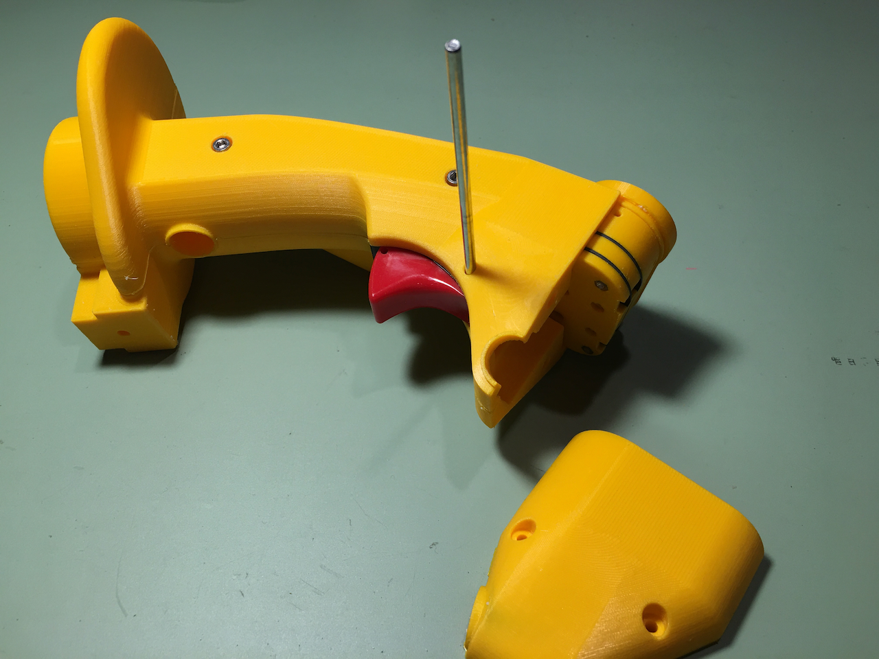
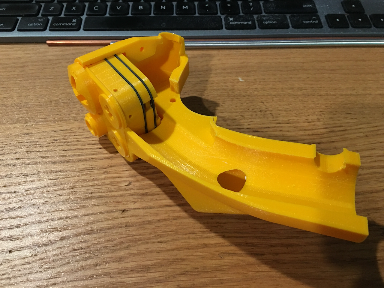
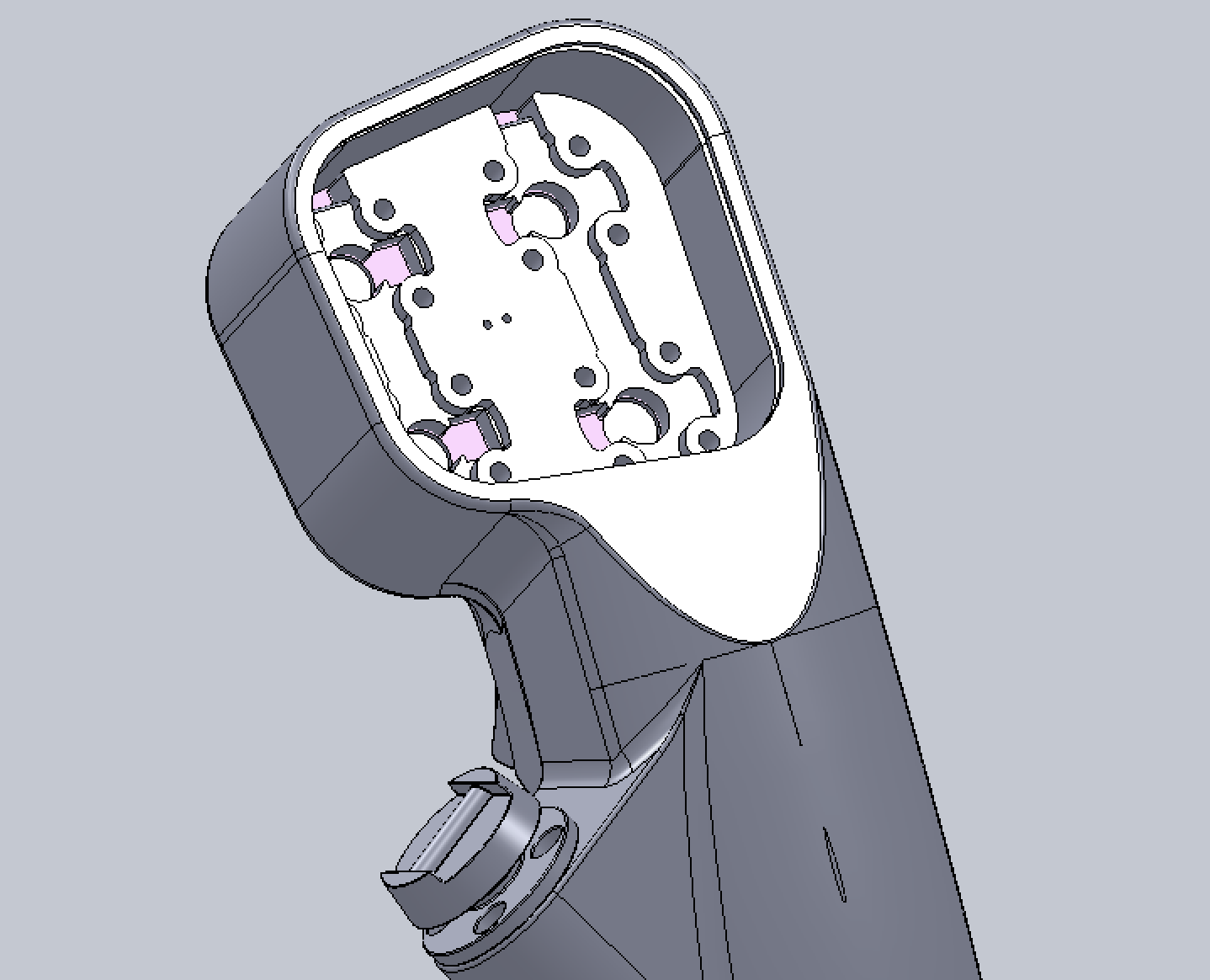
nullCorrected some of those aforementioned problems... split the palm rest in two, exported and the merged the main body.... both left hand sides of course. Why? Why not just merge then split, instead of split the palm rest, export to another file and then merged back? Simple... this last split of the palm rest is meant to be the last operation. So, if I ever regret it, I could still go back to the original idea of the main body is pretty much a straight tube with a bulge on top (no split), suitable for a woven Kevlar sleeve to encapsulate, and then epoxy and vacuum bagged. With that bulky irregular shape of the palm rest at the bottom the Kevlar sleeve would have trouble. Hence, the bottom of the main body is straight, and the palm rest could be slipped up and screwed down. Since the current experiment is to split the main stick into three pieces just like Warthog does and forego the Kevlar sleeve with just the plastic 3D printed body with an OD=1" aluminum tube inside to reinforce, there is no reason for me to still have that separate palm rest piece... BTW, I am printing with PLA... the easiest to print, and it seems to be plenty strong enough. I can assure you that after sanding/filing, Smooth-On XTC-3D, and more sanding, PLA could be actually quite beautify and smooth. Moreover, after priming and painting, you wouldn't be able to tell anyway.
-
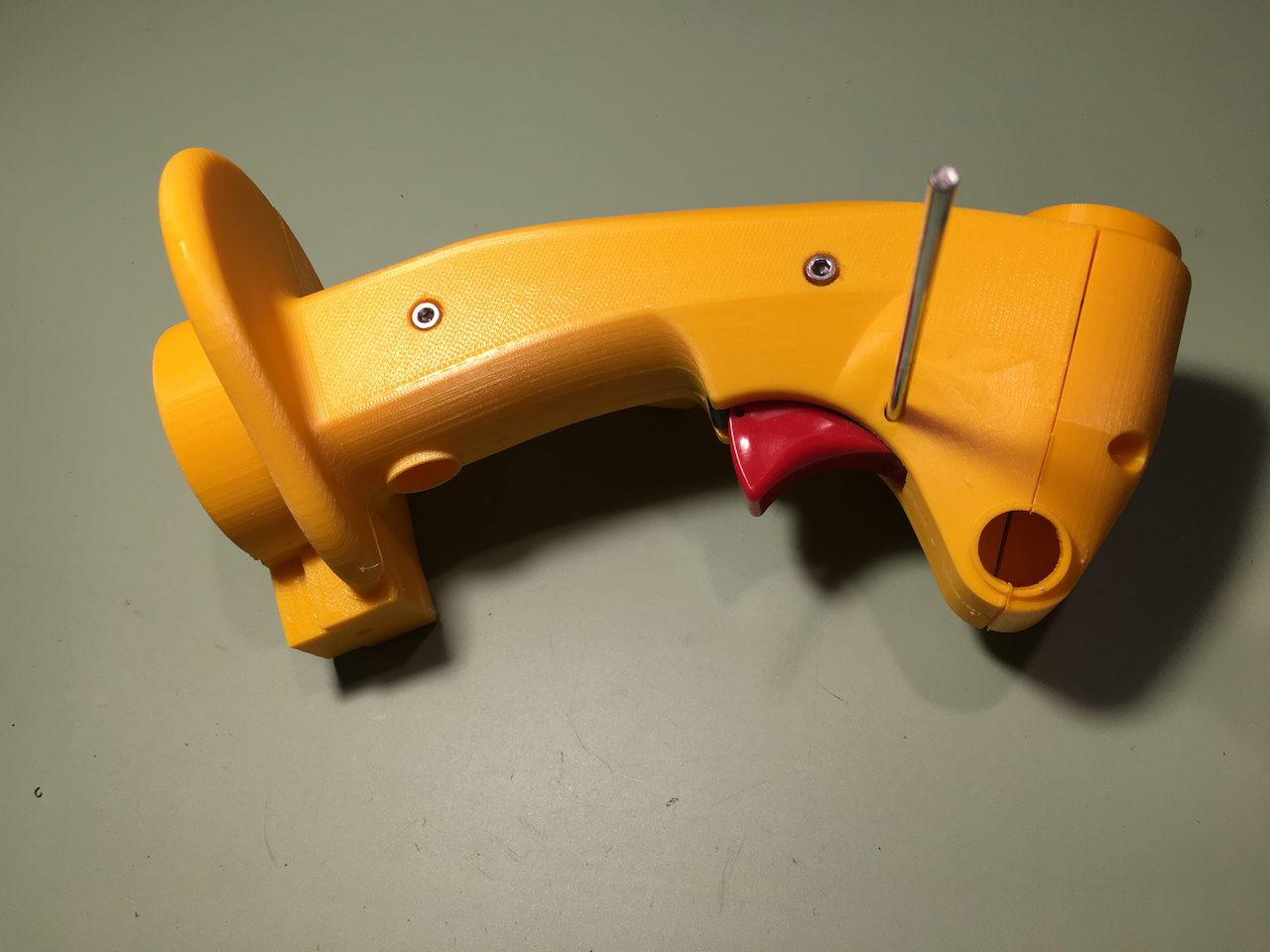
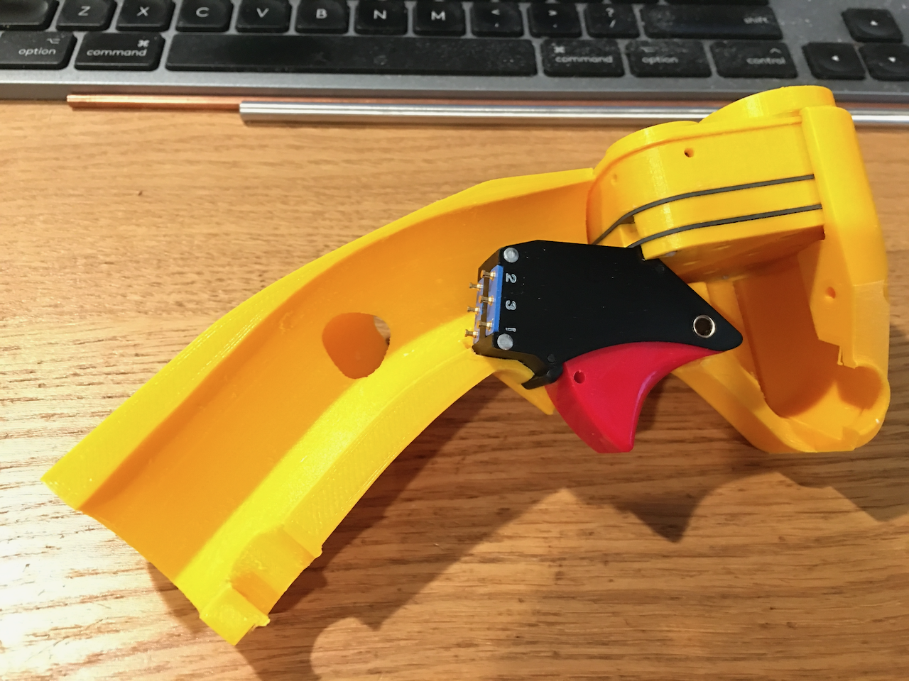
Needs a few minor adjustments, a little filing and sanding to get them to fit, mainly the tigger opening obstructed a little bit of the trigger movement. Also, the opening for the mil spec. genuine trigger is slightly too narrow (didn't quite account for the filament thickness...). A little sanding makes it fit perfectly, but I will adjust the 3D mode for these. The whole thing feels quite solid in my hand... not entirely sure if I would need the Kevlar-epoxy outer layer. I mean, it would probably stand by itself... and I also have an inner aluminum main tube for reinforcement... The outer Kevlar-epoxy layer would seem a bit over the top. If that's the case, then there is no reason to split off the palm rest off, since I am already splitting the main body into two for easy installation of the main tube. Might as well integrate the palm rest with the main tube, just like Cougar and Warthog, and then bolt the two halves together with some socket head M3 screws. Also, found there is not much space between the head, the main tube, and the trigger to run the wires... have to design some "spaces" for the wires to route through into the main tube. null
-
The whole stack test fit. No optical sensor soldered on yet. Because, they are expensive, and 16 of them! Not going to solder on until the whole thing is test fitted correctly. Moreover, likely I will have to file some slots in the PCBs for running wires (and cut out on the next revision of the PCB). null
-
I forgot to mention that the other reason for the abandonment of using stainless steel screws for signal paths is due to galvanic corrosion considerations. See, originally, the PCB is gold plated, so there is no problem between the stainless steel screws and gold. But now that the contact between the gold plated annular rings and stainless steel screws are found to be unreliable, I will have to design "something" to make that reliable contact. That "something" is most likely to be made of copper, and very likely to be simply a copper disk.... er... definitely not gold plated. So, now I either need aluminum/brass screws, or nickel/gold plated steel screws. Unfortunately, I have a hell of a time sourcing those. "They" seem to only make brass/aluminum screws up to M2x12. M2x21 to M2x25 nickel plated screws, I can only find one source in UK... and it's about USD $0.6 apiece plus about $25 shipping charge. In the 8-way optical HAT design, I have already considered this problem and had two different solutions for it. But I am not 100% happy with the two solutions either due to the space constraints in the 8-way. But this time, with the stick I actually have a lot more space than with the 8-way.... So, I stepped back, reevaluated, and ditched the stainless steel screws as signal path, and replaced them with nylon. It is still not easy to find at that length, but at least they are cheap and from an easy source, Newark/Element 14. You can still use stainless steel screws which would still make unreliable contact with the signal and act as a capacitor.... unnecessarily now that I have other copper paths for signals, although not adversely affect the signal too much. The side benefit of using Nylon screws is that I only have to buy one length... M2x25... and just snip it at whatever length I need. Stainless steel is a lot tougher.... consuming a lot of saw blades trimming them.
-
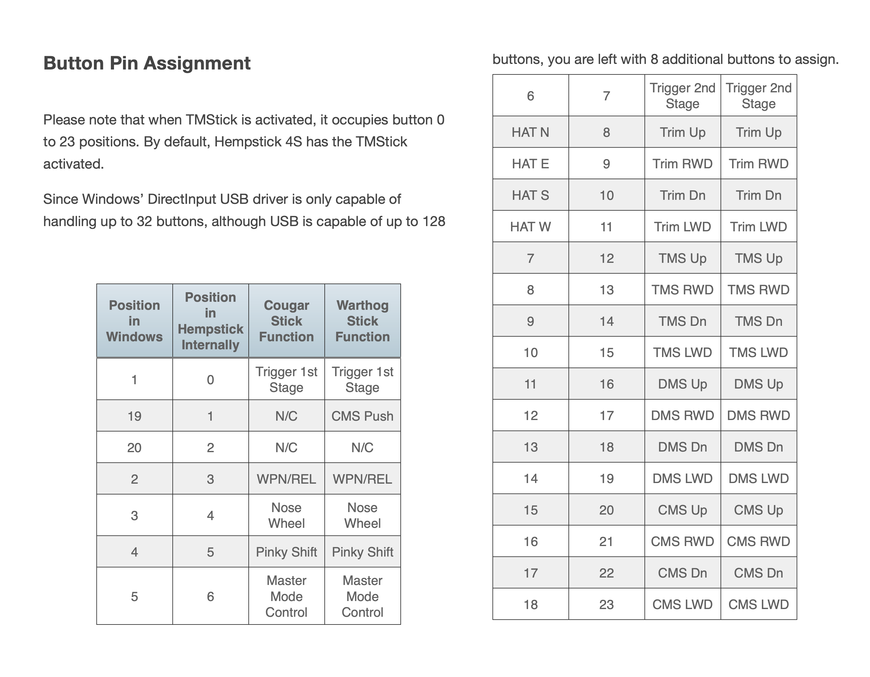
Simple... Take this entry as an example. J6P5 (23, 0) That means it's J6 socket on the board, pin 5, in your picture. Take '0' and look up into my table in the Position in Hempstick Internally. That gives you the Trigger 1st Stage from the Column Cougar Stick Function. Another example. J2P5 (7, 16) That means, J2 socket on the PCB, pin 5. Row 16 in my table gives you DMS Up for Cougar, meaning the DMS HAT switch up. If you have a Warthog, use the Warthog Stick Function column.
-
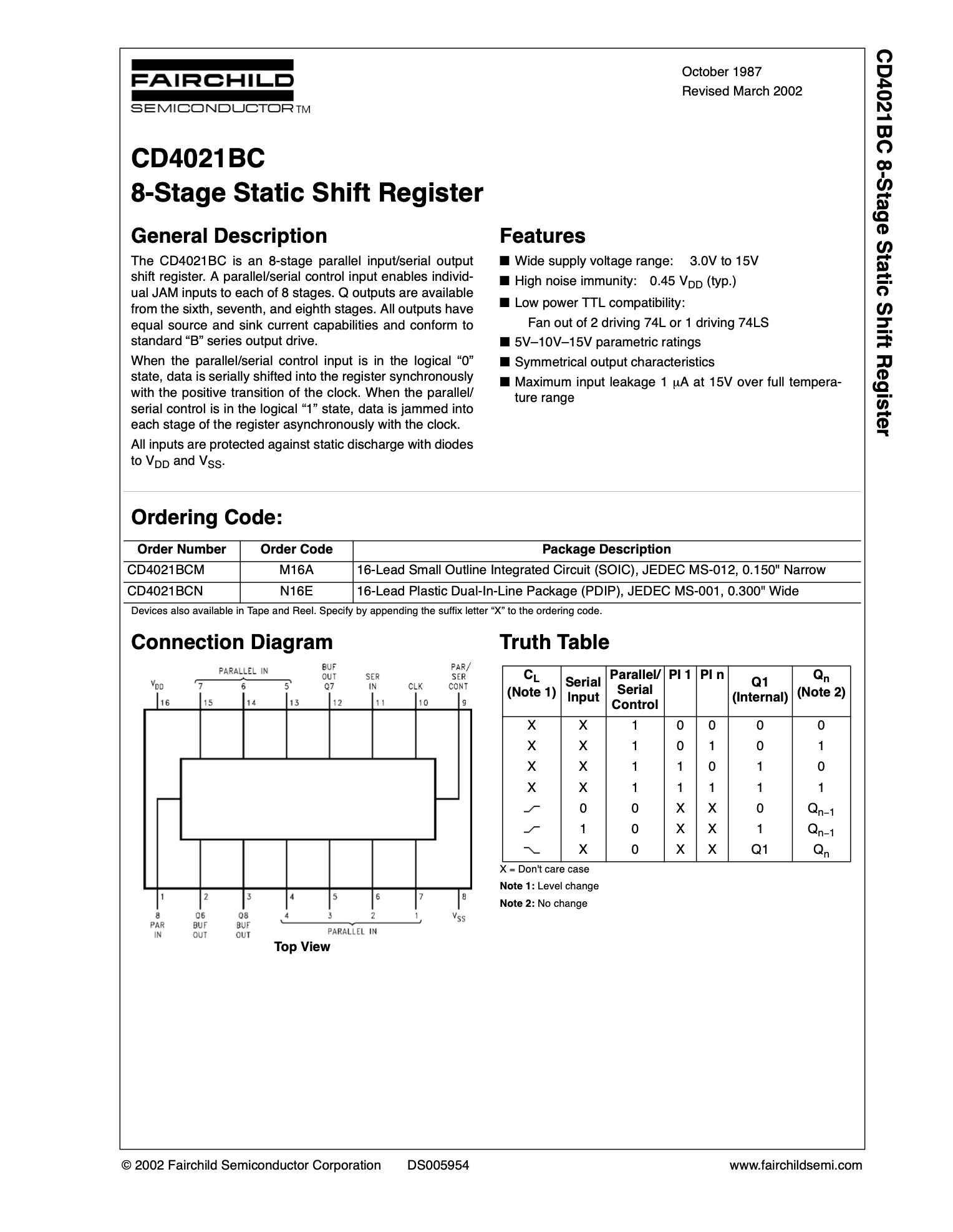
Here's how to decode them. 1. Look at the chip spec itself, see picture #1. There are the Parallel in pins, numbered 1 to 8. Bit #8 will go out first. That is, it's an MSB first scheme. So, 3 chips forms a chain of 24 bits parallel in, serials out. Normally, the values in the buffer changes according to the values on each lead... Whatever they are, the bits in the buffer changes with it. 2. When the Select pin goes active, 0V, the buffer locks up whatever values are in the buffers. Then, the caller sends in 24 pulses (clock), and each pulse sends out 1 bit of value. So, P8 on U1 will be send out as bit 0, etc. 3. In Hempstick User's Guide,http://www.hempstick.org/download/manual/Hempstick-UserGuide.pdf, I have listed all the values. For your convenience, I have included a screenshot in the 2nd picture. In that table, use the column Position in Hempstick Internal. I don't remember which end is which end. But if I have to guess, #0 is the first bit out. I usually write cod that way. way.... But, to confirm, all you have to do is to take a multimeter, and test the conductivity of them.... I happened to have one Cougar PCB disassembled... I tested it. It works like this. U3 <- U2 <- U1 This forms a cascaded of 3x 8bits. This is an MSB arrangement. So, parallel in bit 8 of U3 is bit 23, bit 7 of U3 is bit 22, etc. However, it is sent out MSB first... so first bit that comes out is store in Hempstick as bit 0 (b/c I am writing software, not using a hardware shift register, so it's as convenient for me to store either way. Each J connector from J1 to J6, pin 1 is power, Vdd. Pin 5 is MSB bit So, here's the list. The format is Internal Cougar J-Connect-Pin# (Cougar internal Bit #, Position in Hempstick Internal). J6P5 (23, 0) J6P4 (22, 1) J6P3 (21, 2) J6P2 (20, 3) J5P5 (19, 4) J5P4 (18, 5) J5P3 (17, 6) J5P2 (16, 7) J4P5 (15, 6) J4P4 (14, 9) J4P3 (13, 10) J4P2 (12, 11) J3P5 (11, 12) J3P4 (10, 13) J3P3 (9, 14) J3P2 (8, 15) J2P5 (7, 16) J2P4 (6, 17) J2P3 (5, 18) J2P2 (4, 19) J1P5 (3, 20) J1P4 (2, 21) J1P3 (1, 22) J1P2 (0, 23)
-
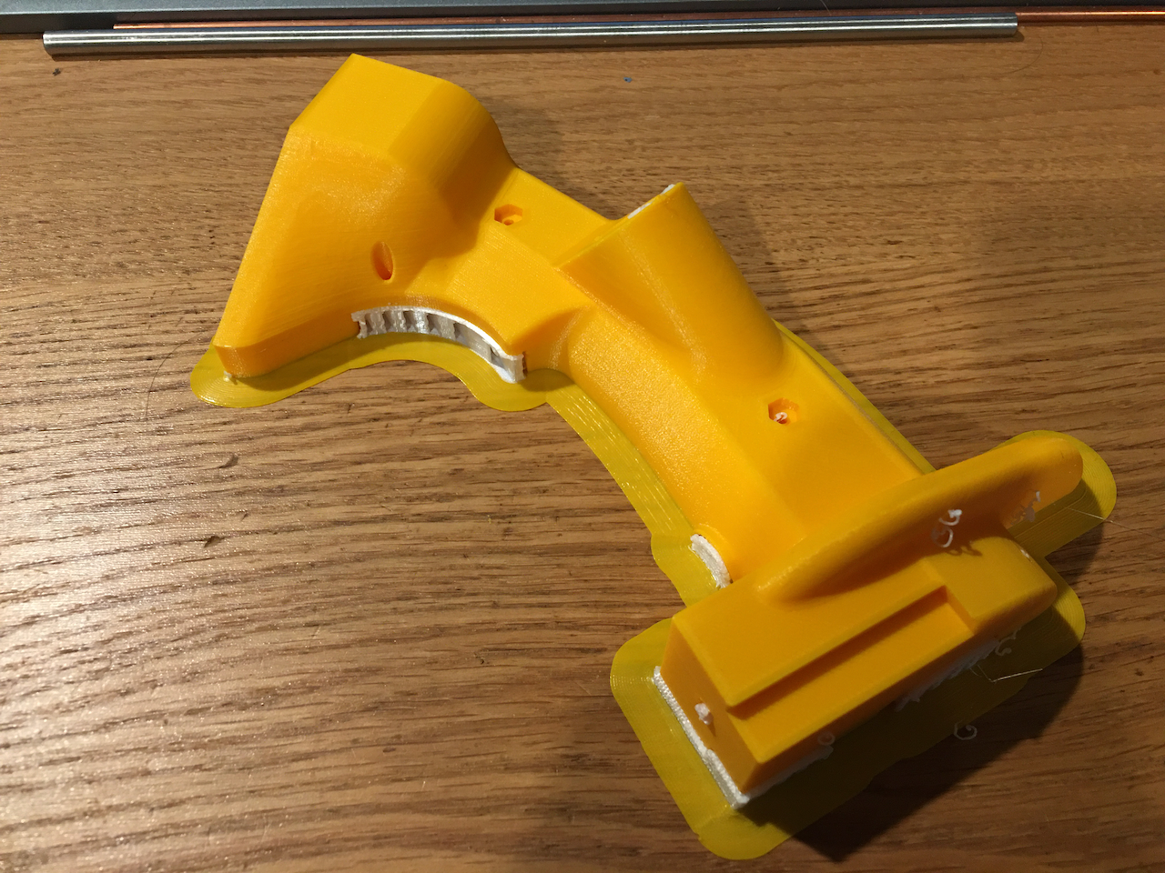
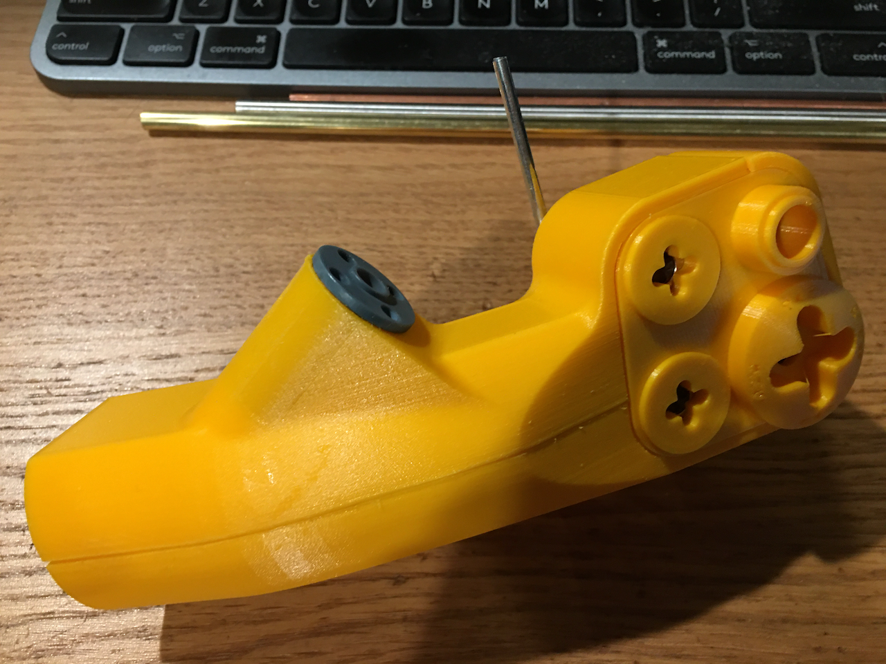
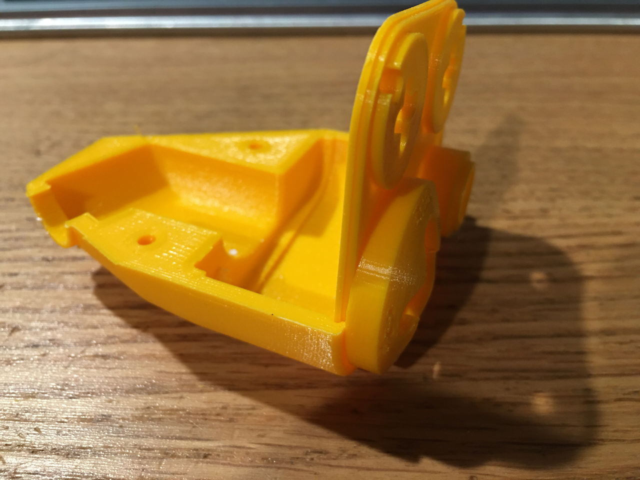
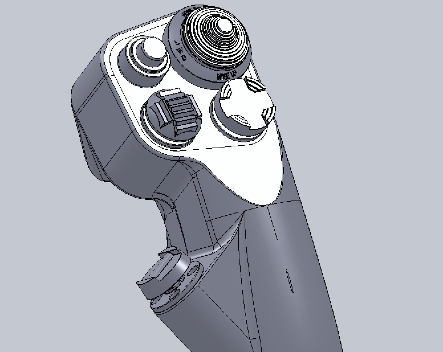
Fits like a glove, see picture #1. Added a "ridge" in the main control "face plate" and a "slit" in the top cover and main body to mate with each other, so I can get rid of the 4x screws that come out to the main control face plate. (In the picture, the test print for fitting still has the 4x screws holes cut in the face plate, but the final modification doesn't have them anymore. Also inside, the main tube was originally designed to have one and only one curvature, on the idea that it can be slipped into the printed body without having to split the main body into two halves. I have regretted that decision, because bending an OD=1" aluminum tube in such precision would require some serious mold and equipments. So, I have changed the tube to be composed of 1 straight tube, bend in the middle with a generous radius of 3". Most likely, this can be made with some carved wood blocks and a hydraulic press (or a sledge hammer if you feel lucky). Depending on your "precision" in the bending, I will put in a "tolerance" value so that "hole" can be adjusted for fitting (and then you can Bondo it to fill the gap between the tube and the body). This took the whole Sunday afternoon to "correct" all the constraint errors showing up. Grr.... Also, I have changed the internal wire routing. 1. make the internal M2x25 screws be Nylon, i.e. abandon the idea of using the screws as signal path, and 2. dig in the air vent channel deeper to accommodate wiring. But, now I need to figure out a reliable way to contact signal pads. Most likely, it will be just some copper disks with wires soldered to the back annular copper pads on PCB. The abandoning of using the screws as a signal conduit was prompted by the fact that some of the annular rings on PCB made by OshPark now are bigger. For several batches and different revisions of PCBs, I was able to get reliable contact between the screws and the gold plated copper annular rings... but no more. The recent two batches.... the ID of the annular rings are slightly bigger and do not make reliable contact.... So, it's a bad idea to rely on this "unspecified" manufacturing tolerance. Again, all these problems have to be resolved one at a time through prototyping, as this is brand new never done before designs, even the construction methods are brand new (at least to me). null
-
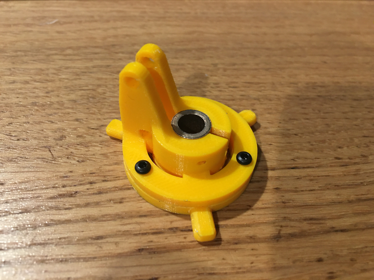
The socket button head M2x6 alloy steel screws are delivered.The next minor modification is already being printed. What you see here is assembled outside the tube. But the reality is that the bottom plate has to slip into the tube from the side slits and flipped around inside the tube into position. Then, the top one has to go in from the other opening end of the tube, and then screwed into the bottom plate directly in-situ. My SwissTools 1.5mm by 80mm long Allen Wrench is just barely long enough. After magnetizing my Allen Wrench, the new alloy steel screws worked well, except that the "bite" into the nuts is a bit shallow. So, I am adding an 1mm recess for the button head to sit in, increasing the bite of the threads. I didn't model the self-lubricating bronze sleeve bearing in the 3D model, but did designed the hole for it with correct tolerance accounting for a 0.4mm nozzle so that it needs to be pressed into the hole, just like proper interference fit. It took several trial-n-error print to get the right number dialed in. The next thing to tackle... the shaft and sensor seat, and wire routing.
-
Again... stuck, waiting for part. Story of my life. For screws, I usually prefer stainless steel whenever I can, b/c they don't rust. Less maintenance and all that, you know. So, most of the screws I have at home are stainless steel. One of the parts, the mystery part to restore linearity of the stick base requires 3 M2x6 screws. Of course I have stainless steel socket head screws and nuts ready for the prototype. One unforeseen problem was... damned thing isn't magnetic. So, I have hell of a trouble getting the screws inside the long tube in position -- they just won't stick to the Allen Wrench... Aaahhh... I have designed the thing in two parts so the thin part will go through the cut slits and flip over to lie flat, and the thick part (the real working portion) will go from the bottom and then screwed into the thin part to fix it in. I mean, I considered the details up to how to assemble the part and how much space it needs to maneuver the parts in position etc. etc. and all worked out (with minor modifications). I didn't see the non-magnetic 304 stainless steel screw problem coming! Ha! So, I just ordered some alloy steel M2x6 socket head screws... now wait.
-
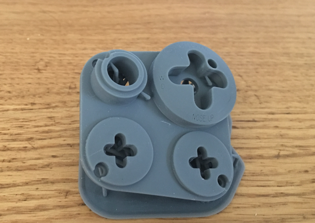
Printed with my Phrozen Mini-8K. Mighty-8K is still having some trouble, probably needs a new nFEP film. The bottom recess does not print too well, but with some manual fixing, should work. The thing is... PLA printed, the back printed perfectly... with some epoxy filler and sanding, it should be as good as the 8K. Unfortunately though... the text just doesn't work at all with 0.4mm nozzle. The text on SLA prints is a bit too fine. Needs to make them bold or something.
-
Would you mind providing some hard numbers other than baby’s ass? I would like to remind you that baby’s bottom is what’s smooth, and baby’s ass is where bio waste comes out.
-
Oh ya… 3080 here too. High texture, Andersen AFB, AH64 on the ground, with the OTT desktop resolution 800x600 trick, and I get 12fps to 2fps, unplayable. Switched to medium texture, 45fps.
-
One too many argument, I think. If I remember correctly, the signature is something like MapKey(Device& device, int button, int key);
-
If I have to guess, it's probably one of the what I call Markdown Minefield. MapKey(&Throttle,MSU,0,0); When you post code in the Markdown Idiocy Era, you better do the <pre> </pre>, or use whatever "Code" markup there is available.
-
Do you see the comma in the screenshot? I not only don’t see comma in your original post, in the quote, I don’t see it in the screenshot either.
-
Don’t see no comma. The correct syntax should be MapKey(&Throttle, MSU); As to whether the semantics is correct or not, no idea.
-
Missing a comma between &Throttle and MSU? Syntax error.
-
Yes. But, it’s cheaper if you just buy an SLA printer and print them yourself. Genuine backlighted knobs (transilluminated knobs, http://www.ehcknobs.com/index.php?id=TM) are very expensive. Could be USD$60 a pop, could be $25 a pop. Just go to EHC, look for the ones you want and google the part # and see what you find. And try eBay too for surplus (could be $5 a pop). Farnell, Newark, Digikey, and Mouse carry some limited stock. EHC might bother lifting their fingers if you buy more than 50 for one part #. Seriously, at such prices, it’s cheaper to buy a 3D printer. Sure, 3D printed knobs might not be as durable as injection molded genuine articles, but if they break, just print more. To get you started, go here, https://github.com/JonahTsai/F16, to get some 3D models for knobs and buttons. Or, you can have Shapeways print them for you.
-
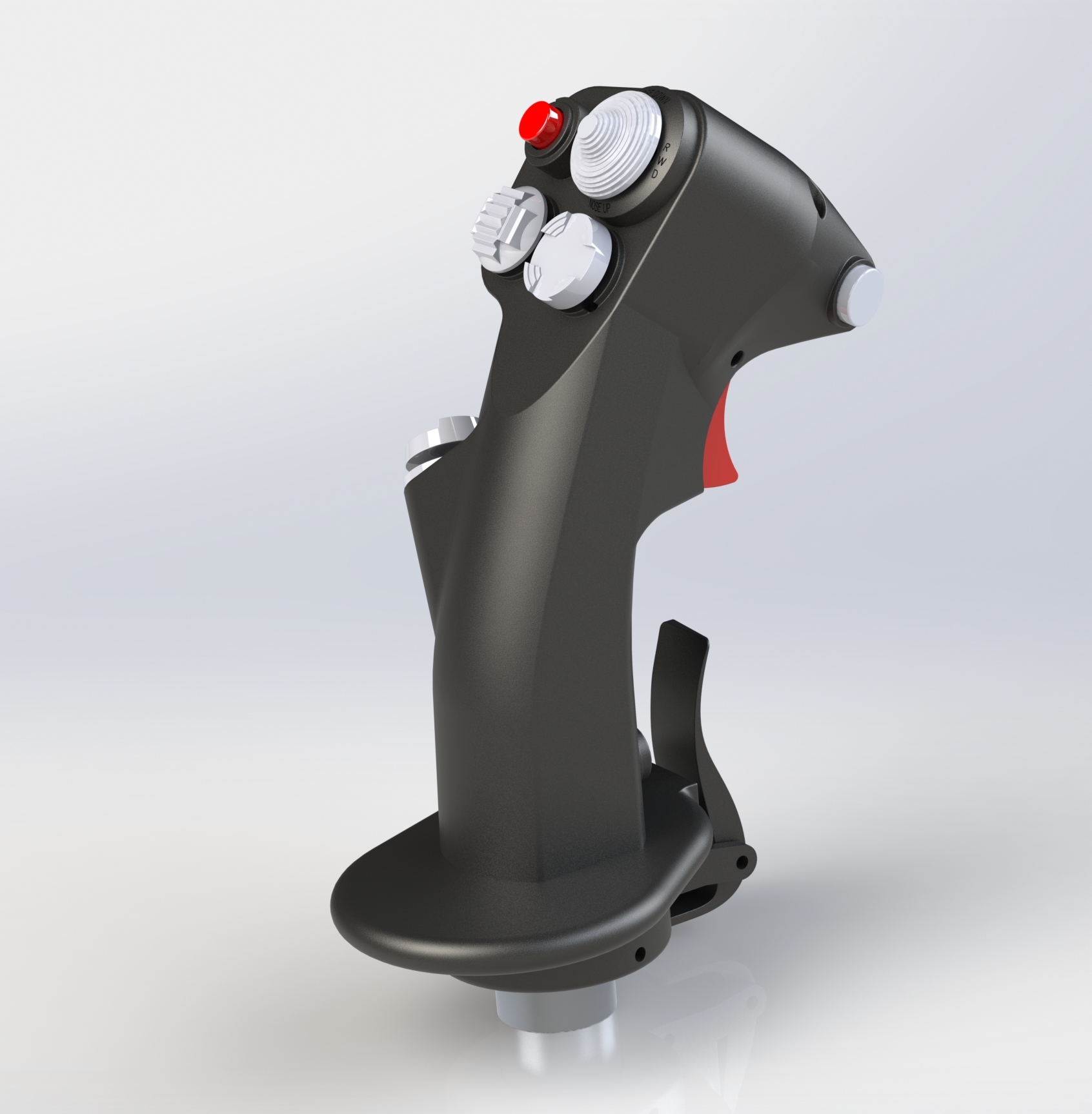
Just 2 test renderings with my new Solidworks 2023 Premium.... on my gaming rig.