Hempstead
-
Posts
473 -
Joined
-
Last visited
Content Type
Profiles
Forums
Events
Everything posted by Hempstead
-
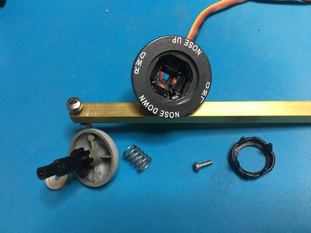
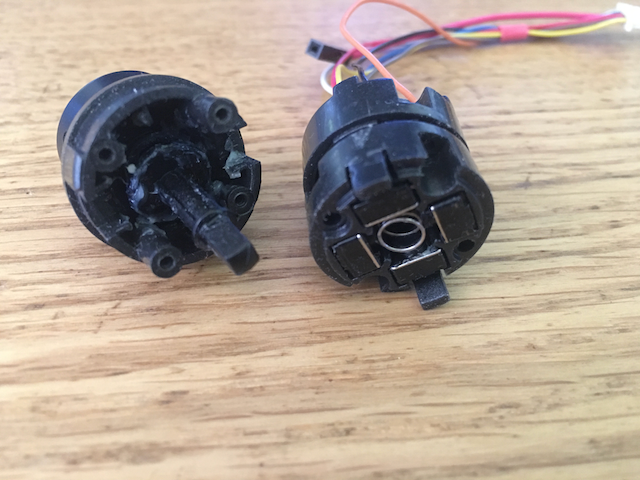
Yes... I did replaced the whole trim, bought from TM -- the only source for it. So, either you buy the whole thing from TM, or you replace the mini-pushbuttons inside. My all optical replacement of my own design... is not for sale. But you don't really need to replace the whole thing unless the shaft or the case is broken. If it's just the switches/buttons... nullViper trim switch internally has the same design as throttle's MIC switch and other HAT switches -- 4 mini pushbuttons in each direction, see attached picture. The only difference is that it does not have the down push provision. So, its casing design is a one piece instead of 3 pieces. Please refer to this thread, where Sokol provided the exact part # for replacement of the mini-pushbutton. You will need to solder the wires though.

-

ExpressPCB advice sought for non rectangular boards
Hempstead replied to lesthegrngo's topic in Home Cockpits
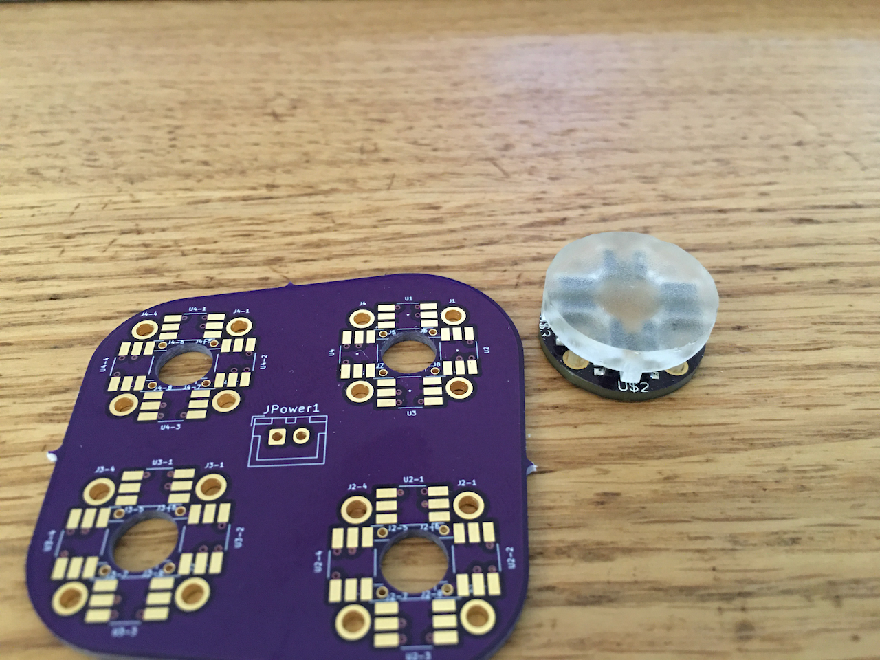
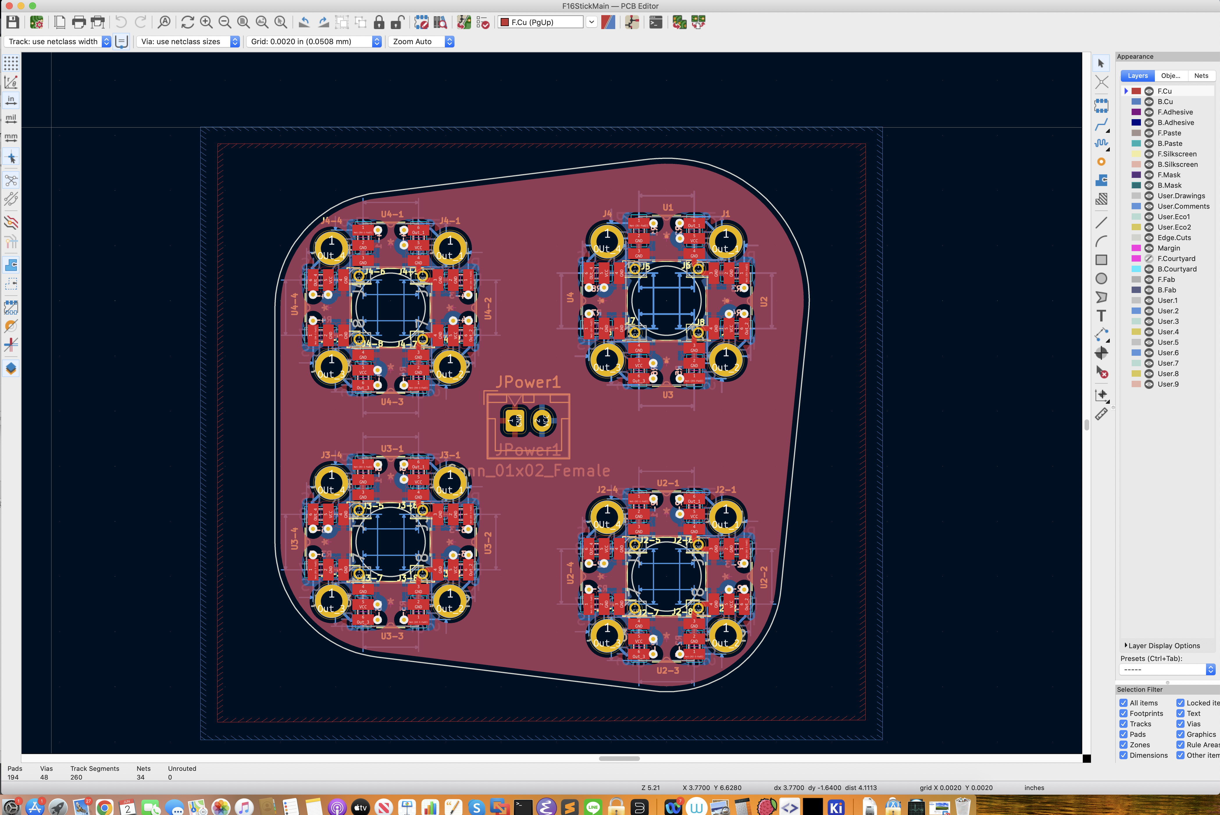
I highly recommend on learning KiCAD. I have been perfecting my CNC PCB milling techniques for years... I am able to produce consistent 10 mil tracks with 5 mils cutters (ok... 5 mils cutter are very expensive and very prone to break so I usually use 10 mil cutter if I could.). That's actually very difficult to achieve consistently. Any mistake, you pay the price of a solid carbide cutter. Lots of tricks to get it to work consistently... but I eventually gave up... not because I couldn't do it. The reason is mainly because of what OP alluded to... the via. My circuits are becoming increasingly complex (try design an RPi UPS circuit without via!). The need for via, a lot of them, is undeniable. I have some expensive copper via rivets, and anvils... very expensive, and they do work. But it's just too much work for other than a few via. Sure, you can use just a bare copper wire and solder instead of via... but the thing is that it's still very labor intensive. For a small one off board, or two, it's ok. More than that, it's a PITA! The same via trouble applies to chemically etched PCBs. I have been using Eagle for a long time, since the TM Cougar days, (I have several non-commercial licenses), and absolutely refused to go with the AutoDesk subscription model. I had also been playing with KiCAD since the 90's and completely dismissed it then. However, KiCAD has really grown up tremendously in the recent few years (V. 5+). It's now quite good for my purposes. So, I finally took the plunge and learned KiCAD, and am stopping any new development using EagleCAD. If you are in the US, I would highly recommend using OshPark PCB service. No fuzz, great services, and fast (ok, relatively fast). Let me tell you my bad experience with one of them Chinese board houses (this does not just apply to Chinese ones). I had been using OshPark for quite a bit... but I decided to give one of those Chinese board houses a try. So, I downloaded their ERC rules and ran through my circuit design. It's just a sensor board... not much really, there is no MCU or anything complicated on it. You know, a simple test case to run through the process, and all that. So, I submitted the order. And a day or two later. I got an email asking me to correct a violation of the board house rule, something about a trace too close to the annular ring. Fine, I corrected it. And a day later, I got another email about yet another violation.... I corrected it. Note that... OshPark had no trouble producing these perfectly. Whatever,.... this one violation/correction at a time thing went on for about a week and I finally had enough, and gave up and requested a refund. They politely apologized and promptly refunded, no bad feelings. But... Ok... I am not a professional EE engineer. I am mainly a software engineer, but a born tinkerer. I am quite sure there are a lot of good reasons why these board house rules exist. But, rigorous process is one thing... a process that is time consuming and border line bureaucratic is another thing. For goodness sake, just tell me all the violations and let me deal with them in one shot instead of one at a time. What is this? Chinese water torture? What I am saying is... those Chinese board houses, and other US board houses as well (even my Seattle suburb has 3 professional board houses, and I don't bother with them), they mainly cater to professionals who know WTH they are doing. People like us... are in the corner of who don't know WTH they are doing. And the professionals' volumes make it worthwhile to go through those professional board houses' rigorous rules. I am not saying OshPark is unprofessional. OshPark's business model is that they cater to small tinkers' like us. Collect orders and put them all on a whole board and send it to the professional board houses to be made. They are more tolerant to those little things that don't matter to us unprofessionals (or ignorant of them). And sometimes, I have some small violations that I know of, and deem irrelevant, OshPark would accept them and make them the way your design is... right or wrong, instead of rejecting your design and make a fuzz. Although I have never seen OshPark made PCBs came out unexpected, it could happen. Since OshPark caters to small "unprofessionals" like us, they make their process easier for us to get through than those professional board houses. What I am really saying is that if the Chinese board houses want to "invade" the business of the unprofessionals, they have a long way to go! My local professional board houses don't even try to get into that market. A warning about OshPark's service though. They are less rigorous in rejecting your design. So, you should make sure your design is really what you want. OshPark will make them exactly as your design file says. I had one design that was totally my fault... and I had to correct and reorder it. With EagleCAD, you can just drag the .brd file to OshPark order page and they will run a script in the back for generation etc... Can't do that with professional board houses! For KiCAD, OshPark does not accept the board file directly. You are supposed to export them as Gerber files and generate drill files, zip it up and drag it over to OshPark's order page. Easy peasy. Attached in the picture is two PCBs made by OshPark. On the right is a standalone 8-way optical PCB for stuff like MIC switch, and any HAT. It has a provision for pushbutton as well (same PCB, but have to manually cut a trace). All optical, including the pushbutton. The rest of the mechanism are all 3D printed, or made with simple tools commonly found in typical garages (and buy some special tools like a 4mm reamer). The transparent thing on the standalone PCB is a soldering jig. It's there to position the optical sensors accurately in position with positional tolerance around 0.1mm. This was originally designed in EAGLE 7.x. And I recently redid it in KiCAD 6. On the left... that shape should be familiar to you. It's for the F16 control stick, all optical (the upper left circuit is indeed for pushbutton for weapon release button, just populates one optical sensor instead of 4). It's also designed in KiCAD, using a replicating add-on so I don't have to re-layout the same traces (tricky enough for one) 3 more times. That, Eagle 7 cannot do (don't know about Eagle 9, and don't care). Just look at the circuits... 3 via holes per sensor. That's 48 via holes, plus 16 for Vcc and GND (sorry, this design require them to be via holes). That's total 64 via holes. And that's for just one PCB! I am not doing that by hand! And this is just a PCB for sensors, nothing complicated! With OshPark, minimal order is 3 PCBs. That F16 control stick head PCB costs about USD $19 for 3, plus free s/h if you select USPS. I opted for FedEx for about $8. They shipped it out about 8 days after I ordered it. OshPark is in Oregon. So, time your s/h time with that.
-
Track file replay shows me crashing, but I didn't really crash... ?
Hempstead replied to Fulgrim's topic in General Bugs
Replay is definitely bugged regarding carrier landing. I just recorded another track of carrier landing... replayed back immediately... touched nothing. The balked landing worked just fine... the last real landing, it did not veer off, however it does not catch the wire, and it started veering off. However, my F16 aerial refueling track files recorded and replayed just fine, new and old track files. -
A simple solution of cockpit click in VR: Finger-ring touch mouse
Hempstead replied to Jenson's topic in Virtual Reality
I quite like the way Oculus Touch Controller is implemented in DCS. It's not perfect, but it's useable. The laser pointer thing lets me not have to reach out to the virtual switch/button location and ram my finger tips into something hard IRL. Plus, the LeapMotion thing never worked on my machine (no video on Windows at all, never mind DCS). At a flick of my wrist, I can easily reach any button/switch in the cockpit. The only gripes I have are: 1. Every time I need to flip a switch or press a button, I have to reach out and grab the touch controller (it's right in front of the throttle/stick, right next to the TM logo) but still it's annoying having to fumble with the controller. 2. There is no HAT on the touch controller to bind to the dobber... Well, for #2, I configured the Left: Y as a modifier and then use the stick trim HAT + plus the Left: Y for dobber control; not ideal, but workable. But #1.... well in the redneck test in the video linked below, I simply drilled two holes in the touch controller's battery cover, uses a twist tie as hinge, and the factory lanyard as the anchor. This is just to test whether the whole idea is gaga... and where the attachment point is ideal. The final implementation will be sewn into the compression glove I wore in the video. I tried an USAF issued glove... don't like it... too thick for my taste. Up to you really. Edit: Flew an F16 aerial refueling with the redneck version. Worked great! The controller did slide on the lanyard... out of position. But a twist of the controller 360 degree, pivoting on the twist tie center worked great in preventing it from sliding on the lanyard. Of course, the final version sewn one would have this problem. -
Track file replay shows me crashing, but I didn't really crash... ?
Hempstead replied to Fulgrim's topic in General Bugs
Are you saying you don't see this behavior in replay? Also, I should add that, while it's doing the veering right, I could see there is no input to the simulated control stick doing the severe right banking. And, the control stick would still show the small banking right/left, and the aircraft would bank right/left accordingly, just with that extra out of nowhere banking/turning right. I have not tried newly recorded track files... I should try record another track with this version and replay and see if it happens again to help ED narrow this down, instead of categorically blaming it on replay imprecision. -
You may not need to replace it... yet. First, open it up and take the switch out. Carefully open it up, and make sure you take a picture of the wiring (color of wires, so in case you dislodge the wires, you know which goes to which in order to solder them back. The soldering and wiring is a bit fragile. Inside, there are four mini-pushbuttons sitting on each side, N-E-S-W, see the attached picture. You can buy some from SparkFun to replace them. Should be this one, https://www.sparkfun.com/products/97. But I can't guarantee it, as I can't find that bag of mine I bought. But the case dimension should be 7x7x3.5mm (excluding the button part. Note that you will need to modify the leads a bit and solder them in place. Or, if you are adventurous, you can open the mini-pushbuttons, and clean them up... reassemble, and you should be fine. I have done the cleaning with an air compressor and some electronic contact reviving solution like 3 times with my Warthog throttle MIC switch... (inside, they are all the same construction), before I had to buy spare part of the whole thing from Thrustmaster (something else broke). null
-
Thrusmaster Cougar Throttle, Anti Static Tape, used for Travel MOD??
Hempstead replied to Dispatch's topic in Thrustmaster
PTFE tape, if I recall correctly. You'd need some kind of one side bondable PTFE tape/sheet... Otherwise, nothing sticks to PTFE. Not epoxy, not superglue, pretty much nothing. You will have to find either one side bondable PTFE tape or find some other mechanical fastening method. -
Track file replay shows me crashing, but I didn't really crash... ?
Hempstead replied to Fulgrim's topic in General Bugs
Well... I am seeing something like that too... I have like 6 track files for F18 carrier landings, all of them good landings. I have even replayed them for friends... no problem. But today, I replayed on of them... all good... until I turned final and the meatball overlay shows up... and it just veer right slowly, and keep turning right and descend, and eventually into the sea. Then I replayed all other 5... all the same... as soon as the meatball overlay showed up, they all do exactly the same to the right and into the sea. Imprecision can't be that imprecise! I am a programmer. I don't believe one bit this is imprecision or rounding error... I mean, common... going straight versus sharply veer right can't be explained with imprecision... no way! It's just too big a difference. Something about the replay changed and broke it! And all 6 track files??? -
Apology for necro'ing the thread. This is the closes thread I can find. 1. Just because it's close to RL is not a good reason for rejecting the problem. If it were, then, there is no justification for the carrier meatball overlay. RL doesn't use a Thrustmaster Warthog controller, nor does it use Q2 Touch Controllers. One simply cannot ignore the differences between RL and simulated situations and limitations. In other words, practicalities of simulator needs to be compensated. The meatball overlay is a good example that ED team does consider that. 2. In VR... particularly in Q2, it's almost impossible to see the indicator light. I myself could occasionally see the left U/D light, but have never ever seen the F/B light. 3. I am seeing a tanker bug I have not seen mentioned after some searches. That is, if I get too close to the belly of the KC135, sometimes it would tell me Return To Pre-Contact. And turn off the light, and will not contact with the boom anymore. What's worse... sometimes it doesn't say "Return to Pre-Contact", but turned off the light and will not contact anymore. Now, since it's so difficult to see the indicator light, I would have no way of knowing whether I need to "Abort refueling", and then "Ready for Pre-Contact" again. This bug is exacerbated by by the difficulty in seeing indicator lights in VR. I sincerely hope that ED will consider adding an indicator light overlay just like with the carrier meatball light.... and investigates/fixes the lights off, no contact, and no communication situation.
-
I use two pieces of marble slabs. You know, those ones used for making pie crust (not cheap, mind you!). One on the front to weight down the front metal lip and prevent it from sliding forward. One on the rear (in reference to the aircrafts) to weigh down the rear metal lip to prevent it from tipping over and to boost the floor height by about 1" for my heels. After I praised the TPR, I feel obliged to tell you what I think the two solvable problems with TPR. The trouble is that the TPR pedal height is about 3.5" center to floor (the axel center height). F16 has about 2.5". So, TPR is slightly too high, even for a reclined sitting situation. It's good for if you were lying down in a pit with a highly reclined ejection seat a foot from the floor, with a pair of USAF issued boots which boosts your heel height... but if you are sitting in an office chair... your leg angle is way too steep, and you are bare footed on carpet.... both factors reduce the effective height of your heels and makes it quite uncomfortable. So, that extra 1" thick of marble slab made a huge difference for me. Plus, this kind of marble slab is very smooth but not mirror slick, great for sliding the heels on it when maneuvering aggressively, much better than carpet. Moreover, I don't want my carpet to have two bare threaded "pedal tracks." Even though TPR has the provision to adjust the angle of the pedals to suit office chair sitting situation, it's, nevertheless, not very good. The trouble here is that at that angle, you would have to lift your heels off the floor in order to reach for the toe brakes and press down (our feet have surprisingly little range of motion for tiling up and down, about 45 to 50 degree only), but there is no provision for heel support. So, your feet are kind of dangling half in the air with no reference, making centering very difficult unless you have strong springs to center it for you. And the dangling half is where the gravity is pulling down on your whole lower leg. Not good ergonomics. I prefer to fly with my heels on the floor, thus giving me a relative location reference for fine adjustments. So, I usually fly with my toes on the pedals and heels on the floor. 3.5" is way too high for that when sitting on a high office chair (awkward foot angle). When making large movement, I move my heels. But for fine adjustment, I tilt my feet without moving my heels. And I only put my heel off the floor and reach for the toe brakes when I am landing or taxiing. Hey, 99% of time I am in the air, not on the ground. So, I favor the solution that give me better in the air performance. After all... most of the aircrafts are like swans... they only waddle badly on the ground, particularly the F16s with its narrow wheel base. I am sure somebody could easily design and print a heel support for it. I, myself, don't want heel supports. I want my heels on the floor, a boosted floor, or the pedal height should have been lower, much lower. If I had to guess... I would guess the heel support was cut for cost saving. Things like that are always tempting targets for cost saving measures. Moreover, if you look at the aluminum arms where the pedals axels are attached to, you would see some casted features that currently have no function.... but they look like stops and notches for attaching some kind of heel support option. These... probably some would argue that it's a personal taste... kind of... but they really are ergonomic design issues that aren't solved. The reason I said that is that for an office chair sitting, you need to tilt the pedal angle down to fit the range of motion of our feet (TM did that), and either design in heel support, or lower the pedal height (probably to about 1" for heel on floor). But if you want your pedals to support both reclined sitting and office chair situations, you probably would be wise to make the height adjustable (say make it 1" high, but supply a couple of cheap booster blocks), and make the heel support a detachable option. TM did neither. So, IMHO, it's a design miss, but also possibly a business decision miss. But they can be easily redheck'd. So, not a big problem. You know, if I can't easily cut the pedal height down... I can boost the floor height for my heels!
-
Try Lee Spring online.... tons of in stock springs... but, for small quantity, the markups is quite high, and the s/h is another killer. Or you can just make some springs with piano wires. This type of tension spring is very easy to make... a mandrel plus a cordless drill, and some simple wooden jig will do just fine.
-
Center is pretty good. I haven't opened it yet. But AFAIK, they still advertise the H.E.A.R.T system, i.e. MLX90316/MLX90333 run under a 3-wire SPI mode. So is the TFRP. The toe brakes look like some linear sensor. Don't know what they are. Could be just some simple linear POTs, could be some linear Hall sensors, could be magnetic linear POTs. Don't know. Anyway, the main response curve is linear, no dead center, no sticktion I can detect (shouldn't have much as it's pretty much a parallelogram mechanism, so only poor bearing/sleeve quality could mess that up). At center, fine adjustment is only limited by the centering force generated by two springs with an adjustable mechanism. If you are flying choppers, you really don't want too much centering force. So, unless you add damper(s), there should be no sticktion to hamper your fine adjustment (the main reason I ditched TFRP). You can use one spring, or two springs. And the fine adjustment can be done with thumb screws (IMHO, superfluous, as I can't feel the difference with the bottom of my bare feet with the range of the adjustment, but some might like it). One spring vs two spring, however, makes a huge difference. Since the two springs are exposed outside of the "casing", you can easily replace them.
-
TPR has pretty much a linear force response curve. It's basically a parallelogram design with half of the parallelogram folded to sit in the back of the tower. It still has a central torsion spring reacting to rotation of a pivot bar. So, linear to the rotational angle.
-
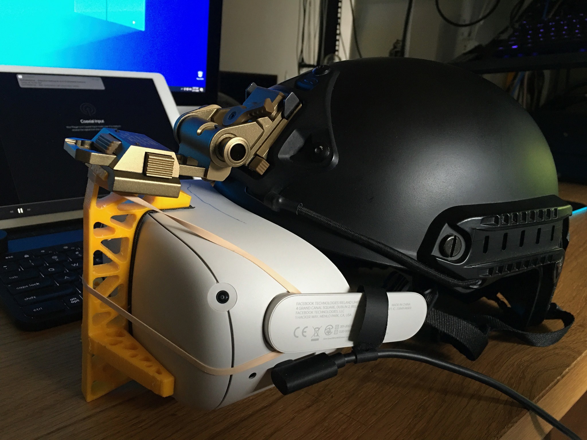
I have posted this before (not with the STL file). It's just a simple 3D printed PLA adapter for the Wilcox NVG adapter (the lip of the helmet on the front does need to be cut a little for the Q2 to slid closer to your eyes (just cut it as high as you could without cutting into the NVG adapter on the helmet; you do have to take out the padding right inside before cutting), but nothing a scroll saw couldn't handle, if you just buy the el'cheapo plastic helmet for Airsoft, instead the very expensive combat version made with Kevlar. I can use this for hours. Sure, there is some light leaks... not that I mind much... you can always put some black cloth bag over it; problem solved. Currently, a clone aluminum Wilcox adapter sells for about USD $100, and a cheap helmet about $30 on Amazon. So, it's $130 plus a little elbow grease vs Elite strap's $49 which kind of works but not really well. Attached is the zip file with the adapter's STL file. I hereby put it in the public domain. Do whatever you want with it. I don't give a rat's mule. Please note that you should print it with a 0.4mm nozzle. PLA will do just fine... no need for tough PLA, or Nylon, or ABS, or any exotic carbon fiber filament. Also, I would recommend that you print it with the flat side of the spine down on the print bed so to avoid delamination of the dovetail where the concentration of force is, and less support material needed. It's designed to be printed this way. Print it in any other orientation, and it might fail. In this version, I had gotten rid of the holes on the body. They don't save much material, nor save much print time, and waste a lot of breakaway support material and a lot more post processing works to get rid of them. A 40% infill with no holes will do just as well. I also put a tennis racket grip tape on the Q2 to protect it from scratches from the printed adapter. In addition, I have replaced the rubber band with a flexible cord similar to the ones on the helmet in the picture. A shoe lace would do just great too. Let me know if you want the original Solidworks file for modifications (exceeds the 5MB attachment size limit of the forum). NVGWilcoxLock2.STL.zip
-
TM Warthog (Thrust lever) & TM Rudder Pedals both using Joy-Z problem
Hempstead replied to FopaUK's topic in Thrustmaster
They are both JoyZ but from different devices. I know, it's confusing, but a lot of game GUIs don't display which devices it comes from. That includes MSFS 2020, Elite Dangerous, DCS, and even BattleField games. However, underneath the games do record the devices:control tuples. If you bind them by using the button/key presses, you'd be fine. But if you use drop down list... that could be confusing... Brevity is a good thing, but not at the expense of clarity! -
I would suggest drilling a tiny hole on the stick body at the location of the clip, a hole just big enough for a paper clip. It’s not dissimilar to the mechanical SIM card ejection “hole.” TM should have designed that in.
-
Universal military aircraft homecockpit project
Hempstead replied to Viper1970's topic in Home Cockpits
Yep. That JS5208 is the one I am using as well for F16/A10 thumb CMS switch where my new all optical 8-way won’t fit. It has one attribute that is much better than every other 8-way switch on the market I know of — the stem is reasonably long enough to get some thumb cap to attach to it. All others are stupidly short, like 1mm long nubs. So short that even superglue has trouble sticking to it for long term, as stupid as the Thrustmaster nub. Funny enough though. My inability to find an 8-way that does not just have a stupid nub, over the years, was one of the reasons that drove me to start thinking about designing my own. Then it progressed to, if I were going to bother with designing my own, I am gonna design one that has no electrical bounce, and solve that problem the soft debouncer in Hempstick couldn’t solve, once and for all. And the optical 8-way was started because I couldn’t resolve the pushbutton problem for my Hall Mini Stick design in my bronze cast F16 TQS. So I thought, If I could solve the pushbutton problem for the 8-way, I could back port it to the Mini Hall Stick. A chain of events all sparked by those stupid nubs! I blame that guy who designed that little red stick on IBM Stinkpad keyboard! -
Yeah, George is a huge problem w/o IFF. I have been killing Abram tanks b/c of it. Then I started playing Hammer campaign, killing more friendly Abrams. So, I stopped killing “Tank?” on George’s list. And then I kept getting killed by T72’s anti-tank laser guided rounds. No warning, no nothing, just bam, and dead. I had to find how I died by reviewing the event log after the game. George w/o IFF in combination with no laser warning is awful.
-
Linkage-less aircraft rudder pedals
Hempstead replied to Dragon1-1's topic in PC Hardware and Related Software
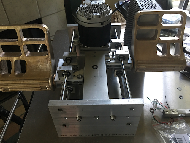
Something like this? 100% home made. But please note that this project has gone through 5 complete redesign, over the past 13 years. Even I myself couldn't wait for it and bought TM's TPR b/c I wanted to fly F16 and F18, and AH64 now, not next year. However, I am rather sure there will be no major redesign, as the main mechanism is working very well -- I have completely resolved the torque binding of the linear ball bearing problem that had been plaguing me for the last 10 years, once and for all. What's missing are: 1. The new Hempstick Pico to be able to drive the industrial servo motor and serve as an USB controller. 2. Force sensing toe brakes. Some partial prototypes in progress. 3. prototype the new pivot-bar-less modification. The picture is a bit old... the new modification has no central pivot bar... one less thing to make with milling machine. That reduced the parts requiring milling machine to a big fat zero (although a CNC milling machine would be nice to have in the manufacturing process). The designed force for the main axis is about 40 lbf, toe brake, 20 lbf. And NO FFB! Don't ask. I refuse to support FFB. It's possible to get it to work if you get rid of the motor and no toe brake, and put in spring centering, and other controllers, like the original Hempstick, or whatever other controllers. Obviously, I am not into that. It's a nice to have feature if I could cramp it in, but will be ditched in a heart bit if my main design conflict with it.
-
Core i9 7900X, 10 core RTX3080 32GB Oculus Q2 Able to run F16/F18 at 45 fps stable, except explosions and at carrier, device at 90Hz, max resolution but, AH64, 22fps to 8fps Reduced Oculus Q2 to the low recommended resolution, fps no change, still 22fps to 8fps, nausea inducing, unplayable. Update: I up the Q2 device resolution back to max, 90Hz... and changed DCS's general settings to VR preset. I was able to get wildly swinging fps between 8 and 30 fps, but mostly at around 30 fps, on the ground. Did a cold start... and then flew up... once I am up at around 200 ft agl, my fps returned to about stable 45 fps. So, it's definitely stuff on the ground causing the fps drop. Perhaps remove those fuel truck, guys with M4 standing guards and got killed by my landing (I forgot to bind the toe brakes so I mowed him over)? However, this thing has the tendency of swinging left and right slightly. I am no chopper pilot, not sure if this is normal.
-
Email Thrustmaster support. They will most likely sell you a replacement switch. TM is well-known for selling spare parts to extend your high end controller life span, unlike some other vendors.
-
TM Cougar & CH magnetoresistive/ hall sensor kits
Hempstead replied to rel4y's topic in Thrustmaster
Oh, whatever, screw it... Here it is. These three attached files are hereby published in the public domain. Do whatever you want with it. Note that the text is supposed to be about 0.915" to 0.1" high, or about 6.5pts to 7.2pts. I drew the "right" size... but it looked "funny." So I reduced the size to make the text look "better" but obviously undersized a bit. Anyway, don't count on the text size too much. They are very difficult to measure the correct size, unless you know your "fontography" in and out, and know where to measure. So, I often measure it roughly and adjust by how they "feel." Moreover, if you have enough authentic panels in your hand, you will soon realize the same thing I realized -- they don't all use the same font/size... In case you are wondering. The font I used, no surprise, is Gordon URW Condensed (GordonURWCond.otf/.ttf). TrimCacBody.SLDPRT TrimCap.SLDPRT TrimTop.SLDPRT Trim.SLDASM -
HOTAS Warthog, how much stick rotation is normal?
Hempstead replied to PSYKOnz's topic in PC Hardware and Related Software
2 or 3 degree rotation is Normal. Just don’t over tighten the stick to base. The plastic thread could bind onto the pot metal nut. So, when you next try to loosen the nut, you could break the internal anti-rotation plastic ball. -
Ideas for open Warthog base after spring replacement
Hempstead replied to PHMAC's topic in Thrustmaster
Ha! It ALWAYS happens that way, not just to you! Starts simple and snow balls from there. -
Ideas for open Warthog base after spring replacement
Hempstead replied to PHMAC's topic in Thrustmaster
A PVC pipe? Seriously, my first thought was 3D print a collar. But then a PVC pipe with a cut notch for the wire came to my mind in 10 seconds. But finding a PVC pipe with the exact dimension would be too good to be true, so why not make something like a ring cap on the top and bottom to cap fill the gap? 3D print would be nice, paper mache would work, a 2 layer cardboard disks glued together would be child play. You just want to keep dust out, right?