Hempstead
-
Posts
472 -
Joined
-
Last visited
Content Type
Profiles
Forums
Events
Everything posted by Hempstead
-
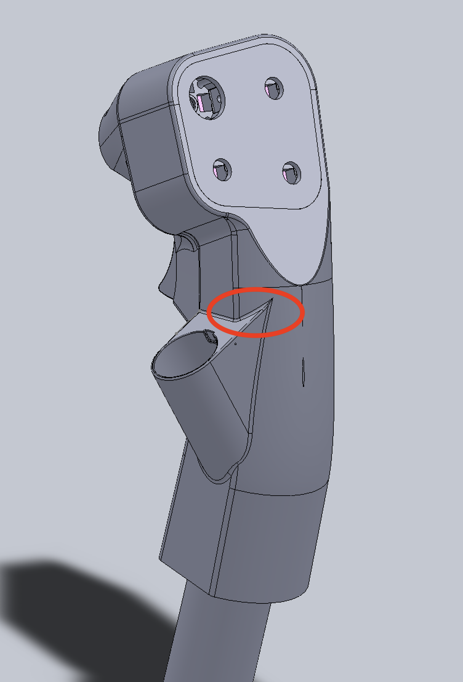
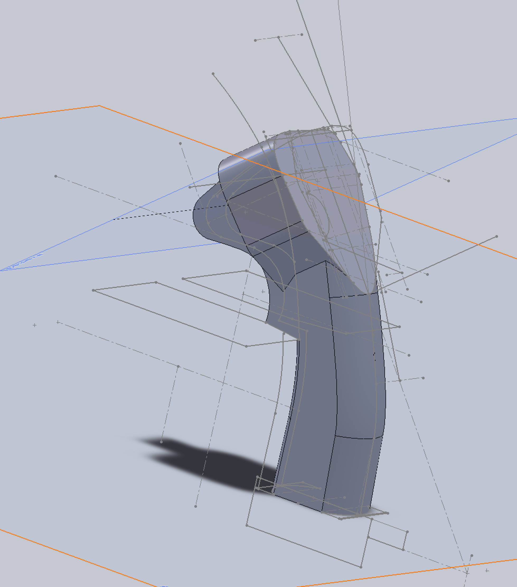
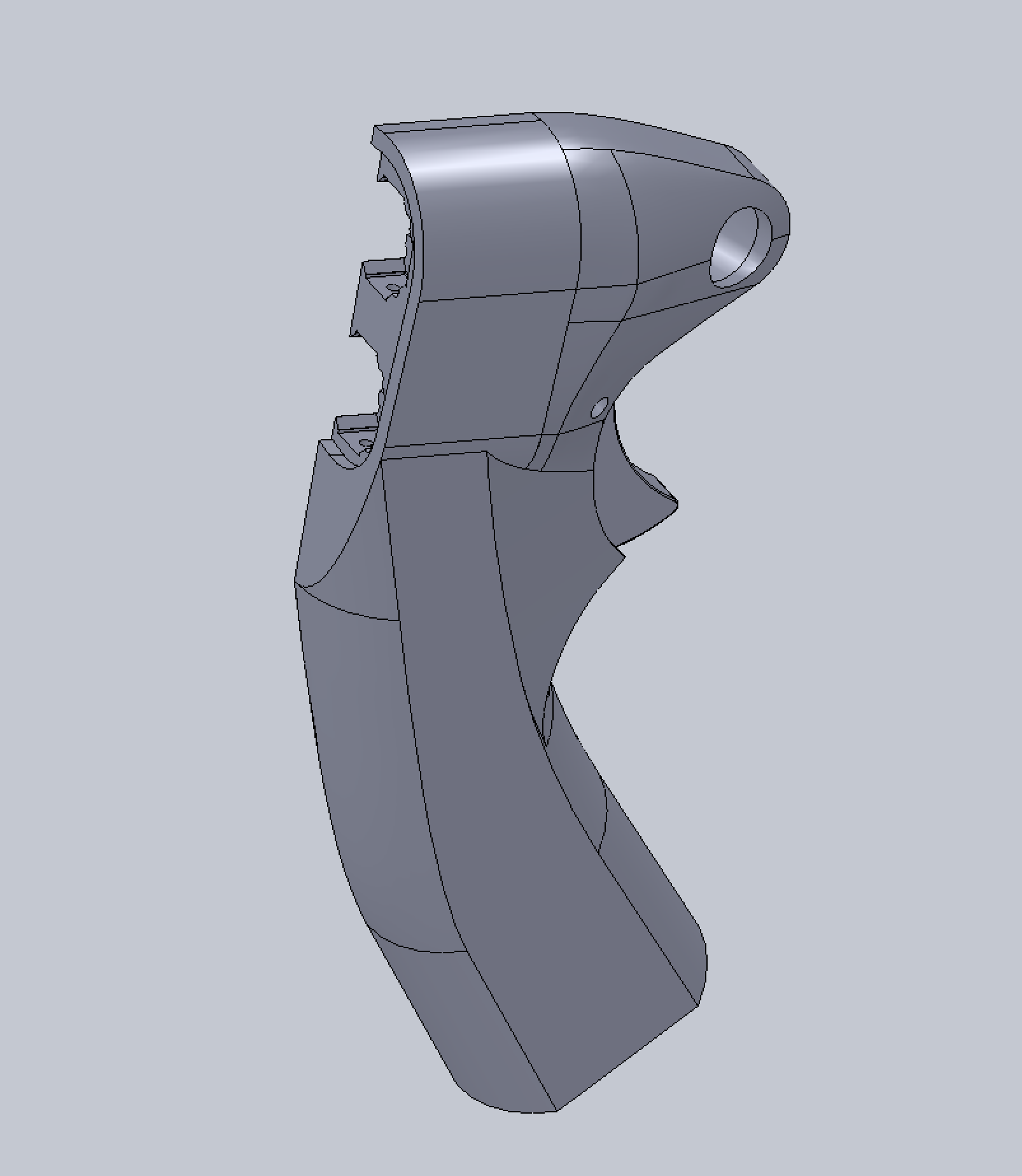
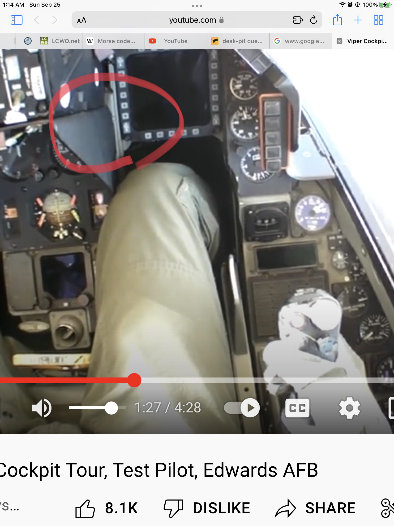
Added CMS "bump." Like I said, the "stem" and the trigger "forms" are based on TM Cougar, see the last screenshot. So, no surprise that when the CMS "bump" is modeled, it looks like the one on Cougar (the sharp triangle does not exists on Warthog, only on Cougar), see the red circle in the first screenshot. The cut out for the 5-way CMS HAT is designed to house my own design of 8-way optical HAT switch -- exactly the variation for the TM Warthog Throttle's MIC switch (a drop-in-replacement). You can probably drop in a TM MIC switch (but not fixing it in place). Also, one of the major gripes when I first got my TM Warhog stick was... man... where do I put my thumb? The CMS switch is so close to the main control "head" so that there is no space for my thumb. This solves the problem -- return to the Cougar form. I like the feel of Cougar stick better with which you put your thumb in the nook under the head (right above the red red circle in the first screenshot. But I did not like the form of the Cougar's control head form. Moreover, I subscribe to the Bauhaus school of Form Follows Function... well... I try to... most of the time. The last screenshot was the unfinished Cougar stick model. I stopped working on that one years ago because I didn't want to go the function follows form route. As years ago, I did not have the 8-way optical switch design, and I didn't want to use the "authentic" switches. BTW, the wall of the CMS "bump" is a bit thin... only 1mm thick. Should be ok... but I might re-enforce it on the inside at the root where it connects to the main body by thickening it a bit. Also, I ran out of space for the electronic assembly... colliding with the OTTO trigger a bit. So, I had to order thinner PCB, 0.8mm instead of the regular 1.6mm, from OshPark... still waiting for it. Next to tackle, the detachable "hand rest", and pinky switches. This will NOT be height adjustable like Saitek's. Put on some pads if you really want to adjust the height. Why go complicated?

-
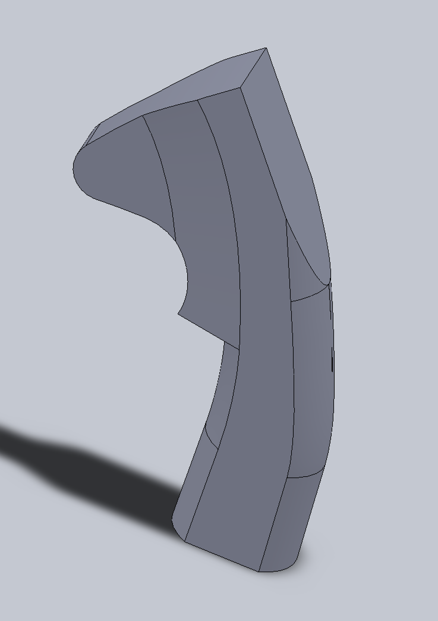
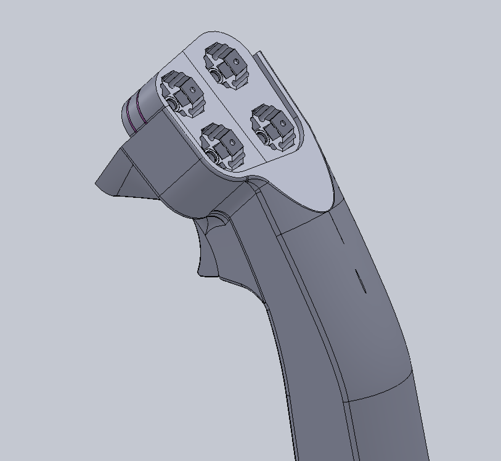
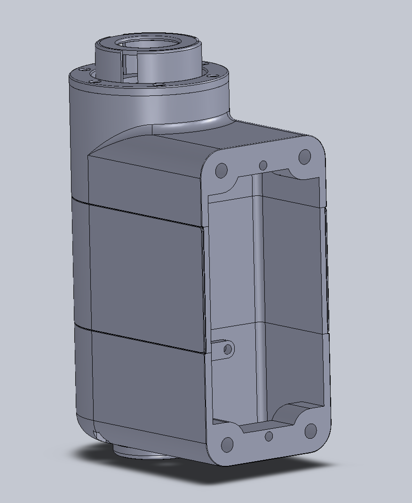
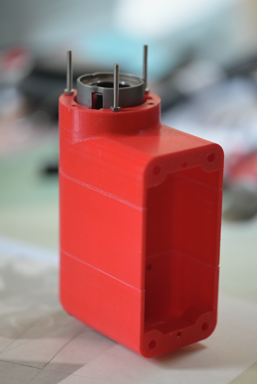
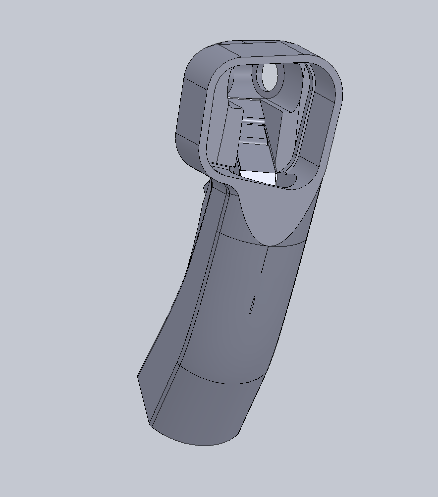
Faceplate cut off, top cut off, and a nekkid machine picture. From the nekkid picture, you can see the main design idea -- the components go in, the tube provide the main structural integrity for force transmission. The 3D printed stuff is just the "filler" to hold stuff in place, to transmit mainly compression forces to the structural tube, and for ergonomics. The outer Kevlar epoxy layer is just there to provide additional integrity for the plastic. I suspect if I print it with stuff like ABS or Phrozen's Onxy resin (8 seconds per layer) or the spanking new Onxy II (18 seconds per layer). The Kevlar/Epoxy layer can probably be omitted. nullnull
-
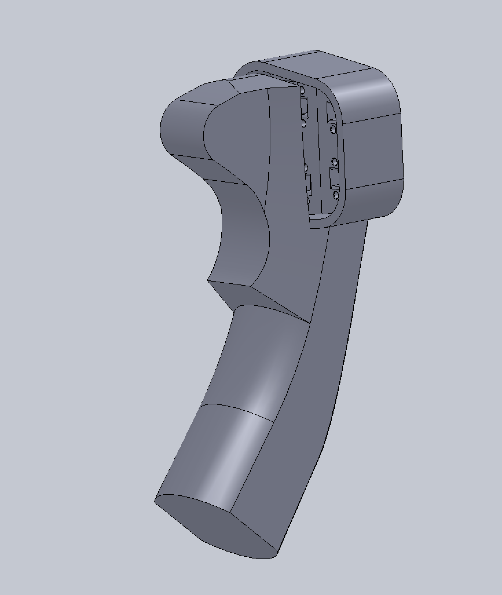
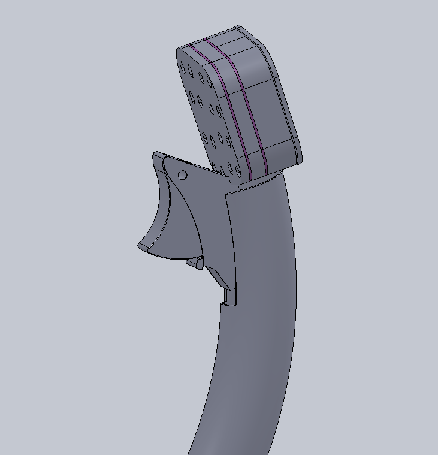
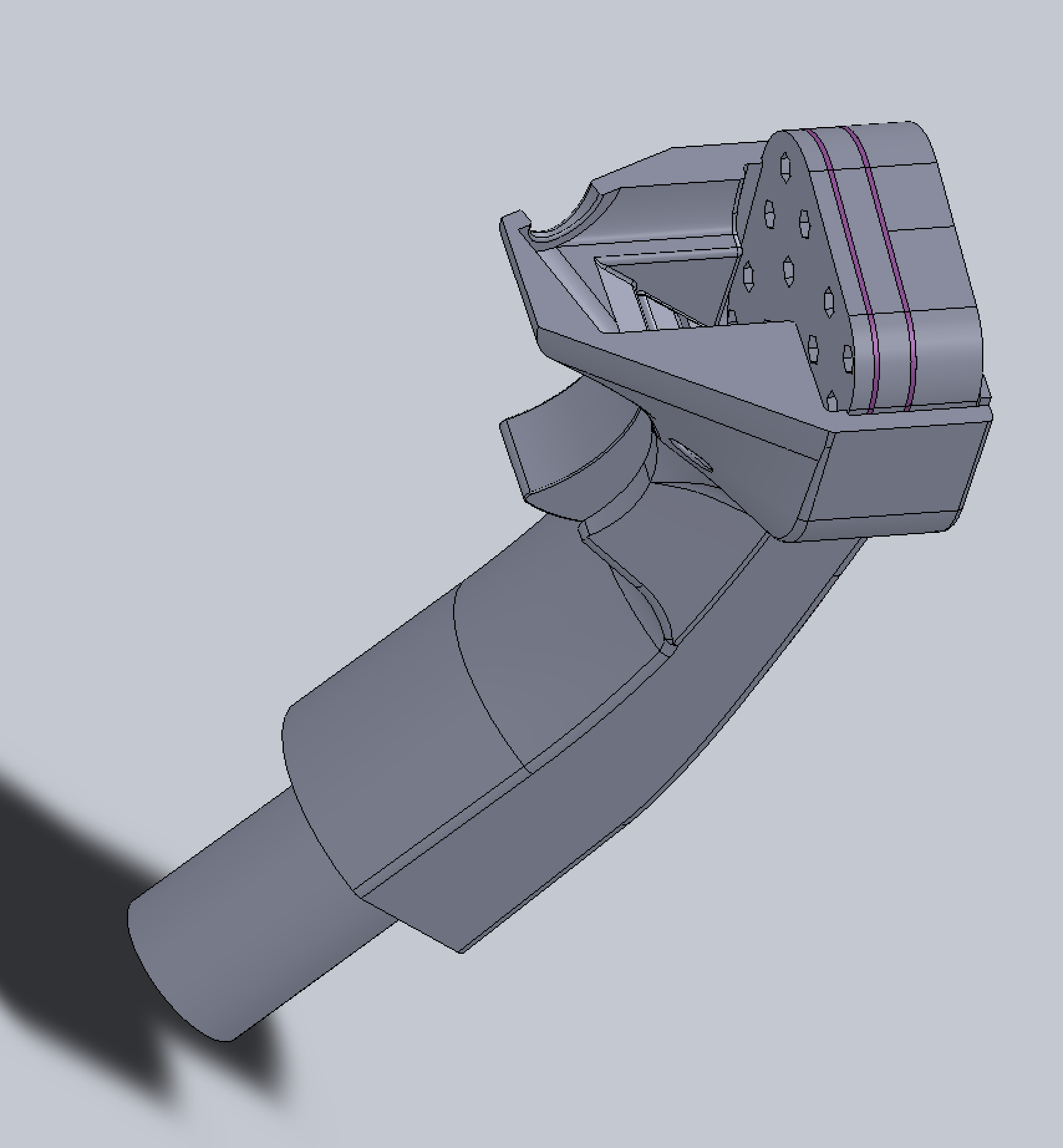
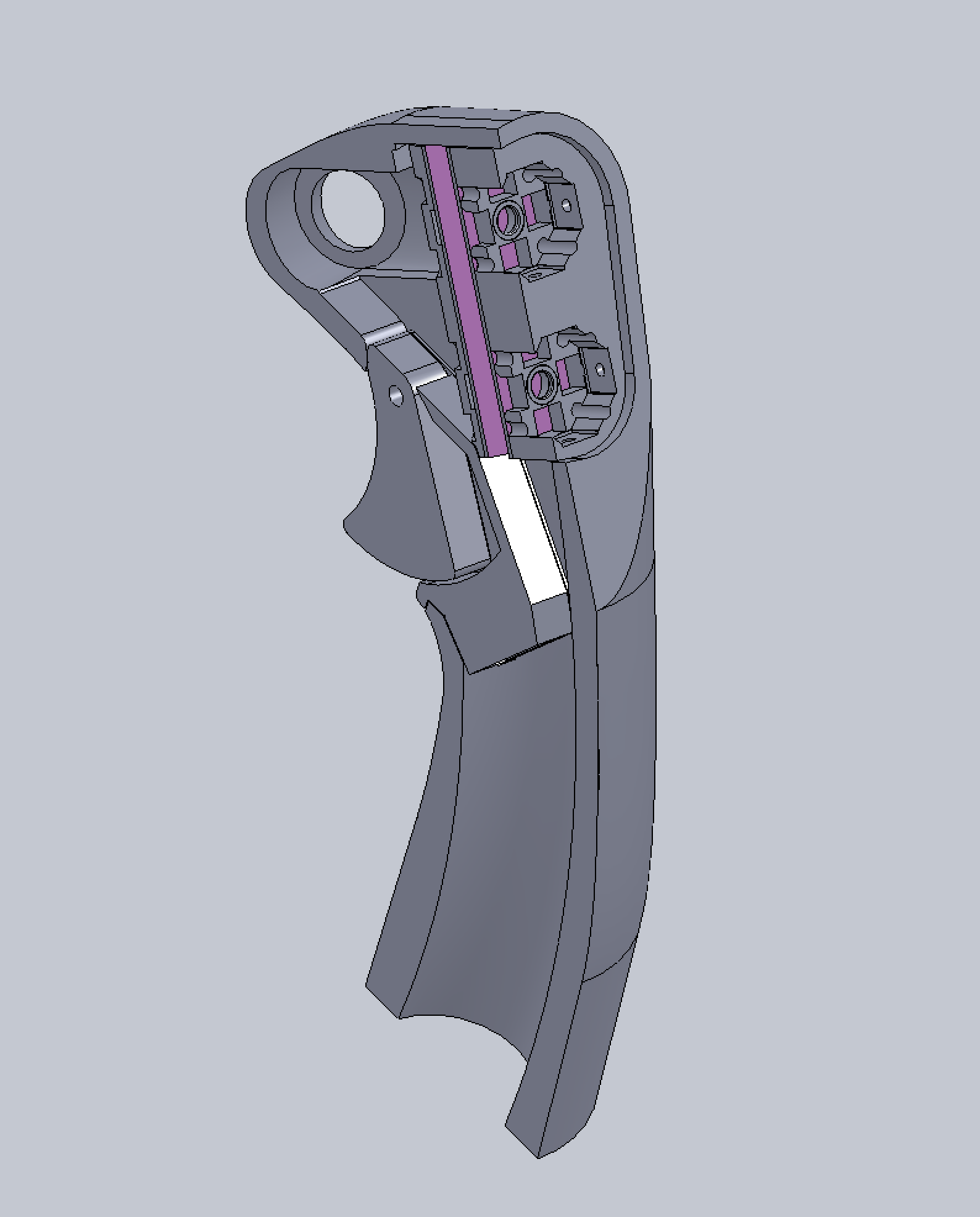
Cut off the top to facilitate Kevlar/glass fiber sleeve vacuum bagging method. I might still cut the front control panel to facilitate easy install. The electronic assembly will have 4 stainless steel shafts protruding out. Might be a bit difficult to wiggle in. From the screenshot here, you can see better the relationships among the electronics assembly, the trigger assembly, and the NWS/MSL Step button. I want my WPN Release button to also be a 4/8-way HAT with pushbutton, instead of those ugly stick on. Now how the "cap" of the WPN REL button is going to look like would be interesting. I am leaning toward something looking like a red WPN REL button, but with texture to facilitate moving in the 4 directions. Also, as you can see, the OD=1" aluminum tube has provision to attach a "hand rest" if you wish. Of course, I still yet to design an adapter/connector to hook it up to the stick base no-gimbal. nullNext thing to tackle, the CMS switch.
-
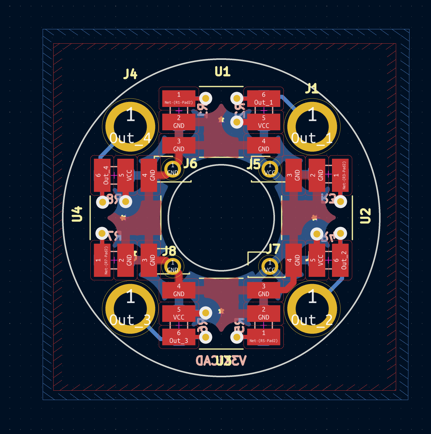
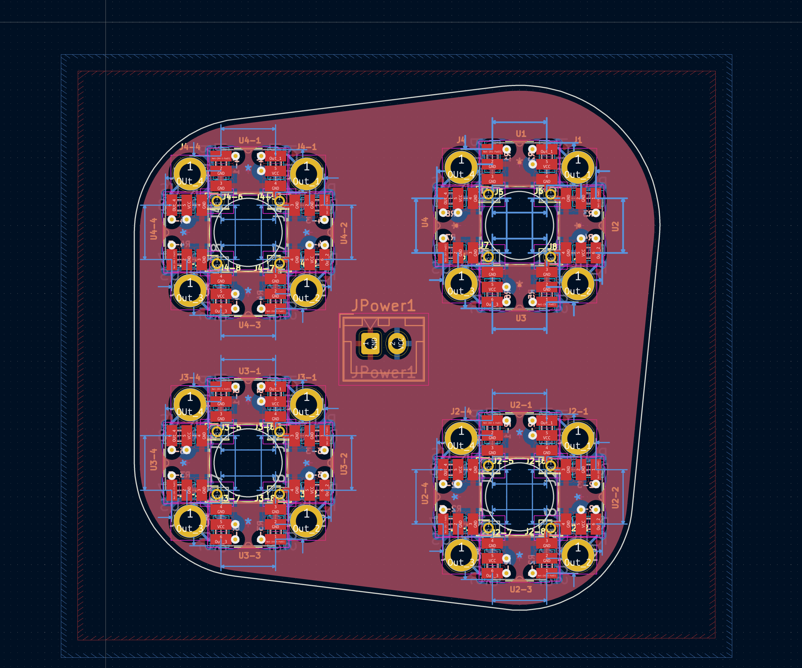
8-way optical PCB. Again, this doubles as the button PCB as well (small cut of a trace). As you might have guessed, this is exactly the same thing the control stick uses. (I imported the layout and replicated it). The F-16 control stick head actually imported the the solid of the outer can of the 8-way 3D model. and merge. So, if that v.11 ever needs to be tweaked, the changes will propagate to the control stick head. No big surprise that this has 4x optical sensors (plus 1 more below for the pushbutton). Again, the trick is figuring out how to synchronize the force feedback (the click) with the interruption of the IR beam. Making work reliably from parts made at hime is the difficult part in the design. Notice that Quest 2's trigger doesn't click? It's actually a magnetic sensor. nullnull
-
This is the optical core for one of the 8-way HAT switch. It's not complete. There are four more machining step to do -- cutting two slits, sawing the two apart, mill off the bottom remnant, and lapping. But this video is the 10x speed video for machining the very core.
-
No dead center, no sticktion, no gimbal. Provision for both spring centering and programmable force generator. It will practically last forever. Well.... that's a lie. But since you will have to make one yourself in order to get one, you certainly can make all the replacement parts to keep it up forever. null
-
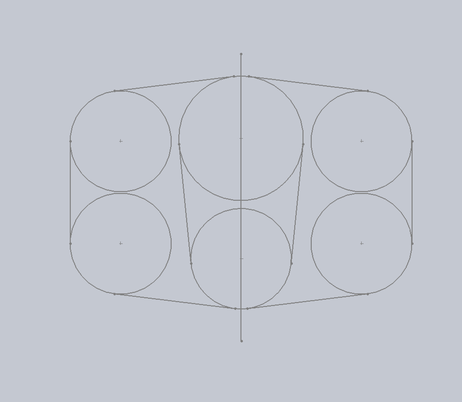
As I said in the title, always Work In Progress. First installment is the "kind of F16 stick." All optical or mostly optical (with provision to use OTTO trigger). This is just the last part of the no-sticktion-no-dead-center force generator stick (NO FFB!). I will post some pictures of the design some other time. The stick 3D form is a bit more angular than the original. The dimensions of the stick body bent part is mostly based on TM Cougar, with the head mostly based on two different A model F16 (a hammer-head stick and a 2 HAT, one WPN release three cluster head, somewhere between the current and the hammer-head). I kind of like the more angular look. With the more angular lines, I can always sand them round. But the opposite is quite a bit more difficult. It is designed from the inside out to integrate 4 clusters of 8-way optical HAT switches (hopefully the CMS will be my own design of optical one, but off-the-shell-part is the backup in case I can't squeeze it in), with two identical PCBs (one for 4 sets of optical cores, each has 4 optical switches, and one PCB for 4 pushbuttons, the OshPark purple ones). So, you can have all 4x 4-8-way HAT plus 4 optical pushbuttons, or just 4x optical pushbuttons. This version (v.11) uses one brass CNC milled integrated optical core per HAT, instead of the v.10 hand cut brass tube sitting on 3D printed housing. The difficulty of optical switches is designing tactile feedback to be in-sync with the optical path interruption, and must have them all sit in an OD=0.75" can, plus a push button, all-in-one. The stick is designed to be 3D printed. Preferably, it's one uni-body without having to split it in two. The central channel is designed to house an OD=1" aluminum or stainless steel bend tube to take up the bending force (epoxy in). Then, the whole thing slide into a Kevlar or woven glass fiber sleeve, and then vacuum bagged. It might be possible to print molds and then use expansion form (high density) to make the "core" and then Kevlar vacuum bagging. However, with the proliferation of cheap resin 3D printers, I don't see why that would be an advantage. Note that, unlike my other website... which posted only 3D models, NOT designs. These here are designs, intended for certain materials, and certain manufacturing methods. For instance, the optical core is intended to be made with a CNC milling machine. Either you get an el 'cheapo CNC router (10 minutes milling), or you buy it from somebody else who makes it for you. Then there is drilling, lapping.... fitting, and calibration etc. etc. Please don't expect anything posted here to be available any time soon (some parts may). I work on my own speed. If I am not happy with some parts of the design, I often leave it in the back of my head until good ideas comes up, often months if not years later. For instance, the optical 8-way has gone through 10 major redesign, over a 3 years period. My intention is to eventually license these designs at very low costs for non-profit home pits, like symbolic $1 per device made or something like that, instead of releasing it in the public for some nation state encouraged thieves to steal them. The PCB design was re-done in KiCAD 6, used to be Eagle 7.x.x. Ok, enough words... from now on, there will be very little words, but mostly pictures in my postings in this thread.
-
Ok... Let me answer some of OP's questions here as well in public, as I think some other people will be interested as well. PTFE is indeed Teflon. But Teflon is a Dupont trade mark... best to avoid using it. PTFE is known as the slickest substance known to wo/men. It has several grades. It's usually a soft material. Very annoying to machine as clamping and machining often distort the material, making precision machining difficult. If you see some white plastic that is really hard, and also very slick, it's usually the other slick substance -- Delrin. Delrin is quite hard, approaching aluminum, but also very slick, a great candidate I also considered but decided against. The PTFE ring dimension is 1/8" thick, OD=64mm, ID=53.5mm. I have no idea what the 40th Anniversary edition Warthog's O-ring size... The ideas of the design of the PTFE ring is as the followings: a). There is a slight relative movement between the rim of the gimbal half ball and the spring piston platform (very slight, but there is about 0.5mm to 1mm movement). b). Due to the slight relative movement, I chose the slickest substance PTFE to reduce the friction. c). The biggest problem with the OOB 2-layer construction of rubber ring is that it's too flexible to hold in position by itself so it was glued down with something like a double-sided tape. This... often got attacked by oil and grease due to "enthusiastic" oiling/greasing. And eventually, the rubber ring got out of position and got pinched and broke (or the thin slick plastic layer simply wore out). d). To resolve #c... the PTFE ring must be stiff enough to hold itself in position without requiring glue or other mechanical fastening. Several experiments like one-side bondable PTFE backed with an aluminum ring etc... showed that eventually, a 1/16" thick solid PTFE ring would suffice. It would be stiff enough to hold itself in that space without any glue or fastener. e). I made it 1/8" thick because the thicker, the stiffer, the more "meat" for wear and tear. At this thickness, it's slightly too thick... so that you lose a bit of extreme deflection of the stick movement. However, after a week or two of use, the PTFE ring will get "pressed" out with a groove, reducing the effective thickness, and you get back your extreme deflection. Therefore, I would recommend that you calibrate when you first install it, and then calibrate it after two weeks of active use. f). Theoretically, since PTFE is the slickest substance known to wo/men, you shouldn't need lube, right? Well... I use PTFE-based grease, SuperLube, which basically is some kind of gel with microscopic PTFE balls... meaning rolling friction is better than sliding friction. it is indeed much more smooth with SuperLube. I disassemble and clean/re-grease about every 500 flight hours. My prototype #0 hand cut PTFE ring since 2011, with 3,000+ hours (if not 4,000+ hrs) on it still look brand new. A lot of Europeans favor Molykote, I don't use that... but what I heard is that it works fine. Basically, you can use grease that is plastic safe. g). The other property about PTFE is that it's very inert. It almost never react with any chemical. It's often used as the coating of magnetic stirrer in beakers in chemical labs. You probably won't have to worry about whether the grease is compatible with PTFE rather whether its compatible with the steel and plastic in the Warthog. Still, I recommend using some plastic and electronic safe grease. Just in case, you know. h). Even though PTFE is soft... it's quite a bit harder than the OOB rubber ring. The rubber ring also causes a buffering cushion effect. So, with a PTFE ring, the stick feels a bit more "snappy" than with a rubber ring. Most people like it, but not everybody. Softer or snappy... does not affect the resolution or accuracy due to the MLX90333 Hall sensor used (if it's a traditional gimbal, this "cushioning" effect would affect your accuracy, very undesirable). The other thing about just getting rid of the rubber ring and run naked. Well.... of course that will work. And a lot of people swear that no wear and tear is observed. Well... knock yourself out. It's not a great engineering practice to let plastic butt against steel with relative movement (small) without a sacrificial/buffering material in between. But, hey, it's your stick. Moreover, it really depends much to the surface roughness of the steel plate in the spring platform. From the two Warthog I have (both pre-ordered), it's made of cold roll steel, usually smoother than hot rolled. But if they change that... or the Chinese OEM factory apply the common 差不多 (about there) mentality and swap the supplier and went for the cheaper hot roll..... YMMV. My recommendation is... don't do it. And if you must, grease the hell out of it. I am not "eager" to sell more, as I view this PTFE ring thing as a community service. I pretty much don't make any money (if I charge you hourly labor rate as a software developer, I certainly lose money on it). So, I am not giving you an ad to advocate buying PTFE rings. I am giving you an honest opinion on best practice in engineering. You make your own judgment, and bear your own consequences. if you want to make the ring yourself... go ahead and knock yourself out. If you still want to order PTFE rings, then drop me a message on this forum. I will send you instruction on how to order. BTW, it's still the same USD $8 apiece. Limit to 2x PTFE rings per Warthog, please.
-
Send me a msg... I still sell laser cut PTFE ring for this problem, as a community service. Still USD $8 apiece; haven't increased the price ever... even though my raw material price and mailing costs have gone up quite a bit. If you prefer to make it yourself... search for PTFE ring in this forum. There is a spec. for making it yourself.
-
Yep…. Or wear an “authentic” surplus G-suit with exactly 1g in something that flies at exactly 0 agl.
-

Warthog: Sticky MIC switch: Replacement info needed.
Hempstead replied to Lange_666's topic in Thrustmaster
Pretty much.... except the CMS on the stick, which is an integrated all-in-one package. The trim is also slightly different, but still 4 mini-button. null -
Why don't you just 3D print it? I know somebody did print the whole HUD unit in parts, and then glue them all together (crazy guy!). As a matter of fact, from your mockup... all you need to print is the part that sticks out. Take my 3D model, slice and dice just the parts you need and slices even more to fit in your 3D printer. nullYou will need a 3D printer these days for pit building anyway. Too much of a good thing to miss, even just for printing knobs.
-
Warthog: Sticky MIC switch: Replacement info needed.
Hempstead replied to Lange_666's topic in Thrustmaster
My apology. The link didn’t seem to go through. hope we we get it through this time. -
You can measure the front panel for it. But the answer is 10 degree.
-
Best not to do conversion to STL. Either use Solidworks files directly, or use other CAD file formats, like Fusion 360, etc. BTW, on the bottom of the HUD, there is a little horizontal “ledge” bump. That bump needs to sit completely out of surface of front panel, like in the attached picture.
-
Warthog: Sticky MIC switch: Replacement info needed.
Hempstead replied to Lange_666's topic in Thrustmaster
Read this thread to get the mini-switch part # posted by Sokol, or buy the whole assembly from TM. -
https://www.hempstick.org/The_Official_Hempstick_Site/F16_Tub.html Then, take the HUD model, https://www.hempstick.org/The_Official_Hempstick_Site/F16_HUD.html, and stick it in. Measure. Done.
-
Quest2 out side world blurry and messy But why . ??
Hempstead replied to KoN's topic in Virtual Reality
No idea... but are you near sighted? If so, wear your prescription glasses, perhaps? You know, just going by your description. -
Steam Deck Verified Playable!
Hempstead replied to A2597's topic in PC Hardware and Related Software
Has anybody gotten this to run? All I got is the DCS splash screen. Any special Launch Options to put in or any specific version of Proton (I tried forcing it to use Proton-experimental, and the latest Proton-7.x.x)? -
A simple solution of cockpit click in VR: Finger-ring touch mouse
Hempstead replied to Jenson's topic in Virtual Reality
The left hand only Monkey On My Back Attachment, after checking the [VR] --> Only when the palm grip ... (or something like that), and turning off the tool tips, is actually quite good. I definitely will give up my slot for Point Ctrl. The need to check the box so it only activates switches when the palm grip is activated is because when the left touch controller is hanging next to the thumb, the virtual finger tips are perilously close to the landing gear switch in F16 when the throttle is advanced to the military power or further. This is particularly bad when doing aerial refueling where you constantly move the throttle forward/backward to adjust your position under the KC135. Well, I never like the finger tip activation thing anyway (hitting my finger tips hard on real world objects are quite painful.). Moreover, even without the attachment, I often accidentally hit some switches around RWR when trying to place the controller in front of my throttle/stick anyway. One additional tip to make this attachment is that you will need to have enough length of webbing for the controller to hang right next to your thumb comfortably. If you don't, you are going to have a lot of trouble trying to get it from your grip to the other side of your thumb. It will only cost you less than USD $17 in material, for two, (less if you 3D print the buckle). Give it a try. -
A simple solution of cockpit click in VR: Finger-ring touch mouse
Hempstead replied to Jenson's topic in Virtual Reality
The real implementation of the Monkey On The Back (of my hands) Oculus Touch Attachment implementation. It's made out of a piece of 3/4" Woven Webbing, and 3/4" plastic clip. Simple. Just two rows of simple bad sewing (two square and a cross sewing is probably what a profession product should have, but that might stiffen the part of the loop that I want flexible.), and a quick twist of stainless steel aviation safety wire to secure the sewn webbing end loop (uses an M2 screw for each loop forming when sewing) to the Touch Controller. That's it. Takes about 20 minutes to make it (I did say bad sewing... here also I am also admitting slow sewing). The make and usage needs a bit of a reminder. 1. You must have a bit of the webbing "hanging" length between the plastic clip and the loop end, otherwise you can't "swing" it clear your thumb and allow it to have the length to wrap around your thumb and hang there naturally by gravity. If you leave not enough length, it will twist and "strangle" your thumb, making it very uncomfortable. 2. You should "flick" the controller on/off by lifting your elbow up and hand down using the gravity to clear the handle part of the controller to clear your thumb. A bit of a coordinated "swing" of the elbow... otherwise, the handle part can get knocked around by your thumb and get tangled up. Don't use 1" webbing... thinking that the wider it is, the less it will get rotated. 1" is too wide for the space between your thumb and the root of the index finger, making it very uncomfortable. 3/4" is about the widest for my Large hand (measured for gloves). I hereby declare this design of mine in the public domain. Do whatever you wish with it. Attribution will be appreciated, but not required. Apology for the very unprofessional abrupt end of the video... I ain't no professional in this anyway. Edit: Note that you may or may not want to do the right hand attachment. Because, the movement of the right stick tend to trigger the Touch Controller bleeping/vibrating to signal you that it has just been activated. It's very distracting to me when I am doing aerial refueling, the right controller constantly nagged me for nothing. I mostly use the right hand controller for cold start and pretty much everything on the ground, but in the air, I tend to use left hand controller for pretty much everything. I did implement the right hand attachment as well for the sake of symmetry, but does not strap it on when flying, instead I place it in front of the stick as it was. -
ExpressPCB advice sought for non rectangular boards
Hempstead replied to lesthegrngo's topic in Home Cockpits
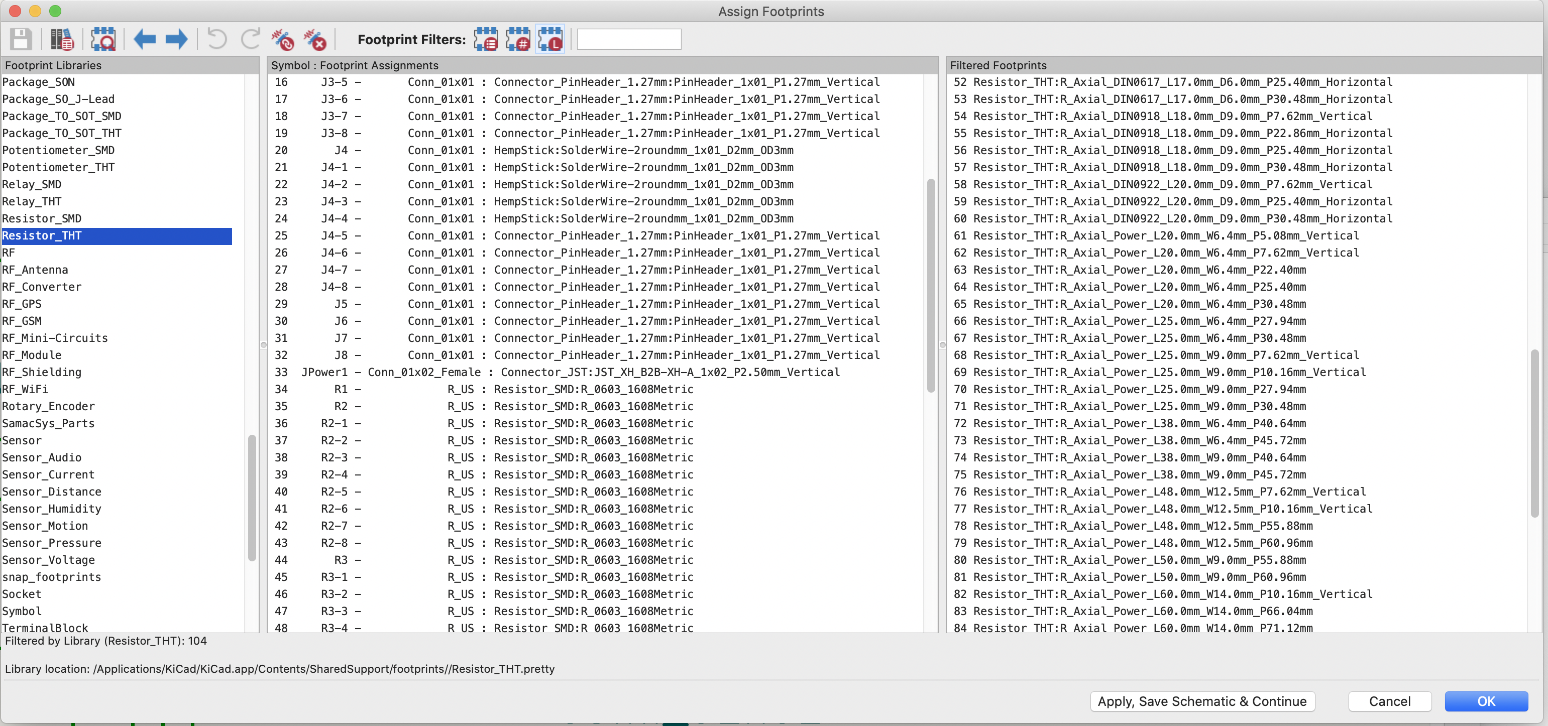
Ah... that problem. It's very annoyingly flexible, too flexible and over designed IMHO. Ok... here's the deal. KiCad has a very large document on parts/packages naming convention, officially called KiCAD Library Convention (KLC), here, https://klc.kicad.org/#:~:text=G1.,%2C a-z %2C 0-9 ). It's like it's designed by a very large committee to piss off everybody. It's called European Consensus, or a Camel (a horse designed by a committee). KiCAD differs from most other EDA software in that the parts in schematic do not specify (usually not, but could) the package/footprint. Ya, so they decoupled symbols and footprints. Yay... modularization! So, a resistor, is just an R, doesn't say if it's SMD or THT, nor the size. Unlike in Eagle, for example, you select an R-0603 in schematics. But KiCAD gives you the flexibility so that you could have one schematic with many different boards that allow you to use different packages in each component in each board for each of the possible combinatoric explosion that you would never ever need, theoretically. But in practice that rarely happened. And they implemented it with, by default, one schematics with one board anyway. Yes, sometimes it's nice to be able to say, oh... I can't source this part, so I can just replace the footprint with another part, and create a different board so when the first part came in stock I can just switch back to using the original board, particularly in these Pandemic days that a lot of chips are unavailable. But, you'd have to jump through some little hoops to get multiple boards out of one schematics. Not too bad, it's quite doable. Because of this, you'd be adding something like a generic SW_DPST. And then, you'd have to go to the footprint assignment tool to choose what footprint to use for it. Ah... and the confusion of the long names begin! I find this process very exhausting and error prone, not to mention those footprints all have very ridiculous long names, per the KLC. One little character read wrong and you end up with something very different from what you want. Don't believe me? Ok... find me the footprint of a common garden variety 1/8W through hole resistor, see the attached screenshot. And note the size of the scroll bar, as you are only seeing a small portion of the footprints in there. Thank goodness SMD resistor footprints names are much easier to decode. But fear not... the "committee" considered that... so you could just download some symbols that have their footprint specified. See... a camel can also do everything a horse can do, just not as well. And, with these "pre-ordained" symbols, you can still change the underlying footprints if you want! Best of the both worlds! Why didn't they just do that to begin with!!!??? *@&#^%@ It’s just that, if you do that, the symbol name and the footprint differ might cause some real confusion. So, what I find easier to do is to first download the Digikey library (GitHub) and install it. While you are at it, grab the Sparkfun library, and Adafruite library as well. It has a lot of common parts DigiKey sells, and foot prints are associated with the the symbols. This alleviate a lot of "that" problem. The next thing to do is every single part you have you will eventually need to nail down which exact part # to buy, so you could actually go to Digikey or Mouser and download their part symbols/footprints. Mouser uses Samacsys in the back, which requires you to download a Windows version of software called Library Loader and install it in order to search and download symbols and footprints. Technically, they have add-on/plugin so you can do the search/download from Samacsys in the EDA, like Eagle, but I have never been able to get it work right. Snapeda, UltraLibrarians (DigiKey uses this) are also two other good sources. Smacsys will even create symbols for you in a very timely manner if they don't have it and you request it on their website (my past experience is that I got the new symbols created the next working day, and no charge; YMMV). Short of that, you can always create your own symbols and footprints... it's an essential skill to learn anyway. It's not bad. KiCAD is actually quite alright in this. Moreover, with all those long and confusing names... for simple parts, it's often faster to just create the damned symbol and footprint than sifting through the large # of footprints that are very lacking in detailed description. Surely they have a pad for M2 screws! I ended up creating my own after a long frustrating search. Good luck!
-
A simple solution of cockpit click in VR: Finger-ring touch mouse
Hempstead replied to Jenson's topic in Virtual Reality
That is not what the attachment scheme is supposed to solve. I am not using the Touch Controllers to replace my Warthog stick. I am using the Touch Controller as my hands to flip switches and dials, as designed by ED. Like I said, The attachment is only supposed to solve the problem of having to reach out to grab and fumble the Touch Controllers placed right next to my Warthog before I can use them to flip switches and dials, and for selecting comm options instead of pressing the F* keys. Moreover, this thread is about using a mouse ring as your hand to flip switches and dials in VR. What I was saying is… I don’t need a mouse ring to flip switches and dials. I use this attachment scheme to help me flip switches and dials with the Touch Controllers. Viper1970 is saying he uses two trackballs mounted in the pit to flip switches and dials. I considered trackballs as an option, but didn’t like the idea, because I will still need to reach out and fumble with my hands on the trackballs. I suppose with practice, one can minimized the fumbling and be proficient with trackballs. It’s really down to personal taste. There is no right or wrong answer here. -
A simple solution of cockpit click in VR: Finger-ring touch mouse
Hempstead replied to Jenson's topic in Virtual Reality
Here's another test. The difference between this one and the previous one is simply the way the lanyard is "routed." This one proves that a glove is not needed. A bit creative "routing" of the lanyard is sufficient. However, it also demonstrated that the lanyard needs to be longer and have two locking slides. Perhaps Velcro? Perhaps some more comfortable cloth tapes, ropes, whatever, and some finishing touches instead of just a twist tie. Edit: Actually, a lady’s bra strap would probably do well instead of the lanyard. But I think I can do better with some cotton woven twill tapes and 3D printed buckles. -
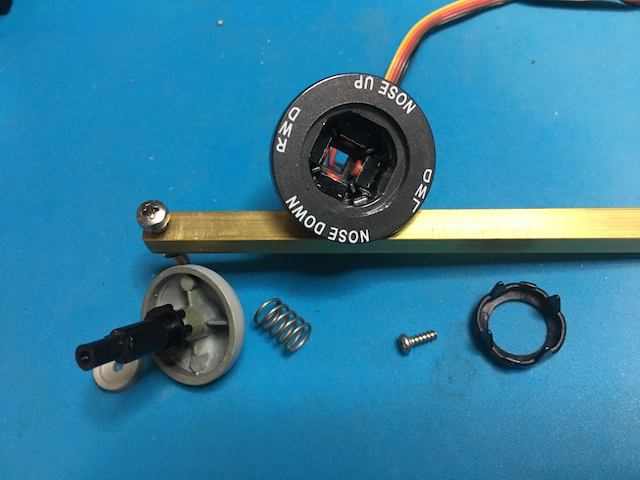
Yes... I did replaced the whole trim, bought from TM -- the only source for it. So, either you buy the whole thing from TM, or you replace the mini-pushbuttons inside. My all optical replacement of my own design... is not for sale. But you don't really need to replace the whole thing unless the shaft or the case is broken. If it's just the switches/buttons... nullViper trim switch internally has the same design as throttle's MIC switch and other HAT switches -- 4 mini pushbuttons in each direction, see attached picture. The only difference is that it does not have the down push provision. So, its casing design is a one piece instead of 3 pieces. Please refer to this thread, where Sokol provided the exact part # for replacement of the mini-pushbutton. You will need to solder the wires though.