
nighthawk2174
-
Posts
1517 -
Joined
-
Last visited
Content Type
Profiles
Forums
Events
Everything posted by nighthawk2174
-
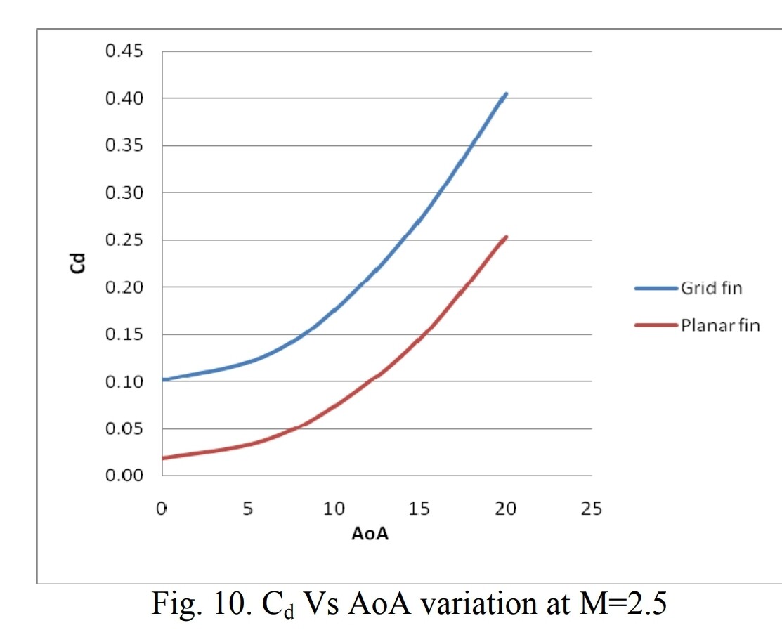
ADA509444.pdf Is a publically availble doc that has data up to M5.0 with more information, its results agree with the one I posted and is a source of wind tunnel data used by other reports. What assumptions on deflection angles did it make that you are questioning? Traditional fins will need larger deflections but at the same time their far more efficent with those deflections and have less 0 aoa drag. The biggest thing is the reduction in hinge moment per unit of aoa you want to get too, that is where the lattice has its largest advantage over a planar fin. Just as an example lets say the missile needs to generate 300 lbs of lift per fin at M2.5 for whatever manuver it will be doing at that moment (I assumed 1000ft at STP for aero values). This would be what i'd probably clasify a "light-medium" correction considering you'd get thousands of lbs of angular force from all 4 fins. Using the data in the first report to generate 300lbs of lift the lattice fin will be at ~0.7-1.1deg aoa and the planar at ~3.8-4.2deg. At those angles the gridfin will generate nearly 15x the drag (60lbs vs 805lbs) or a L/D of 5.0 vs 0.38. Keep in mind this is also with a very suboptimal planar fin design used in the study. This drag penatly is why these types of fins are not in use for A/A missiles anymore. They make a lot more sense on ballistic missiles or bombs. Where the low hinge moments are very usefull and the drag penalty not as big a concern. In the paper I listed newer shapes of the lattice that were tested can cut the drag from 25-40% depending on mach and exact shape but the R77's fins are not one of these and even then planar fins still have better L/D.
-
Yes however at the cost of drag especially in the M0.7-M2.5 region. Ultimantly thrust vectoring is a far more appealing solution without really any downsides apart from complexity. 1 - It can but often at the cost of high fuel consumption. 2 - True but chocked flow still persist even past the transonic its not until the shocks are at a low enough angle they do not interact till well aft of the lattice that flow becomes unchocked. 3 - Even then you will generally still have more drag when comparing similarly sized fins, based on actual dimensions not reference area, due to higher area. Even at higher mach regimes their drag coefficients do leave something to be desired when compared to monoplane.
-
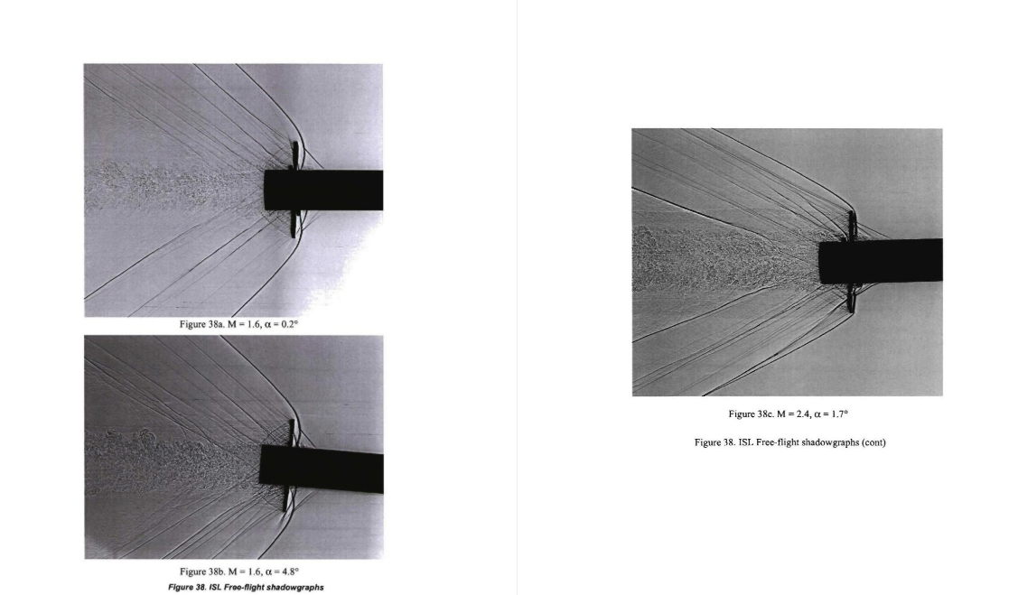
No this study is perfecly valid you're just coping. The study is practical in that it compares two similarly sized fins. If you were to make the monoplane fin have the same reference area as the lattice it would be impractically large. Even then the advantages of the monoplane in L/D and static stability would still persist. Just fundamentally the lattice will have higher drag then a similarly sized monoplane fin due to shock interactions especially at lower mach numbers. This persists up to ~M3.5+ when the shock interactions occur aft of the lattice instead of inside the lattice cells. There is no getting around this whether or not your comparing two similarly sized fins or two that have the same reference area. Below the blunt shock ahead of the lattice is a clear indication of chocked flow and is why there is a dramatic increase in drag coefficent. NOTE the above is NOT my work I just coppied it from another forum where this exact same disscusion happened. You can calculate this point yourself if you want just lookup the oblique shock tables or follow this: 19930091059.pdf These studies help prove my point I wish I still had access as I did a few years ago but if your willing to pay they prove my point: Subsonic/transonic free-flight tests of a generic missile with grid fins | Aerospace Sciences Meetings Subsonic Flow CFD Investigation of Canard-Controlled Missile with Planar and Grid Fins | Aerospace Sciences Meetings

-
This is a well-known limitation of lattice fins; it doesn't matter what you believe lattice fins are a not some big unkown. The data comes from a publicly available report. There's a reason no one is using lattice fins on their latest missiles anymore not the Europeans, Americans, Chinese, Japanese, Koreans, etc. The improvements you could possibly get, you can achieve more effectively without the downsides by using thrust vectoring. ANALYSIS OF GRID FINS AS EFFICIENT CONTROL SURFACE IN COMPARISON TO CONVENTIONAL PLANAR FINS
-
Dynamic pressure is usefull for viewing shocks as the pressure drop post shock is rather quite easy to see. The CFD results point to why lattice fins tend to really only come into their own at very high mach numbers. the shocks are still at a relativly low angle and are interacting well inside the lattice structure. Resulting in chocked flow aka higher drag. For CFD the amount of time it takes can wildly vary. It depends on how accurate you want to be. More accurate you need a higher quiality 3D model, denser mesh, and more data points simulated. It can range from days of work to months. To build out enough data points with a reasonable model/mesh for a proper FM I'd lean towards longer rather then shorter. The software itself will pretty much give you those axial force coeficents and with some work the center of pressure can be found as well, you can often calculate these for individual components rather easily as well. With said components a flight model can be built.
-
Go ahead
-
Both
-
May be relevant
-
Мне интересно, как вы это моделируете? Я бы хотел узнать, как это делается.
-

correct as-is F-16 Look-Up Detection from low altitude
nighthawk2174 replied to Star57's topic in Bugs and Problems
The APG-68 also has sidelobe guard horns to suppress the sidelobe clutter as well. Is that even considered in this model? -
AIM-54 Hotfix PSA and Feedback Thread - Guided Discussion
nighthawk2174 replied to IronMike's topic in DCS: F-14A & B
Does the AIM-54 use the APN stuff that ED added? -
reported Aim120 can not see targets against the sky
nighthawk2174 replied to Hobel's topic in Weapon Bugs
Yeah and this is just how feedback loops can work in general. I fully agree with your inital post as the target would not have to compete against clutter and would stick out. So when the speed and range gates are run through the return spectrum they should just grab the target. Lookdown would be harder but still possible for MPRF, HPRF would rely entirely on S/N being high enough. -
I think this also applies to ATGM's which is a big issue for the apache.
-
need track replay Is the sparrow affected by flares and chaff?
nighthawk2174 replied to Indianajon's topic in Weapon Bugs
The spparow's also home in on doppler, they track using a speedgate. This should provide good resistance against chaff considering how quickly they loose speed. -
Yeah this is what English bias commands are for, from the AIM-7E autopilot diagram I have the english bias commands are applied at the moment of wing unlock which occurs even before seeker lock on. It seems like that's not happening here super odd. Almost as if their reversed???
-
F-16 vs. JF-17 radar & BVR performance test flights
nighthawk2174 replied to Aquorys's topic in Weapon Bugs
Never heard of it having hprf, it’s a mprf radar. It does have a lprf mode. -
F-16 vs. JF-17 radar & BVR performance test flights
nighthawk2174 replied to Aquorys's topic in Weapon Bugs
Note that the Jeff has HPRF which has better detection range. -
investigating AIM-120 still can not chase simple Split S manuever.
nighthawk2174 replied to opps's topic in Weapon Bugs
The issue here is that in MPRF when you feed the returns into the associated apparent range bins then feed that into the attached doppler bins a good portion of that clutter will fall into another doppler bin whereas the target will be in one range bin. This will reduce the amount of energy that the target return has to compete against to whatever happens to fall into the same doppler bin. The MLC is not all at the same doppler as the target and the larger the look angle and the larger the velocity of the missile the more that energy is distributed. Were in STT not search as well, currently it seems that the notch is 100kts'ish hopefully you can give the exact number. But In STT your tracking gates are going to be much much smaller then this. Typical values I see referenced are 15m/s in total width. And the missile should really only loose the tracking gate if the target is not competing with clutter. But that would mean that you could get a lot closer to the central MLC return (especially at close range and for high RCS say being side on or given your belly to the target) without loosing track. If not right on it if the noise is low such as in only very low look angles or low return clutter like calm seas. Also we can't ignore factors like integration time and PDI for S/N.
-
reported Aim120 can not see targets against the sky
nighthawk2174 replied to Hobel's topic in Weapon Bugs
Yeah seems this is part of the notch behavior discussed before: my thoughts on the matter are layed out in this thread. -
correct as is DCS Aim-7 Sparrow Potentially Underperforming
nighthawk2174 replied to DCS FIGHTER PILOT's topic in Weapon Bugs
I'd seen some documents reference two different nose cons for the 7F one that is better for the sensor and one better for aero performance i'd just never seen the difference. Do we know which one was in more common use? edit: Didn't the 7M get another redesigned nose again from the 7F? From just one quick image grab it seems that it's closer in shape to the older but more aerodynamic nose cone: -
There will be at some point it will be able to go active on its own. Currently the only benefit is better chaff resistance.
-
investigating AIM-120 still can not chase simple Split S manuever.
nighthawk2174 replied to opps's topic in Weapon Bugs
The AIM-120 has an INS so by default its going to know the targets location in 3D space. You could easily look for a split S based off of this information. We know from documentation that there is a method by which there are adjustments made to compensate for the split-S on the AIM-7. I highly doubt the amraam would not have something similar if not even better. -
investigating AIM-120 still can not chase simple Split S manuever.
nighthawk2174 replied to opps's topic in Weapon Bugs
According to razbam's galinette DCS was only returning a constant value for the RCS even when side on. I linked him to your post and I think he said he was going to talk to you. Are you sure this is implemented? -
investigating AIM-120 still can not chase simple Split S manuever.
nighthawk2174 replied to opps's topic in Weapon Bugs
Yeah i'm still a little fuzzy on this but don't rage bins come before the Doppler filters? -
investigating AIM-120 still can not chase simple Split S manuever.
nighthawk2174 replied to opps's topic in Weapon Bugs
Part of what's going on here too, aside from mprf stuff as i'm not quite up far enough in my reading to know the exact answer I know it can be done though. We can't ignore S/N either, i've seen missiles notched at less then two miles. Except that there's a ton of things that should make the target compete even against a large MLC. The STT nature of the track ensures that integration time is extremely high effectively infinite, monopulse itself also has S/N benefits, side on RCS will be huge as well, the employment of PDI will also help. The type of terrain would also be important: https://patents.google.com/patent/US4559537 method of tracking targets in MLC patented by Raytheon in 1985 right when AIM-120 development was in full swing. Also from earlier are you using 15deg for the beamwidth for the amraam? That's huge way beyond a reasonable value. MACE uses a value of ~3-4deg Edit: The video posted by Vatikus is exactly how you deal with mprf ambiguities i'm still working on understanding the exact mechanisms behind mprf but as shown in the vid it can be done easily. There's a reason MPRF is so widly used.