yogi149
-
Posts
376 -
Joined
-
Last visited
Content Type
Profiles
Forums
Events
Everything posted by yogi149
-
Hi Nimo, von wem denn?
-
 Hi Winghunter yes, I thought, that you want use only resistor for the LED current. But if you want more than 100 hours of livecycle for the LED panel, you should use LED-sources with constant current. In your circuit the LED current changes with every activated LED. And normally LED driven in that manner last only 50-100 hours. I know that because we used some RC-light modules for static models, which drove customers angry when LED died after some hours. Best for LED are pulsed power sources. (Take some videos from modern cars LED-backlights, you will see them flicker) It may be wireless on the PC side, but the wiring of the LED image and the image interpreter will not be easy, and certainly no less work than individual USB boards. And why do you talk about Arduino boards, when there are BBI boards, that handle switch as input and work as joystick for the simulator. My experience with cockpit makers: they want something that is plug and play. And as easy to use as possible. And let's be honest, who wants to wire tens of thousands of switches and assign them in the simulator. For playing with an image interpreter it is certainly a nice idea, but I don't see a replacement for the existing solutions. And I wish you that you will reach your goal with it.
 -
So Winghunter, somehow I have a problem with understanding here. You want switches on panels to switch LEDs, which you then identify with a camera in order to switch inputs in the simulator. To do this, you have to control the LEDs using switches and a regulated current. Preferably with constant current sources. Then you have to put that on a circuit board, when you can simply connect or solder a switch. It's not an LED matrix. With the planned number of inputs, it will be a huge circuit board and a huge pile of cables. A transmission with an optical status table is a nice idea, but where exactly is the simplification? There are different bus systems such as I2C or CAN bus for more inputs. Even USB with named boards is easier to manage. And scanning at 60Hz is unnecessarily fast for switch panels. I myself took the Arduino mini with I2C bus 5 years ago to control instrument replicas, all with a mega as a central computer connected to the simulator via Ethernet.
-
Hi, I may be a lousy pug now, but if you swap the "Gear" panel for a "Floats" panel, which now has 3 more switches, you have to swap the whole section in your interpreter. The effort 1. to wire the panel so that the appropriate LEDs light up and then 2. to adapt the interpreter so that the right section is also available in the simulator is now higher for me than connecting a single panel with a USB controller. Or am I wrong? I still don't see the minor effort to wire the switches for the LEDs appropriately instead of using inputs directly. Apart from that, given the number of LEDs provided, the LED image is also a very high expense for the circuit board and the power supply. Troubleshooting should be relatively difficult.
-
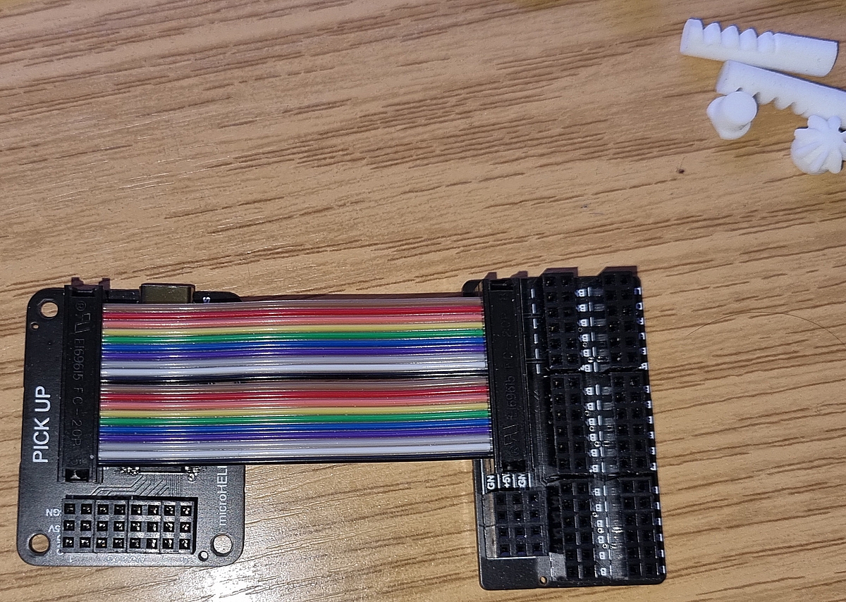
Hi, the 64 and a 128 type were also planned, but have been postponed for the time being due to a lack of available microcontrollers. What do you mean with flatband cables? Should go, because the distance for the pins is 2,54 to 2,54 mm (as usual for my controller) first 6 wire transfer the axis 1-4 to my spreadout board, 7+8 could be empty but complete 20 pole is easier to connect. For my collectives I use 18x0,14 shielded industrial cable to connect the control-stick with 1 connector.

-
Hi, are you sure, that DCS can handle that amount of input you try to realise? And can you tell me, how this unusual concept can minimize the wiring work? You have to connect your sections to the LED cluster, as before to any BBI (button-box-interface). Than you have to make an interpreter for the LED-cluster image, which would need a standalone CPU-unit. And you have to attach every interpreted input to a DCS function by selecting it from "one" input device. If you change a section, how can you identify the changed inputs? Nice idea, but I think that the work to get this running is much higher, than to stack some USB BBI and connect them to DCS. But with this idea I finally know why WOPR (wargames) had so many lights.
-
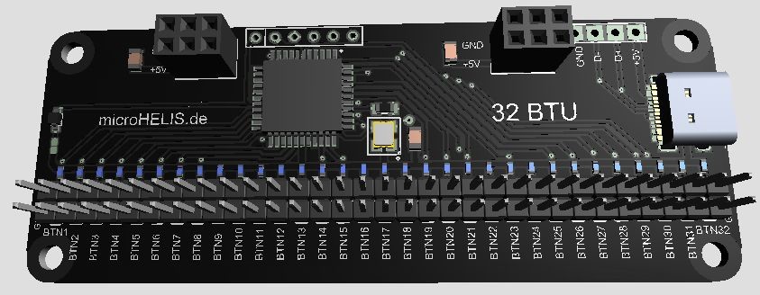
Hi, yes, they are powered by the USB. And they have an addtional 5V on the board, so you can use switches with LED/lamp too.
-
Hi, ähm, 16 boards (0 -15) can be identified by the ID. So even 32x16 = 512 inputs can be used. But I don't know how many inputs DCS can manage. Boards with 64 or 128 inputs are being planned, but Windows will only ever display the first 32 inputs.
-
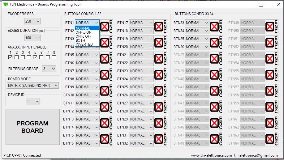
Hi, yes, USB-C type connector. With the programming tool, you can configure every single input in the shown way. The programmable device ID is from 0-15, as with my joystick contoller.
-
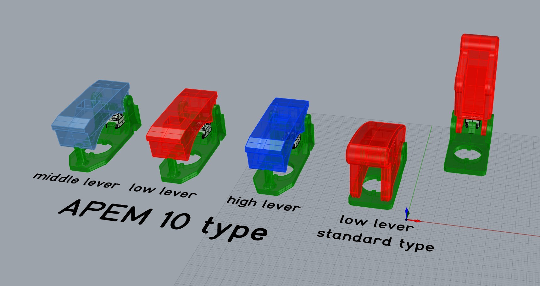
Hi, regardless of the fact that DCS does it now, I've expanded the types. The guards are all constructed in such a way that they force the switches into the indicated position when they close. As usual with the original. In the open position, the guard actuates a microswitch that can be integrated as a signal. This means that the switch can be in all positions, whereas when the guard is closed, the switch is forced to be in the correct position. These are the 32 button boards that I'll be using soon. The inputs can be programmed for different functions. You will get an additional board that enables the connection of the buttons or switches with screw terminals. A 12-position switch with 2 wires will then also be possible. And 5V for illuminated switches are also available. regards yogi
-
Hi No1sonuk, the next time I remodel my RIG, I will use my own controller boards, these have some additional features compared to the Bodnar BBI and BU boards. The new controllers can output the activation or deactivation or both of a switch in corresponding functions. I don't need a LUA anymore.
-
Hello, before such an unpleasant mood arises here, perhaps the demands of the pit builders should be clear. I came up with the solution because I am using a combination of physical pit with VR. In VR it is helpful if I can see the guard position. I make replicas of the controls so the switches and buttons are where I see them in VR. I don't want to think about which function I have now assigned to which key and where is it now. I built a GNS430 dummy so that I can operate the navigation device under my VR glasses without having to twist my hands with the controllers. And ultimately it just looks nice when the switch protection moves in VR when I move the part. And I need some LUA too, because I use the physical correct ON / OFF switches, so I have to assign both functions to the physical behavior of buttons and switches And DCS is definitely not the only simulator that uses this function in the display.
-
Hi Nikolas_A, but you are free to tell how you would move the guard in the 3D/2D cockpit. (without mouse or controller) I use this function to increase my imersion with switches and buttons on the right places. And some of these guards show essential functions in the cockpit with only one view. regards yogi
-
Hi, I made another type of switched cover: regards yogi
-
Hi, I use a micro-push-button to detect the open cover.
-
Hi, ist zwar von 2013, und damit eigentlich immer noch nicht verifiziert für die aktuelle Version. Aber auch von meinem Empfinden her, wäre dann ein 128er Modul eine sinnvolle maximal Größe. Das ist ja auch vom Verkabeln her schon sportlich.
-
lass doch die Achsen weg, dafür habe ich ja was brauchbares. Für die meisten Flieger kommt man doch mit 8 Achsen hin. Für die Pedale habe ich ein kleines 3-Achs Modul, das braucht keine weiteren Eingänge. Ich würde die Boards lieber einzeln anschliessen, damit man die Boards im Sim besser zuordnen kann. Für mein GNS430 braucht es ohne Display 23 Eingänge, wobei da 6 Encoder drauf hängen. Da wäre doch ein kleines Modul, was dann direkt mit USB an den PC oder USB-Hub geht, sinnvoll. und damit wäre wir schon wieder bei der Anfangsfrage, wieviele Eingänge verträgt DCS überhaupt? Und das bitte ohne Keymapping!
-
Hi Viper, es geht doch genau darum ein "Bastellösung" zu vermeiden. Es gibt haufenweise Leute die eben genauso etwas nicht wollen. Die wollen ein Bord haben, was einfach ansteckbar ist und einfach zu bedienen. Die wollen nicht irgendwelche Schaltfunktionen auf kryptische Buchstaben legen, um dann im Sim diese wieder einer Funktion zuzuordnen. Die wollen eine Funktion aussuchen, den zugehörigen Schalter betätigen und nur noch bestätigen. Das DCS da nicht ganz mitspielt verkompliziert es ja nur. Keymapper gibt es einige. Aber das kann es doch nicht sein. Bei dem anderen Sim, denn ich sonst noch so benutze, kann man die für die Belegung von ON/OFF nötige LUA mit dem Stick mitgeben, dann ist sowas für einen potentiellen Kunden extrem einfach. Bei DCS müsste ich mich mal in die LUAs einarbeiten, komme bloß nicht dazu.
-
Hi, nö, geht wirklich nur um ein einfach konfigurier- und ansteckbares Eingabe Board. Plug & Play Sticks habe ich ja. Und auch der Indianer ist kein Problem. Geht wirklich um größere Panels. Deswegen ja auch die Frage: wieviel Eingänge braucht es wirklich?
-
Hi Viper, hast Recht es sind 126 Seiten. Deine geliebten PoKeys haben regulär nutzbar 54 Eingänge, die man auch Keyboard Eingaben zuordnen kann. Sie haben noch einige Funktionen mehr, die man aber so nicht im DCS nutzen kann. Wie Du selber in einem anderen Thread von 2019 feststellen musstest. Also geht es mir immer noch um ein direkt verwendbares Board, was erst einmal nur Eingänge verarbeitet. Arcaze macht soweit ich weiß nichts mehr, und war vor 3 Jahren auch nicht zu einer Zusammenarbeit bereit. PoKeys sind eigentlich CNC Steuerkarten, die nebenbei auch für FluSis mißbraucht werden. Bodnar passt seine Bediensoftware (die eigentlich von Logitech aus dem Jahr 2004 stammt) nicht an. Die Controller könnten eigentlich mehr. tja und nu? Die Frage, die immer noch im Raum steht: wie soll so ein Board aussehen? Und man kann auch mehrere Boards benutzen. Mein 1. Pit war eine EC-120, die mit mehreren Arduino Mega über Ethernet mit dem Sim geplaudert hat und meine Hardware Rundinstrumente wurden über I2C Bus angehängt. VEMD und Kartenmonitor gingen über Android.
-
Hi Viper, also eine ca. 130 Seiten Anleitung ist definitiv nicht als easy zu bezeichnen. muss man wohl, weil das Ding eine Batterie zur Speichererhaltung hat. NO-GO für mich. Ein Arduino vergißt da eher nix. Hast Du tatsächlich schon mal eine 16x8 Matrix verschaltet? Da muss doch zusätzlich noch jeder Eingang eine Diode haben, sonst kann man nämlich innerhalb einer Reihe keine 2 Funktionen gleichzeitig belegen. Deswegen gibt es ja z.B. mein Spread-out und das Bodnar Matrix Board mit den 6er Blöcken, da sind die Dioden am Board. Und die Software vom Pick-up Controller läßt auch die Definition für gedrückt und losgelassen zu. Für jeden der Eingänge auswählbar. Mir schwebt halt erst einmal ein 128 Eingänge Board vor, das seine Identität im Windows nicht verliert. Damit ist nämlich schon einiges gewonnen. Wenn möglich nix "programmieren" sondern nur "definieren".
-
Hi, und schon wieder die Keyboard Funktion, jetzt allerdings noch mit Programmieraufwand verbunden. Ja, die Boards können schon einiges, aber doch eher für die Hardcore Pit-Bauer. (Aber das kann ich dann auch mit einem Arduino Mega für die Hälfte vom Preis.) Das ist doch nix für mal schnell zuweisen, was ich mir vorstelle. Ausgänge ja, aber wie teilt DCS das dem Board mit? Gibt es denn passende Ausgabe-Funktionen direkt im DCS? Womit wir wieder beim Open-BIOS gelandet wären.....
-
Hi, eigentlich nicht. Da ist leider die "Intelligenz" von DCS gefragt. Das geht über eine LUA, mit der eben quasi die Leitung abgefragt wird. Gedrückt = ON und wenn nicht gedrückt ist diese Leitung eben aus = OFF. Das geht doch jetzt auch, und mache ich auch immer, weil ich die physikalisch korrekten Schalter einbaue, das spart einiges an Leitungen. Zum Keyboard: nur schwenken ist doch zu "trivial", mir schwebt eine Gleit und Drehbewegung vor, bei der ich die Tastatur mit einer Handbewegung von der Seitenposition direkt vor mich bringe. In etwa so wie sich beim Pkw manche Motorhauben oder Kofferraumdeckel bewegen. Aber zeigt mal eure Lösungen, eigentlich bin ich immer neugierig.
-
für meine aktuellen Boards stehen 15 Namen für jeden Typ zur Verfügung. Deswegen ja die Frage, ob sich z.B. 128er BBIs lohnen würden. ein Actuator Bord z.B. für circuit-Breaker ist schon in Planung.
-
Hi, weil links noch was hinkommt. Und die Tastatur aktuell auf dem rechten Knie benutzt wird. (ohne VR) Wenn ich da eine Schwenkmechanik mache (die mir ja schon ein paar tage im Kopf rumgeistert), ginge die auch für links, und wird hier zum Nachbau gezeigt. hm, schreibt ihr jetzt ja nicht zum ersten Mal, aber wieviele "Eingabe" Möglichkeiten gibt das? Zeichen + /nichts / STRG / ALT ? mehrere Buchstaben für einen Befehl? Und ist das wirklich einfacher als eine Nummer von einem BBI zuzuweisen?