No1sonuk
-
Posts
1601 -
Joined
-
Last visited
Content Type
Profiles
Forums
Events
Everything posted by No1sonuk
-
For some ideas for Hall sensor configurations, have a look at this: He uses two different magnet/sensor configurations that both do the job.
-
Thanks, Does this help? BTW, they're capacitors, not resistors.
-
Did this happen?
-
Exporting and driving a caution panel for the huey
No1sonuk replied to Studsmcgee's topic in Home Cockpits
This is exactly it. Though from the diagram on the unit, some might need to go to the Normally closed side to work the right way round. DC- in this case is the same as ground. I don't like saying that is always the case because you might have an actual negative supply for some applications. -
DCS BIOS Moving LST/NFLR moves FLIR switch in game
No1sonuk replied to Danos's topic in Home Cockpits
V0.10.0 is called the "Hub" version, and despite it being a higher version number than the "Flightpanels fork", Hub is far from the latest version. It hasn't been properly maintained and updated for years. It's possible an update to DCS has changed something and Hub hasn't been updated. The Flightpanels fork was made based on an earlier version than Hub, but is currently actively updated and bug-fixed. It was made to allow the use of the Saitek flight control panels with DCS, but there's also Arduino support AND Stream Deck support. I'd suggest trying it and see if it helps. https://github.com/DCSFlightpanels -
Nice. I can see it being of most use for instruments, particularly if the black opacity is good.
-
No side stick?
-
DCS BIOS Moving LST/NFLR moves FLIR switch in game
No1sonuk replied to Danos's topic in Home Cockpits
OK. I didn't comprehend that you were talking about two different switches. Which DCS-BIOS version are you using? The other thread you commented on shows the "Hub" version control reference. Hub isn't "actively maintained" at the moment, and that bug may not have attracted the attention of the "FlightPanels Fork" guys that do some bug fixing with Hub. If you're using Hub, it's possible DCS has been updated and now uses different addresses, etc. -
DCS BIOS Moving LST/NFLR moves FLIR switch in game
No1sonuk replied to Danos's topic in Home Cockpits
I don't know the F-18, but it looks like you have a two position switch in the code for a switch your OP implies has 3 positions. -
DCS BIOS Moving LST/NFLR moves FLIR switch in game
No1sonuk replied to Danos's topic in Home Cockpits
Please post your code for the switch. -
I'd like to see the results of that. I'd have thought the 3D print would stick to the film too much.
-
You have to manually run one of two files to start the connection for Arduinos. There's no web page interface.
-
Just to clarify: The Flightpanels fork is a combination of an actively maintained version of DCS-BIOS and an application that uses DCS-BIOS to interface the Flightpanels hardware (and Stream decks) with DCS. I use the Flightpanels DCS-BIOS, but with Arduinos, just like the Hub version. Starting a connection is lower level than Hub, but Flightpanels is actively maintained as well as updated for new modules.
-
I think those "0x0008" should all be different. Those lines are just all looking at the same LED. IF the LEDs can share outputs, the code should look like this: //F-18 AoA DcsBios::LED aoaIndexerHigh(0x7408, 0x0008, 6); DcsBios::LED aoaIndexerNormal(0x7408, 0x0010, 4); DcsBios::LED aoaIndexerLow(0x7408, 0x0020, 2); // T-45 AoA (From Flightpanels control ref) DcsBios::LED aoaFastL(0x9008, 0x8000, 6); DcsBios::LED aoaOptL(0x9008, 0x4000, 4); DcsBios::LED aoaSlowL(0x9008, 0x2000, 2); HOWEVER, while switch and pot input pins can be shared like this, I don't know if outputs can. How did you make the F-18 AND F-14 work on the same code?
-
Exporting and driving a caution panel for the huey
No1sonuk replied to Studsmcgee's topic in Home Cockpits
The 24V power is easy - create a couple of bus bars and tap off for each module that requires it. You can buy, or make, terminal block bus bars quite easily. Correct. 1 wire per light signal and common ground - you're sending a logic signal. It needs a ground reference. Some relay boards have a completely separate relay power input. How it works depends on what you can get where you are. Your relay contact connection is "wrong". It will work, but might be confusing down the line. When the relay is off, COM is connected to NC (Normally Closed). When the relay is on, COM is connected to NO (Normally Open). Connect the light panel signal line to the NO on the relay and the common GND (or +ve for 2,3 and 10) to the COM connection. Putting the signal "output" on NO or NC means it's a bit easier to keep track of if you have to move it to invert the action. -
Exporting and driving a caution panel for the huey
No1sonuk replied to Studsmcgee's topic in Home Cockpits
When you look at the diagram on the back, most of the switch symbols have the ground symbol on the left. The ones for 2,3, and 10 have "+" next to them. I assume that means those particular ones need to be switched to positive power rather than gnd. That's what makes MOSFET switching a bit harder. MOSFETs only go one way, so you need them to be the right way round. e.g. For an N-channel MOSFET, the + of the load needs to be at the +supply, and the -ve side of the load needs to be at the "Drain" pin of the MOSFET. Then the "Source" pin of the MOSFET goes to supply gnd. A positive V on the "Gate" pin will turn on the MOSFET and hence the load. This is "low side switching", and is the most commonly used for "one-way" loads. "High side switching" is done with P-channel MOSFETs connected on the supply side of the load. A good explanation is here: https://www.baldengineer.com/low-side-vs-high-side-transistor-switch.html Relay contacts are mechanical switches, so polarity doesn't matter, and frankly is what I'd use for that application. It's far simpler (and cheaper) than messing about with MOSFETs, and is likely how the real one works to some degree. Also, because the relay switches are double-throw, if the light response is the wrong way round, you can change the physical wiring easily, rather than messing about in the code. The opto-isolated relay boards are driven like LEDs, because that's exactly what's in the isolator. They may already have the load resistors so all you need to do is feed it a digital signal straight from the Arduino. And remembering that the Arduino analogue pins can usually be used as digital outputs, you'd have enough outputs to drive the 20 relays for that display from a single Nano or Uno, etc. -
Exporting and driving a caution panel for the huey
No1sonuk replied to Studsmcgee's topic in Home Cockpits
How about 3 of these? https://www.switchelectronics.co.uk/24v-8-channel-relay-board-module Relays might be better because it looks like some of those inputs need to go to + (2,3, and 10). Plus, you can invert them by changing NO to NC. -
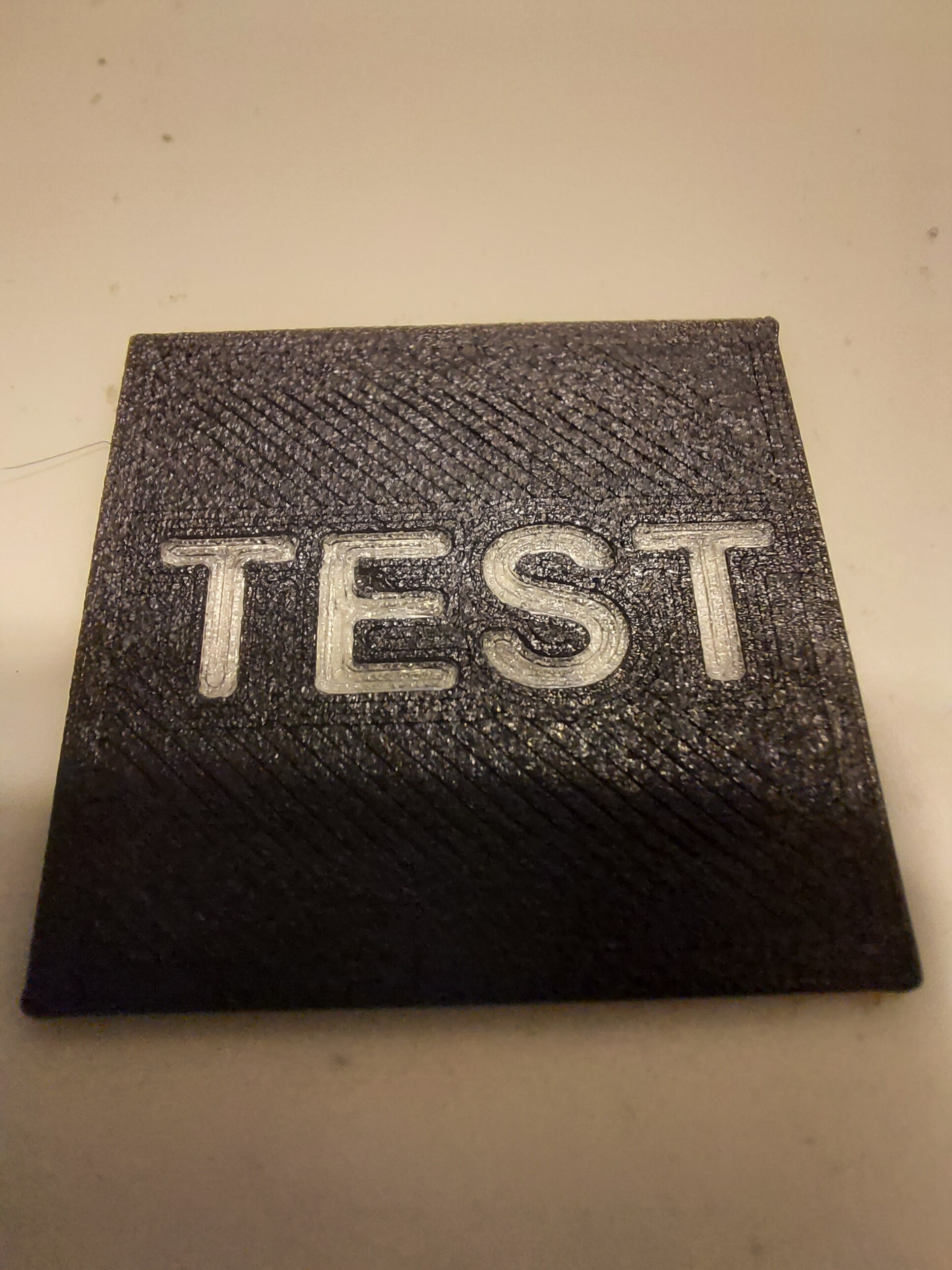
There is a method you could use, but it takes some planning. You basically print a second model without removing the first. It's easier to do face-down as an inlay, and I've done a test piece where text was backlightable by making the text into through holes in the main part. This is the method I used: https://youtu.be/0Sla-vIsvh4

-
Switches don't take up much time, but analogue devices take a while to read and convert the result, so it might help to separate gauge drivers from input devices. It might also help to split the gauges over a few devices, particularly if they're stepper driven. Servo-driven gauges can be run from PWM outputs and/or dedicated drivers that can cut the Arduino processor overhead dramatically compared to stepper driving.
-
I just ran a quick test, and an Uno DOES work as a slave device. I was using it as a radio display (driving an LCD). The output was a bit flaky sometimes, but that's more than likely the VERY rough rats' nest breadboard setup I was using.
-
He wrote "Maybe three Uno boards would be better but I am not sure whether they can be used as slaves." To my mind, that's asking if Unos can be used as slaves. Particularly as the original examples in this thread are Nanos.
-
The Megas are used as masters as they have more than one hardware UART, so the main one is used for the USB interface, and a second one is used for the RS485 network. Unos, Nanos, etc. have only one hardware UART, and can be used as slaves on an RS485 network. Unos and Nanos are electronically very similar, and the only programming differences relate to the different IO pin numbers and types available, so yes, Unos CAN be used as RS 485 slave devices.
-
It might be needing some kind of "thin walls" setting to be turned on.
-
For "self-build" control inputs, have you considered a Leo Bodnar board? They have 12-bit ADCs, so better resolution than the standard Arduino 10-bit. There's no coding to deal with - just plug it in and the computer sees it as a game controller. They can also be configured to operate with rotary encoders. http://www.leobodnar.com/shop/index.php?main_page=index&cPath=94&zenid=266e90cd3c9323cbc52e5bb4a111beb8 Oh, BTW, total-lossing an A-10 while trying not to takes talent!
-
Exporting and driving a caution panel for the huey
No1sonuk replied to Studsmcgee's topic in Home Cockpits
The mating half is possibly 26-20S. 20 indicators puzzles me. Only 4 circuits are shown, and they're all different.