Hajime
-
Posts
44 -
Joined
-
Last visited
Content Type
Profiles
Forums
Events
Everything posted by Hajime
-
I did not tried it but my suggestion: Go to the Mission Planer right before you click "Fly" There you can see the your flight and also can see the Datalink "Numbers" (I don't know what they are called). Write them down. Start up the jet and see if they are correct. If yes. Cycle the GPS time On/Off and then it should work.
-
nullHey, I just started the Gamblers Campaign and unfortunately I don't have DLink GPS Time is on Any suggestions? Hajime

-
I tested the same thing with the BS3-Module. It is the same. Even with Cold start, normal aligmnent and "realistic INS" disabled. QFE ist set. The problem cannot be attributed to INS drift, Aligment errors etc. If you make your prober coldstart, alignment etc. and you just hover directly over your starting position (so that your LAT LONG Position is the same apart from the altitude). Then you lock a target. With your laser ranger you get a offset position (range and bearing) relative to your position. The flight computer is calculating the position of the locked target from your position + the offset (range and bearing). So if you now call up that datalink position a short time after (e.g. 10s). The Shkval has to slew to the same position, regardless of a eventual faulty INS position at the time you reccord that datalink position. There could only be a big error between the stored and called position if there is a position drift in that 10s. That can't make sense from a technical point of view. @BIGNEWY@NineLine
-
Hey I noticed, that the Ka-50 Datalink does not work properly (SP & MP). When I save a target (air start) and want to slew back to the target there is always a big offset to the right. This also happens with shared targets in MP. Edit: As I watched the track. It feels odd, that the Skval is not pointing directly on the vehicles as I locked them. I'm 100% sure i locked the vehicle itself and not the ground next to it. Ka-50-Track.trk
-
reported FARP-Type changing after Saving .miz
Hajime replied to Hajime's topic in Mission Editor Bugs
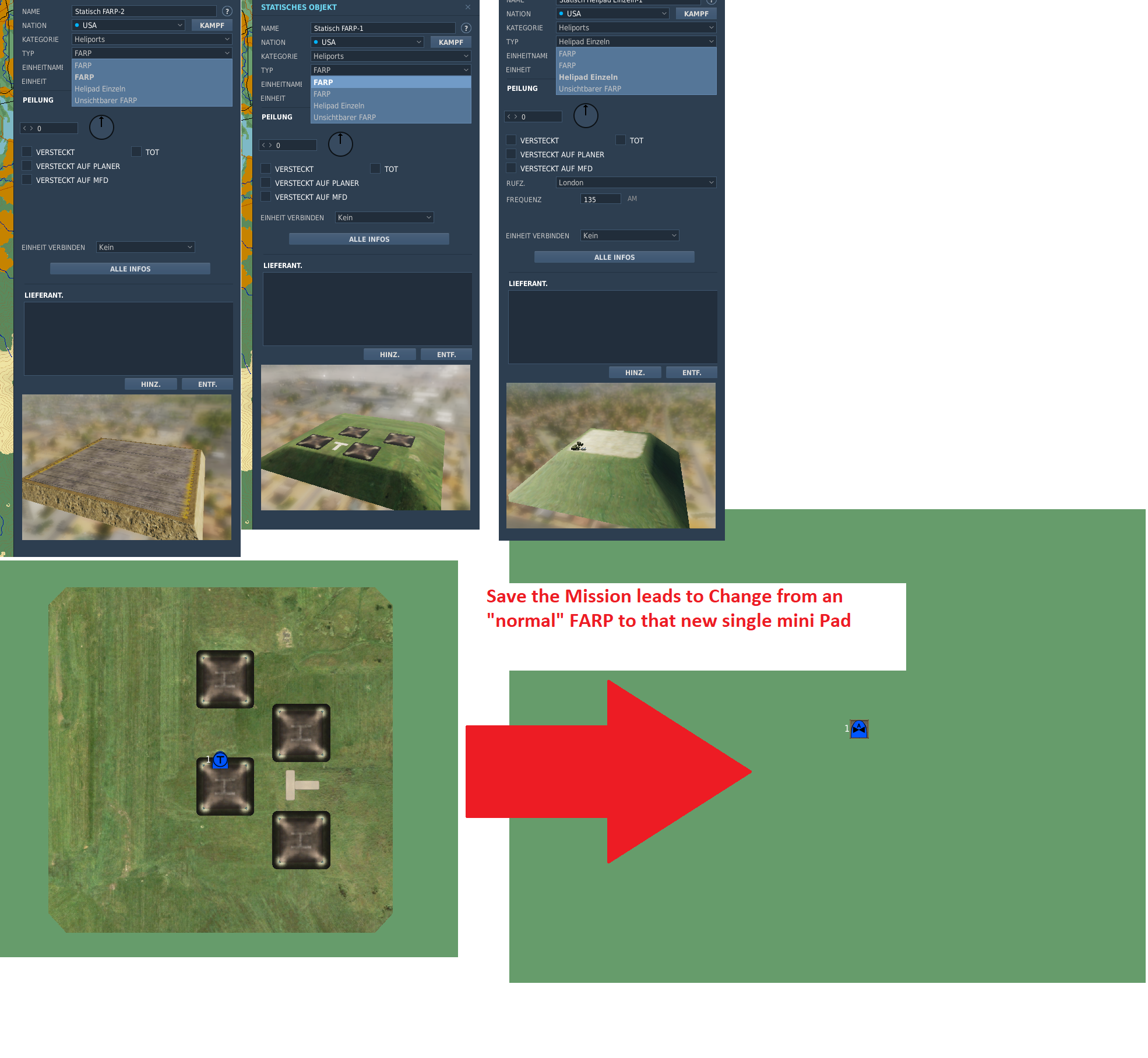
It seems to be a problem with the German translation. When I change to the English version the problem does not occur. The "FARP" and the "PAD Single" are not named the same, as in the German Version. When I change back to German the problem is also back. So there should be the reason. -
reported FARP-Type changing after Saving .miz
Hajime replied to Hajime's topic in Mission Editor Bugs
@Flappie No Problem. Sorry, for answering slowly myself. I have tried it, but the result is the same. -
reported FARP-Type changing after Saving .miz
Hajime replied to Hajime's topic in Mission Editor Bugs
Were you able to take a look into the files? -
reported FARP-Type changing after Saving .miz
Hajime replied to Hajime's topic in Mission Editor Bugs
I added you the .miz and my log Test_Bug.miz dcs.log -
Hey I noticed a strange behaviour. If I place a normal FARP and Save the .miz the FARP changes to the new "mini farp pad". I noticed that the normal FARP and the new Pad are named the same (see picture). I already repaired my DCS to preclude errors in my installation
-
How is the state of the mod? I thought about trying it out, but the last release I found ist from May 2021 is that right?
-
Wer wir sind: Wir sind die GTAG Attack Group. Wir gehören zu der auf Luftkampf ausgerichteten GTAG (siehe oben) und überschneiden uns z.T. auch personell, sind jedoch eine unabhängige Hubschrauberstaffel. Organisatorisches: Wir haben derzeit einen Piloten/CPG-Pool von 10-15 Personen und möchten weiter wachsen um möglichst viele Aspekte der Hubschrauberfliegerei abzudecken. Unser derzeitiger Trainingstermin ist: Haupttraining: Dienstag 20:00 Uhr Eine prinzipielle Anwesenheitspflicht gibt es nicht. Eine Regelmäßige Teilnahme ist natürlich gerne gesehen, aber Reallife geht immer vor! Es ist immer gerne gesehen wenn sich Piloten in die Trainings-/ Eventgestaltung einbringen möchten. Wo stehen wir? Wo wollen wir hin? Unsere Trainings finden jedoch jede Woche Dienstags 20:00 Uhr statt. Der Trainingsschwerpunkt liegt auf Verfahren, Taktiken und das fliegen von Missionen. Unser Anspruch ist es dabei, die Hubschrauber in einem sinnvollen Realismusgrad zu fliegen. Das bedeutet für uns neben den grundlegenden Airport-Verfahren, hauptsächlich das Nutzen von realitätsnaher Hubschraubertaktik und das Zusammenwirken von unterschiedlichen Hubschraubertypen (z.B. Kampf- und Transporthubschrauber). Wir lehnen uns dabei an die deutsche Heeresfliegerei an. Es geht uns also nicht darum, dass jeder Pilot/CPG möglichst viele Abschüsse erzielt, sondern gemeinsam sinnvoll und strukturiert vorzugehen um das Missionsziel zu erreichen. Schießbuden sind bei uns nicht vorgesehen. Unsere derzeitigen Hauptmuster sind der Apache, Mi8 und Ka-50. Andere Hubschrauber, vorallem Transporthubschrauberpiloten, sind explizit willkommen. Wen suchen wir? - Piloten die commited sind, sich mit Hubschraubern ernsthaft auseinander zu setzen (wir sind trotzdem nicht spaßbefreit ) - Grundlegendes beherrschen des Musters - Piloten 18+ mit Discord und SRS Zusammenfassung: WER?: GTAG Attack Group WAS?: Hubschrauberstaffel WANN?: Dienstags 20:00 Uhr MUSTER?: Apache, Ka-50, Mi-8 + alle anderen Helis Wir fliegen die DCS open Beta GTAG Discord: https://discord.gg/Z4xZpDkC Alternativ: [GTAG] Hajime#6634
-
ACES LFE 22-1 (22 Vs 18 PvP Event Powered by Fox3.MS)
Hajime replied to Phoenix Task Force's topic in Tournaments & Events
6x F-16 [SWEEP/ ESCORT] [GTAG] Gozar [GTAG] audax [GTAG] Bishop [GTAG] NightRaid [GTAG] Hajime [GTAG] Hooti -
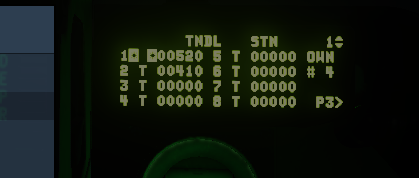
Moin, ich hoffe dieser Thread ist noch nicht tot Ich nutz DCS-BIOS für meine Button Boxes aufgrund der Fähigkeit durch DCS LEDs zu schalten und Encoder einzubinden. Ich habe nun bei meinem Ka-50 Datalink Panel das Phänomen, dass die LEDs z.T. zufällig aufleuchten. Die LED bleiben dann an und flackern nicht. Wenn dies im Ka-50 passiert erlöschen die Lichter wenn ich eine Taste drücke die in DCS mit einem Tastendruck verknüpft ist. Das Aufleuchten ist unabhängig davon, ob ich den Ka-50 fliege oder nicht. z.T. geschieht dies (wiederholbar) beim Vorspulen im Singleplayer. Jedoch auch während der normalen Benutzung im Multiplayer / Singleplayer. Der Code anbei. Ich nutze einen Arduino MEGA. Den Delay im Loop habe ich hinzugefügt, weil ich ohne Mehrfachbetätigungen der Tasten habe. #define DCSBIOS_DEFAULT_SERIAL #include "DcsBios.h" // LED DcsBios::LED dlnkTargetVehicleLed(0x180e, 0x0080, 5); DcsBios::LED dlnkTargetSamLed(0x180e, 0x0200, 3); DcsBios::LED dlnkTargetOtherLed(0x180e, 0x0800, 2); DcsBios::LED dlnkTargetPointLed(0x180e, 0x2000, 4); // Haus bzw. Initialpunkt DcsBios::LED dlnkWingmanAllLed(0x180c, 0x2000, 6); DcsBios::LED dlnkWingman4Led(0x180e, 0x0020, 7); DcsBios::LED dlnkWingman3Led(0x180e, 0x0008, 9); DcsBios::LED dlnkWingman2Led(0x180e, 0x0002, 8); DcsBios::LED dlnkWingman1Led(0x180c, 0x8000, 11); DcsBios::LED dlnkSendLed(0x180c, 0x0020, 10); DcsBios::LED dlnkEscapeLed(0x180c, 0x0080, 12); // DL ingreass DcsBios::LED dlnkEraseLed(0x180c, 0x0200, 14); DcsBios::LED dlnkCleanLed(0x180c, 0x0800, 16); // Buttons DcsBios::Switch2Pos dlnkTargetVehicleBtn("DLNK_TARGET_VEHICLE_BTN", 41); DcsBios::Switch2Pos dlnkTargetSamBtn("DLNK_TARGET_SAM_BTN", 42); DcsBios::Switch2Pos dlnkTargetOtherBtn("DLNK_TARGET_OTHER_BTN", 40); DcsBios::Switch2Pos dlnkTargetPointBtn("DLNK_TARGET_POINT_BTN", 39); // Haus bzw. Initialpunkt DcsBios::Switch2Pos dlnkWingman1Btn("DLNK_WINGMAN_1_BTN", A14); // DcsBios::Switch2Pos dlnkWingman2Btn("DLNK_WINGMAN_2_BTN", 32); // DcsBios::Switch2Pos dlnkWingman3Btn("DLNK_WINGMAN_3_BTN", 34); // DcsBios::Switch2Pos dlnkWingman4Btn("DLNK_WINGMAN_4_BTN", 36); // DcsBios::Switch2Pos dlnkWingmanAllBtn("DLNK_WINGMAN_ALL_BTN", 38); // DcsBios::Switch2Pos dlnkCleanBtn("DLNK_CLEAN_BTN", 46); DcsBios::Switch2Pos dlnkEraseBtn("DLNK_ERASE_BTN", 44); // Clear DcsBios::Switch2Pos dlnkEscapeBtn("DLNK_ESCAPE_BTN", 47); // DL ingress DcsBios::Switch2Pos dlnkSendBtn("DLNK_SEND_BTN", 45); void setup() { DcsBios::setup(); } void loop() { DcsBios::loop(); delay(50); }
-
Thank you for your answer. Honestly Iam more interested to learn the size and position of the buttons relative to each other and to the screen. I tried to measure it from the drawing you linked, but it is quite inaccurate. But I give it a try. I want to avoid to build a MFD with PCB etc. and then realize that the button position does not match to the screen (and I do not want to wait until the Apache is released) So I would love to have a detailed .dxf or a drawing. I can post my measurements when I finished it. P.S. Converting inch to mm and back all the time hurts my brain and setting my CAD-system to inch feels like my skin is burning No offense Thanks.
-
DCS INTERCOMMUNITY EVENT: Real War 3.0 - Operation White Blade
Hajime replied to Satarosa's topic in Community News
Hi, is there a reason why we start that far away? -
DCS INTERCOMMUNITY EVENT: Real War 3.0 - Operation White Blade
Hajime replied to Satarosa's topic in Community News
[GTAG] Papa Saubär [GTAG] Bishop_DE [GTAG] Ari [GTAG] Hajime + possible Gunners (not confirmed) Can you place them all at the same location? Standard Georgian Skin is ok. -
Do you have a link? They look as they fit to be painted an engraved. Your MFDs designs look very great. You said you consider to share your design files. Hence I don't want to push you, would you be so nice to share at least the outline dimensions? I want to start building my own MFDs, but I did not find any dimensions for them yet. Thanks in advance! Hajime
-
DCS INTERCOMMUNITY EVENT: Real War 3.0 - Operation White Blade
Hajime replied to Satarosa's topic in Community News
Request 4x Mi24P Groundattack II -
It looks really nice. Which Buttons do you use for the "emergency panel"?
-
Hello, I am searching for the Dimensions of the Datalink-Panel of the Ka-50. There are some old threads which adress that topic but their links are not working anymore. Of course I am also interesseted in other drawings / dimensions of the Ka-50 cockpit . Can anyone help? Greetings Hajime
-
I was on vacation so I was not able to answer. Sorry for that. Thank you for your ideas, if I have something to show, i will post it
-
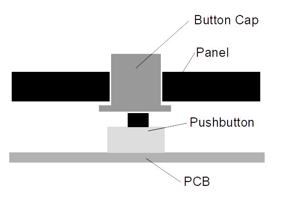
Hello, I'm planning to build a Viper-like ICP / UFC panel, but I already see 2 issues. Over and over again I browse the Internet to find out, how to make buttoncaps with labelling which are transperent to led light. How do you make them? Do you print the shape of the button cap in a transparent material in a resin-printer, paint it and engrave the label with a laser? I noticed that often the button caps are sitting lose on top of the pushbuttons and are only kept in place by the springforce of the button and the guide of the panel? Is that a satisfactory method? I am an absolute beginner to the "mechanical" side of panel building, so I appreciate your help. Greetings Hajime
-
Thank you!
-
Hey, I just bought a VKB MCG Stick with the Gunfighter III Base and I want to adapt my current stick holding plate to the new dimensions, before the stick arrives here. (I didn't find a manual for the Stick / Base). The image below is from another ED-Forum thread, is the hole pattern for the Gunfighter MK2 the same as for the MK 3? I asume that the 5 mm holes are used to mount the plate to the base? Thanks.
-
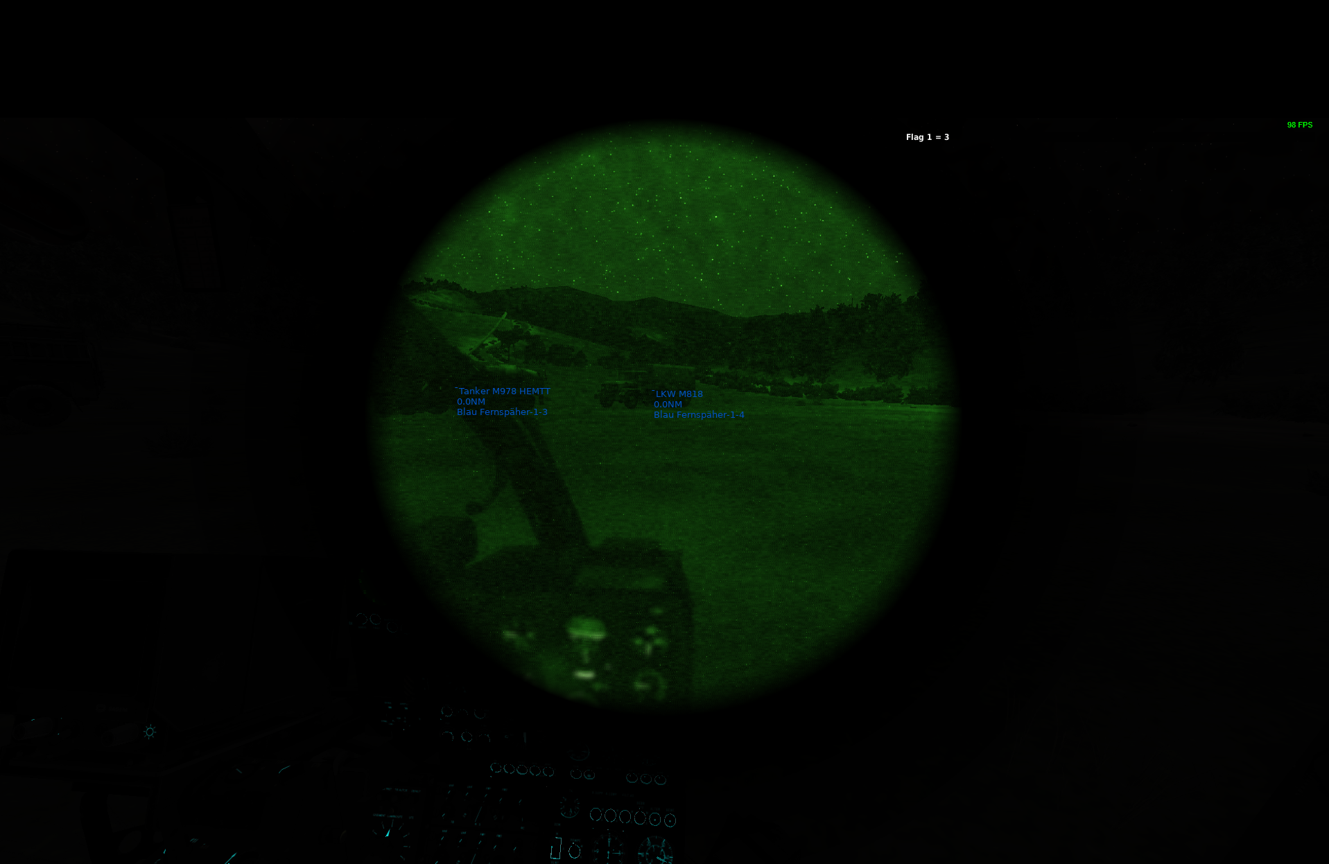
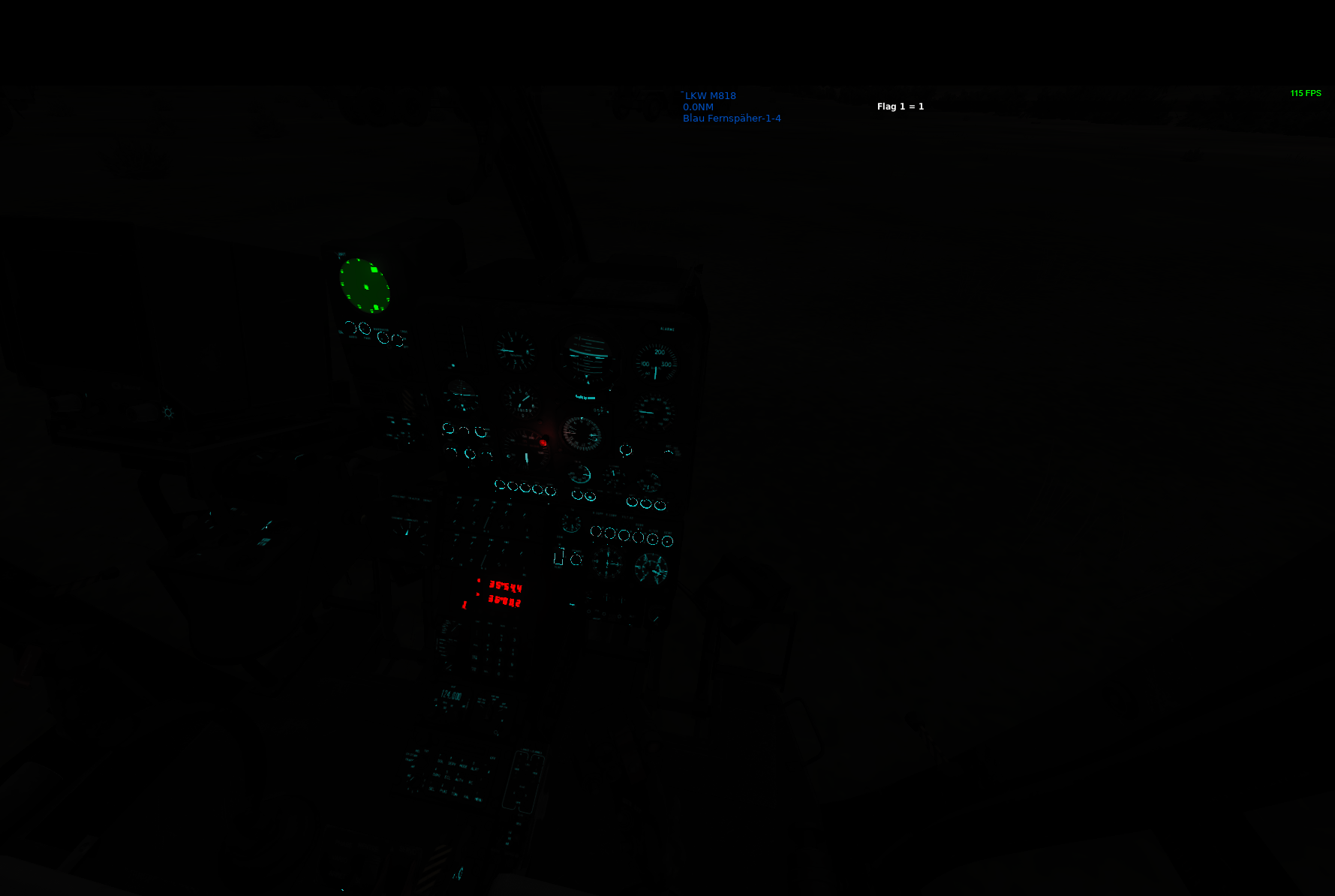
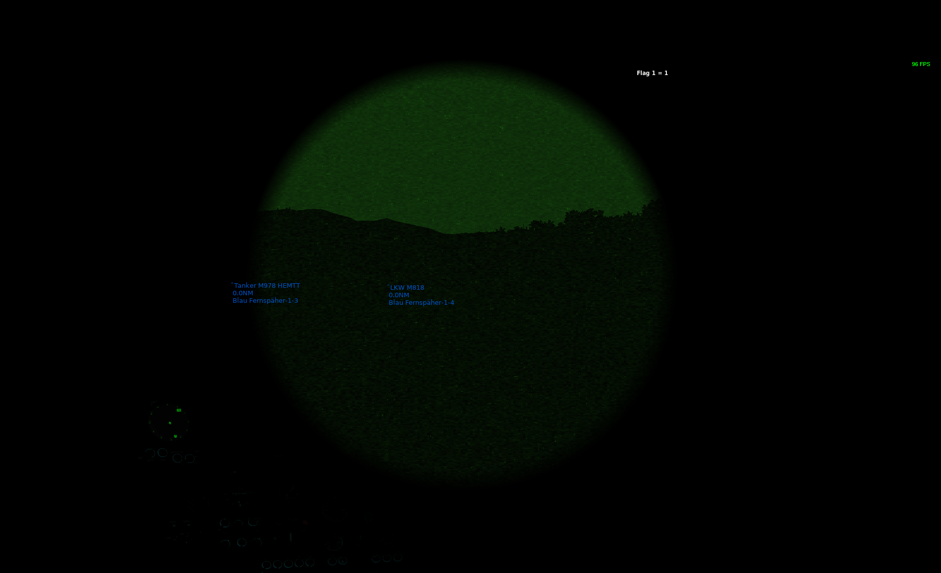
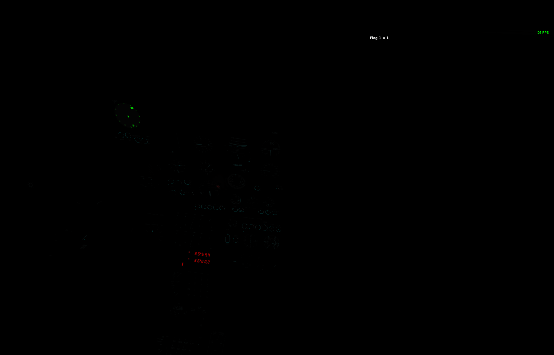
Hey, I tried out the NVG on the Gazelle and there is a strange behaviour. Sometimes the NVG Vision is really bad. I start the mission, jump in the Heli (HOT) and toggle the NVG. I noticed that the cockpit lights differs too in that two cases. I don't tuch anything after starting the mission. 1. Picture: NVG working 2. Picture: Cockpit Lights 3. Picture: NVG not working 4. Picture: Cockpit Lights dim Any suggestions? NVG Working Cockpit lights NVG not working Cockpit lights dim