
Hempstead
-
Posts
472 -
Joined
-
Last visited
Content Type
Profiles
Forums
Events
Everything posted by Hempstead
-

What's up with the price of button boxes?
Hempstead replied to Nightdare's topic in PC Hardware and Related Software
DCS seems to have the same problem. If a controller is not listed in the preferred game controllers when you open the Devices & Printers, select any gaming controller, r-click and select "Game Controller Properties". If your controller is not listed in the little un-resizeable little popup box, then, DCS doesn't seem to be able to access it. I have 2 Razer optical keyboards, a Razer Tartarus game pad... each has analog optical keys... and they all wanted to emulate XBox 360 game pads... thus showing up with 3 additional XBox 306 gaming pads... and it seems M$ prefers to list XBox 360 pads instead of "others'." Meaning, when I plugged in TM TCA yoke/box, TM Warthog stick/throttle, TM Pendulum Rudder, and then TM Viper TQS... or even a Hempstick,... some of them won't show up on that list... and guess which ones don't get "preferred?" What I see is that any controller doesn't show up on this list will not show up on the Control config screen of DCS, and the input of such controller will not be read by DCS. My guess is that DCS is still using DirectInput, limited to 8 controllers (not a bad thing, b/c the newer console-centric XInput will only allow 4 controllers; 8 is still better than 4 from our PoV). Anyway.... if you want more than 8, you'd have to combine a bunch of them using either vJoy or TARGET. -
Ultraleap.... have to reinstall DCS!
Hempstead replied to Hempstead's topic in PC Hardware and Related Software
Reinstall DCS worked. That means, Ultraleap modified my DCS settings and/or installation without notifying me, nor my permission, not in the OS, nor OpenXR layer. Originally, I had DCS release installation, i.e. DCS World, then converted to OpenBeta, so my directories had the names "DCS World" instead of "DCS World Openbeta." Now, I directly downloaded and installed OpenBeta. And I also renamed the old DCS World installation directory to "DCS World.old" so it doesn't get overwritten, and got some Ultraleap modified leftover stuff. This way, I can be sure both the installation and Saved Game Data are new without any leftover. Also the old files in the Save Game Data are preserved (so I can copy my input configurations back; my git repo for this dir was a bit old as I am still testing 2.9 settings and the new TM Viper TQS + Warthog throttle combo). But this also means that Ultraleap's uninstaller did not cleanup after itself regarding its "unauthorized" modification of DCS. There is one other possibility... DCS detected Ultraleap and modified itself or my settings to get that... and when Ultraleap was uninstalled... it breaks. I don't know which. I am sure there is an easier way than to uninstall and reinstall/download the 400+GB of modules... but I can't find it with google. What else did Ultraleap break? MSFS 2020? I don't know. -
Urgh... I bought an Ultraleap 2 for an experiment for an idea.... installed the tracking software... ran it... it seems to track my finger tips quite accurately (that's what I need, because Oculus Quest Pro's hand tracking is very inaccurate in the Z direction; try hold out both of your arms flat out, and try to touch your two index fingers together in VR, not passthrough, it's about 2 cm off in the Z direction). BUT... going into ED now gets me no Oculus controllers! In the [Settings] --> [VR] tab, it showed a blank page, and took forever to finally filled it up with options... and to my surprise... VR controller is disabled, and the only other option is Ultraleap! Going to the [Special] --> [UltraLeap] options, and it tells me to "Disable the VR controller in the VR tab...." I didn't want Ultraleap... I just wanted to test it... not getting hijacked by Ultraleap! My quest controller works great for now.... Found no way to disable it... after an hour of googling... so I uninstalled Ultraleap software... and now DCS crashes. Now I am uninstalling/installing DCS...
-
Sorry about that, I copied URL of the "Preview" link as the blog author... instead of what the public would need. Here's the URL for the public. https://blog.hempstick.org/2023/09/a-pit-finally.html Ok... I do have a lot of tools... including several CNC mills/routers, and a lot more tools that go with them... but, this one is an easy build. Except cutting the aluminum extrusion, cutting the L-brackets, and drilling the L-brackets.... this thing is pretty much build in place, right in my home office, which is combined with my gaming space. I just pushed my office chair away. Cutting the extrusions and the L-brackets... a hack saw will do just fine.... it's just that a USD$99 band saw will make your life a lot easier with less swearing, same goes to cutting the L-brackets. Oh, well, same goes to the $99 drill press. I did use my CNC mill as a drill press, and my hydraulically controlled metal cutting bandsaw to cut the aluminum, but I didn't use any other tools in the garage other than deburrer and such simple hand tools. The $99 bandsaw and $99 drill press are usually designed for wood... so they are way too fast for doing metal works... but for the small amount you need to do... they will do ok. Just don't push too hard and let the tools do the work instead of forcing them. Except cutting/drilling the extrusion and L-brackets, the only space I used was the space the "pit" eventually occupied and the space my office chair occupied, plus a strip of 1'x6' space next to the pit (you know, laying out the tools and screws for easy access.) It's a 56" x 78" space. Once you cut/drill the stuff you need, it's very IKEA, except there is no instruction booklet. Oh... if the NLR Boeing ed. is > USD $1,000, then, this solution not only is hell more flexible, it's quite a bit cheaper, particularly if you go for the cloner extrusions.
-
https://www.blogger.com/blog/post/edit/1634444484406261711/5159989745868759669 Build in a weekend (in the first post, linked above). I use the original 80/20 extrusion.... they are much more expensive than the cloner stuff. But note that for this stuff, the connectors are the expensive stuff. However, I figured out to use just L-shaped aluminum bars cut into L brackets with two holes drilled into each. That saves a lot of money... and most importantly the damn-it-I-need-more-of-this-bracket-order-wait-for-shipment problem. All you need for tools are a bandsaw, a drill press, and some hand tools. This one you see in the blog was made with 2020 (2"x2") and 1010null (1"x1"). 2020 members are used for main structure, and 1010 members are used for just mounting the "instruments and controllers." Total cost is not much cheaper than Next Level Racing... (just the IKON racing chair is about $250).... but it's immensely more flexible (I have already reconfigured it 3 times).
-
Is there any immersive way to interact with the cockpit?
Hempstead replied to dlder's topic in Virtual Reality
Well, it does have a pointer, and used to have a laser beam too but the MT release broke the laser beam... and I mean using the trigger, buttons, and thumbstick to manipulate the buttons, toggles, and dials. Directly using the virtual fingers to press/flip/rotate is just difficult. For instance, with the F-16 HSI HDG dial trying to set your heading... I use the thumb stick to do that. It's difficult to get within a degree precisely, but I can easily do two degree resolution. -
Added more stuff to the "pit." Mind you, I ain't building a 1:1 pit. I am building a pit for functionalities and flexibility. https://blog.hempstick.org/2023/09/to-pit-to-pit-add-more-stuff-to-pit.html
-
Is there any immersive way to interact with the cockpit?
Hempstead replied to dlder's topic in Virtual Reality
Sure... send me an offer. I reserve the right to cancel the deal and refund if the shipping cost is too crazy. I mean, if the shipping cost is like USD $100, then I might as well just keep it. -
Is there any immersive way to interact with the cockpit?
Hempstead replied to dlder's topic in Virtual Reality
I don't have Crystal, but my Quest 2, and now Quest Pro controllers are just as precise as a mouse, if not more so. Works great! So great that I never opened my PointCtl. I will sell you my unopened PointCtrl if you want (if I can find where I put it. ;-). A simple strap work solves the problem, although I have to admit, the right stick hand with a monkey on the back is very annoying particularly in a dog fight. I don't hang the right hand controller though. I only use the right hand controller when I am on the ground doing cold start anyway. -
Haven't posted for awhile. Due to family issues and a bit of health issue. Anyway, I finally decided to build a kinda pit... to get around my health issue. https://blog.hempstick.org/2023/09/a-pit-finally.html
-
Eye tracking control of in cockpit switches
Hempstead replied to Mr_sukebe's topic in Virtual Reality
Works just fine... -
https://blog.hempstick.org/2023/07/price-comparison-between-shapeways-and.html I don't know about you... the price differences between DIY and Shapeways are just too big... PA12 on Shapeways costs > $100 than printing it yourself with PA12 + CF. But, it's an option for those DIY challenged... on the other hand, if you are DIY challenged, you should not be reading this thread to begin with. Unfortunately, PA12 burned fume is toxic. So, it will be difficult to get this mil-spec. approved.
-
https://blog.hempstick.org/2023/07/design-one-thing-test-many-times.html Don't you ever say I never test my designs!
-
https://blog.hempstick.org/2023/07/kids-dont-do-ldpe.html LDPE slumps too much... no good as a bag. But the useless good news is that it does not bond to Nylon.
-
https://blog.hempstick.org/2023/07/sous-vide-test-on-nylon12cf-controller.html Sous Vide Annealing Test is a success! Note that it's going to be difficult to do this with a Sous Vide stick in immersion mode, because it's difficult for them to reach 90˚C or even 100˚C Nylon12 needed. But for other plastics with lower glass transition temperatures, it might be viable. However, I am thinking, if it's exactly 100˚C that you need to hold.... you could basically red neck it by steaming it for 12 hrs... I mean buy a cheap aluminum steaming basket, a big pot... and steam it on your stove top for 12 hrs... it's just that you might have to top off the water several times.... maintaining 12 hrs steam is a chore all by itself.
-
https://blog.hempstick.org/2023/07/sous-vide-f16-like-control-stick.html Sous Vide my Nylon12 Carbon Fiber F16-like Control Stick 3D print!!! I mean, Annealing! I was shopping for an oven suitable for annealing 3D prints at the right temperature.... although in the back of my mind, I have wanted to do it in one of my ovens... or the jerky oven I have ordered. There are a couple of problems. 1. Although Nylon and Carbon Fiber are both non-toxic, that's not the same as food-safe, or food-grade. Particularly, this filament is made in china -- the land of gutter oil. Whether it's made in china or not is immaterial, the fact that it's not marked as food-grade or food-safe, it's a no go into my regular ovens for cooking food! 2. Regular ovens are not instruments... precision is kind of a concept that does not get talked about in culinary "arts." And my old built-in large oven is from the 1980s... analog control mechanical alarm/timer, and all that. My better oven... the Anova Precision Oven... all modern and all that and there is even an app for it to program and control through WiFi. But.... again, it's for food! 3. The new Jerky Dryer I ordered (still to be delivered) is meant for drying filaments, not for food. And it could only do about 80˚C, just shy of the minimal 90˚C required for Nylon. It can be used to anneal PLA and others but not for Nylon. So, it hit me.... when I narrowed down the model of oven to buy.... Why don't I just vacuum bag that thing in a food safe plastic bag and throw it in my Anova Precision Oven and do that bagless Sous Vide thing? Your regular Sous Vide stick in water immersion operation cannot do more than 100˚C, but this Anova Precision Oven can do higher than 100˚C bagless, non-immersion, Sous Vide! In it goes... We will find out if I ruined a perfectly good print tomorrow!
-
https://blog.hempstick.org/2023/07/carbon-goodness-or-bronze-goodness.html Carbon or Bronze?
-
https://blog.hempstick.org/2023/07/f16-like-controller-trigger-assembly.html Fit test for the trigger assembly groove.
-
https://blog.hempstick.org/2023/07/f16-like-stick-body-pla-matte-printing.html I can tell you that I am definitely going for the Nylon12 Carbon Fiber. It's very strong. Too bad that Nylon12 generates toxic smoke when burned. So, most likely it won't qualify for mil-spec in the cockpit. But PETG might pass... I have two spool of PETG Carbon Fiber, I should print one of those for study. Anyway... qualifying for mil-spec is not one of my goal. But it might be good for a simulator. Supposedly, Nylon 12 is not that much stronger than PETG... and it's less hygroscopic than Nylon. Printing Nylon is an annoying business... you have to dry the filament (oven for 12 hrs), and/or have to have a filament enclosure, or else. And it's picky on print plate material and glue stick you use... PETG is not that picky. 12 hrs printing... minimal post processing, on a USD $1,500 printer (raw material is about $25)... that makes it commercially viable if you are willing to setup a print farm. But... this is designed for home made, with just a printer and some simple home tools (well... plus some specialized tools and parts you still have to buy). But if you can afford a USD $1,500 printer. You can afford to make it. I will let others have it for free... if only I can figure out a way to share without getting my IP stolen and then be accused of stealing from LMCO, again.
-
https://blog.hempstick.org/2023/07/f16-like-control-stick-assembly-grooves.html
-
That's it... New stuff will be posted here, https://blog.hempstick.org/ The stuff is really hosted by blogger.com, by Google, not on my servers at home. I just set it up to use my own domain DNS entry for the redirect. So, even if I got hit by a bus tomorrow, the stuff will stay online...
-
WTH? Now that I figured out a way to generate higher resolution but smaller file size to fit the 500kB limit. Looks like there is a total upload limit.... 200MB. Should I got and delete all my past posts? Create another account, or just leave?

-
Looks like I am going to have to reconsider the plan on hosting my own blog on my own hardware/website for this stuff. That is... abandon this thread altogether. I can host the not-so-large pictures on my own servers/staticIP/DNS etc., and refer to them from here... but I hate that idea... as you well all know forums are filled with broken links pointing to pictures hosted on some previously-popular-pictures-hosting-sites-now-defunkt.
-
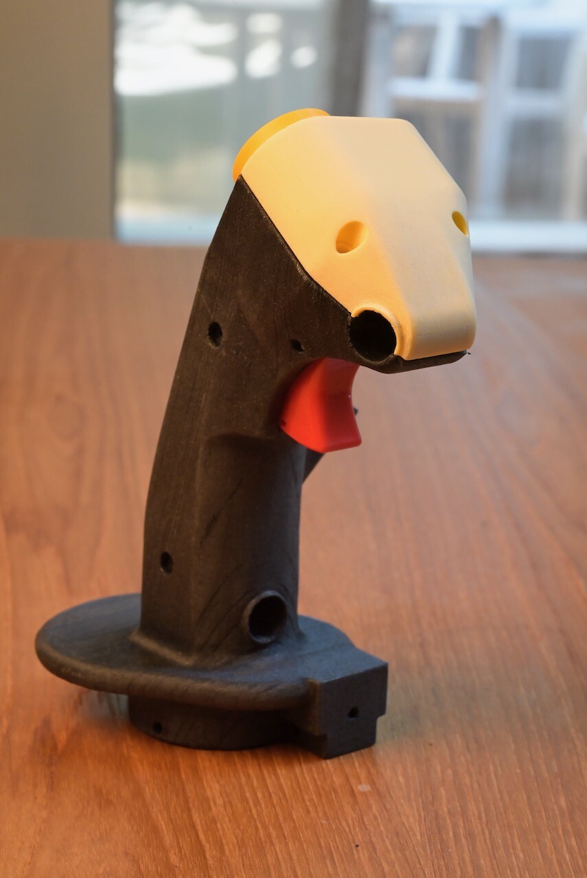
ED forum is now enforcing 500KB per file upload limit... So, you are now treated with the lowest quality pictures I can produce to fit that limit. For crying out loud... disk space is dirt cheap! Anyway... a fit test with previously printed PLA parts... fits just fine... well, mostly... It's a bit tight, and I would have to force it a bit.... and the top cover does not sit 100% flat (needs a bit sanding... I am guessing it's shrinking/warping that is expected of 3D printed parts.. particularly between two different materials). Also found another problem.... See the 3 rivets on the genuine OTTO trigger? Well... I didn't model the extrusion. And the stick was originally designed to be split into two halves... I did encounter a bit of a problem when doing the test fit for the split two halves. So, I designed in a recess for the top pivot rivet. And the two lower ones? Don't care... screw down and the plastic will yield... even better. But that is a problem with the one-piece print.... My tolerance was designed just right... I modeled the NozzleDiameter in it. So, for some critical dimensions, I did reference that NozzleDiameter variable, set to 0.4mm. This way, the trigger will sit in just snug... well.. now I have to design in the "assembly recesses/tracks" for the rivets. Or.... I can use a hammer.
-


.png.be0cfce1dc872f9934b476c4f607021b.png)
.png.3b1914ce04ad5796275c72931b3e4710.png)