Hempstead
-
Posts
472 -
Joined
-
Last visited
Content Type
Profiles
Forums
Events
Everything posted by Hempstead
-
I have always set the device resolutions on Quest 2/pro to max. Then, in DCS I set the PD to 1.0. This way, I can clearly read the Course number on the upper right corner of HSI in F16, without leaning forward, essential in flying a DME arc. The other way of doing it is to set the PD in DCS high, say 1.3, then set Quest Pro’s device resolutions to 1.0x. Try both and see which one you like better. I like setting Quest’s resolution to max better. However, you have to remember to dial this Quest device resolution down before you play MSFS 2020, otherwise you get a slide show, 5fps.
-

Universal military aircraft homecockpit project
Hempstead replied to Viper1970's topic in Home Cockpits
Congrats! -
Thrustmast Warthog Throttle Coolie switch up stopped working
Hempstead replied to Hoggorm's topic in Thrustmaster
Instructions? No. But try this thread, There Sokol provided the replacement part # for the mini push button inside. They are quite cheap. So likely you will have to buy a bunch to justify the s/h charges. These will require some slight modifications, snipping of the leads, to fit. Opening up the throttle us easy. It’s opening up the HAT switch assembly without breaking the soldered wires that’s a bit tricky. To open the throttle, just split the two throttles. In between, on the right throttle, there are 3 screws to unscrew. Then on the right hand side of the right throttle, there is one more screw. Unscrew all 4 and you have it. The main wires going from the throttle base to the right throttle us a bit just short so, it easily come off during disassembly, and us tricky to get plugged back in during reassembly… so, watch out. Those soldering of wires to the HAT switches are very fragile, easily broken during disassembly. Quite a lot if the wires rely on hot glue for structure integrity. Breaking the hot glue blobs for disassembly often inadvertently break the solder joints. So, I would advise marking them with tapes so you can solder them back to the right points in case you break the soldering. So, make sure you have temperature controlled soldering iron and soldering skill, and a pair of tweezers before you open it up. -
Thrustmast Warthog Throttle Coolie switch up stopped working
Hempstead replied to Hoggorm's topic in Thrustmaster
Yes... You are lucky that the Coolie switch is a standalone part that you can buy from TM, unlike the MIC/SpdBrake/Boat/China switches which form a 4-in-one PCB so you must buy the whole thing. Now, since your symptom said the whole Coolie switch stopped functioning... but not other switches, then most likely cause is either the Coolie switch plug got loosen or the power or ground wire is cut (say solder joint broke). See, the Coolie switch is simply constructed out of 4x mini-buttons in one housing. To the MCU they are 4x independent leads. The chance all 4x independent input broke simultaneous is very low. So, likely something common to the 4x inputs broke... hence my guess of either the plug is loose or pwr/gnd wire to the Coolie broke. I'd suggest that you open it up and take a look. -
nullBeen experimenting with Carbon Fiber Composites.... Failed miserably several times in making the bend tube... but I am getting there... still a tiny amount of wrinkle. The next picture is... a mold for forged Carbon Fiber construction. WIP... still need to make the "compression" portion and hardware, like screws or clamps) to press down (the forged part of the method). Note the top and bottom "extra plates" are simply there to fix the location of the core, which a common forged carbon fiber part does not have. The idea is to print the core out of Ultimaker Breakaway... then once the part is de-molded, just dig out the core. At this stage, I can easily construct two separate forged halves. Then epoxy or screw them together. However, I prefer to experiment and see if I can make one complete part at once using this construction method.

-
I stick with Ultimaker filaments, because: 1. I have an Ultimaker 3 printer. All the settings, profiles are fine tuned/verified by Ultimaker on each new version of Cura. Not much tweaking is needed from me. So, I can upgrade to new version of Cura and be relatively sure that my setup is still good without have to tweak it again, and again, and again. My purpose is not playing with 3D printing. It’s a tool for me. I am trying not to fall into that old tinkerers’ trap — working on improving your tools more than you work on what you bought the tools for to begin with. 2. Buying other filaments, I do have a few, is a chore, and a time sink. You often have to experiment quite a bit to get it right for your setup. 3. Yes, Ultimaker filaments are more expensive than others’, but I get consistent quality I can rely on. Peace of mind, you know. I always have a spool of PLA and Breakaway loaded. I can just fire off a print job remotely any time I want from my desktop, and collect the print a few hours later upstairs. I am not recommending Ultimaker filaments. What I am recommending is avoiding the Tinkerers’ Tool Improvement Trap, which I am guilty of in many occasions. Set up one configuration that works for your printer (requires a lot of tweaking) and stick to it. And, if there is one kind of filaments I recommend against, it’s the no name cheap filaments on Amazon. Consistent quality is not a thing for those. Even if you get one filament from some XiLeader working for you, what about the next batch…? The seller might not even exist anymore, let alone consistent quality! Back to tweaking again? Ultimaker has been there as my supplier for filaments for the last 7 years. Will yours be there for you in the next 7? The more time you spend on tweaking your setup to reach a stable configuration you can rely on, the more important this question is to you regarding your selection of filaments. Whatever brand of filament you choose, make sure it’s one that you can rely on for years to come. How many years? Up to you. And I am praying the “merger” of MakerBot and Ultimaker won’t mess up my next 7!
-
First, make sure no controller other than the twist axis of TM160000 is the only one assigned to the rudder function. I do mean all controllers, including your mouse. DCS has a old “legacy” function of assigning any controller you plug in that has x, y, or z axes to raw, pitch, and yaw automatically “for you.” You plug in a new controller, it will automatically assign it for you again on all your profiles for all planes! These unwanted extra bindings could “show” up at weird time, with “undefined” behaviors.
-
I would also highly recommend PETG and PLA. PLA is my go to filament, all around for pretty much everything. Super easy to print. Very easy to sand and smooth out. For instance, for my bronze castings, I print the plug with PLA, then brush with X3D resin to smooth out, then sand to really very smooth, beautiful surface before casting in RTV mold for casting wax patterns. Tough PLA from Ultimaker is also as easy to print as PLA, but it’s a bit more flexible so not as easy to sand and file as PLA, but manageable. PETG is slightly more expensive, but if you want to print mold or patterns for carbon/glass fiber mold/plug, it’s the go to filament. I never have any stringing problem with it with my Ultimaker 3 printer’s default settings though. These days, I rarely print with ABS because it’s difficult to print. It shrinks and distort quite a bit. Even if I could get it to print larger prints, they often have too much internal stress and would crack after air cooling. For instance, I printed my mod of the F16 control stick base with ABS. But it cracked, on 3 different prints. Although those cracks eventually inspired me to split it into 3 pieces and then bolt them together to make it easier for assembly, reinforced with SS bolts, and easier to print, it tells me that ABS is the wrong filament to use for this situation. I do have a pair of F16 pedals a friend printed for me. I have no idea how he did such large prints without cracking, but if I had God’s eyes, I should be able to see quite a lot of internal stress, probably not a good functional part to begin with, which goes against the whole point of ABS being stronger than PLA. In other words, if you are thinking of printing large parts in ABS, you might want to consider other methods, like changing your design (e.x. 3 pieces bolted together), or say PLA wrapped in Carbon Fiber, or forged Carbon Fiber construction.
-
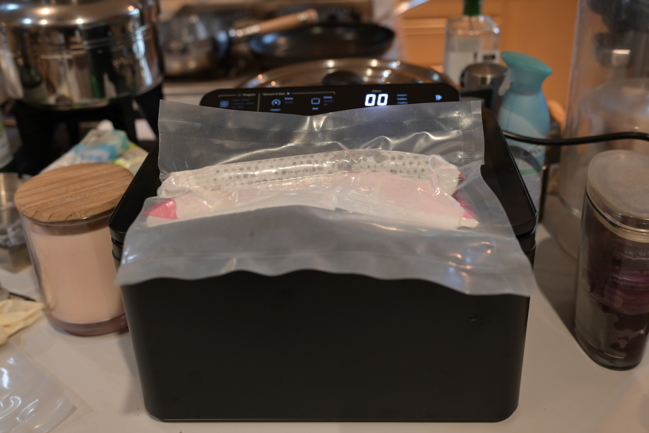
Using the Anova food vacuum... kind of works but not really. Two potential problems. 1. Outgassing... For food preservation, a little outgassing is not a problem. So they don't pump very long, something like 20 seconds, then they heat seal the bag. For composite works though... the outgassing is enough to relieve the pressure vacuum bagging is supposed to do... Outgassing after the heat sealing cannot be removed without an additional valve and pump (or a vacuum pot) connected to it. If I am going to add a valve and a pump... might as well ditch the Anova vacuum. 2. Not hard enough vacuum. Again, for food preservation, you don't really need very high vacuum... all you need is to remove enough oxygen to delay the food decay... and most of the food don't appreciate hard vacuum anyway. So, lessons learned.... I am going to add the vacuum valve back, and then keep the heat seal instead of using the annoying traditional sticky glue sealing tape.... I might try heat shrink tubes as well... Then, use a real vacuum pump (Harbor Freight's el'cheap will do just fine for this small a volume), and a vacuum pot for overflow. I do have a continuous heat sealing machine to create unlimited length plastic bag.
-
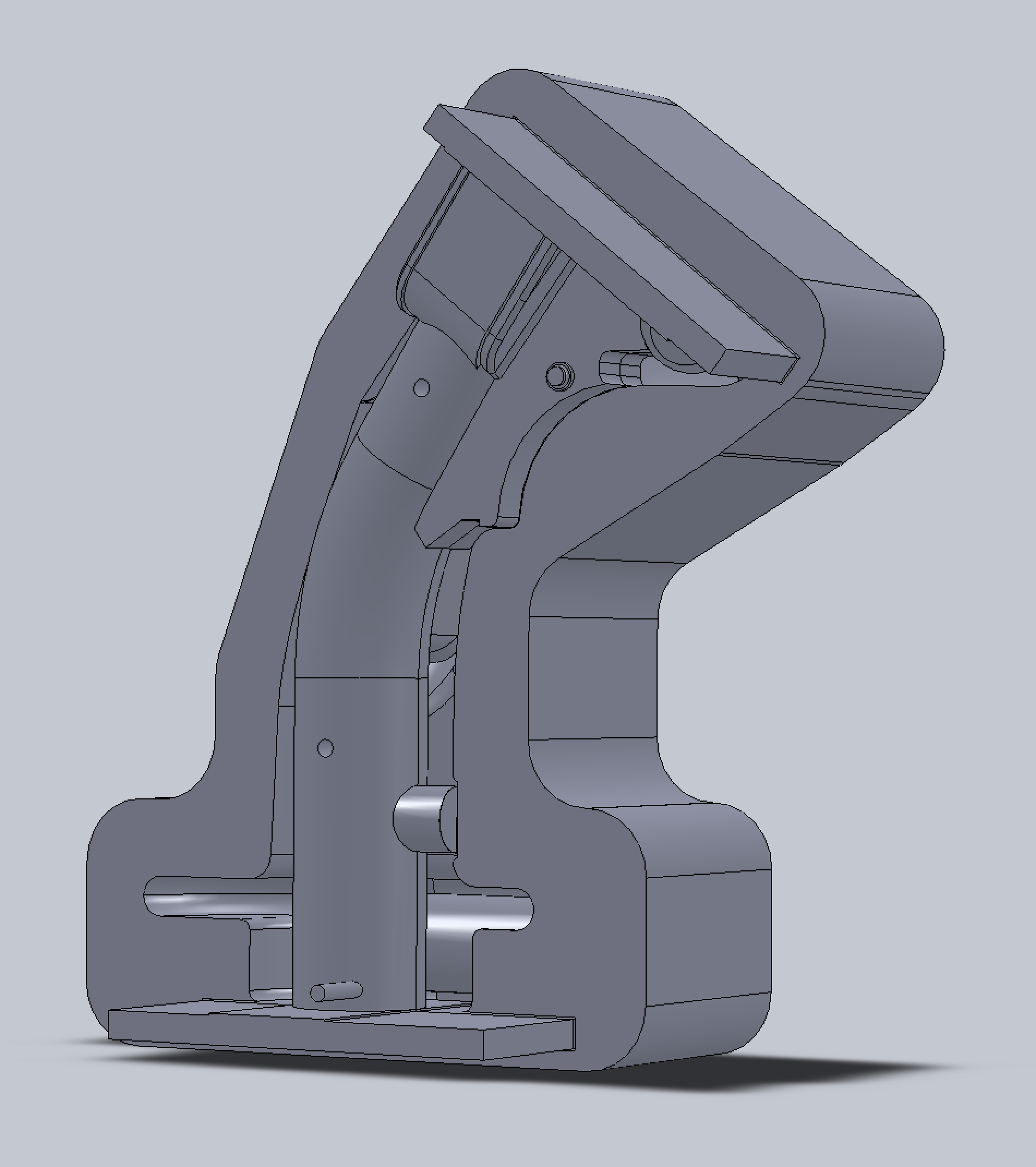
Using my Anova Precision Chamber Vacuum Sealer machine to "cook" the carbon fiber shaft of the F16-like control stick. This is basically the vacuum bagging method, except... instead of the vacuum bag with putty like sealer tape, and a vacuum valve, I used a regular food grade bag (the thickest I can find), and then used the Anova to seal 3 sides to make a pouch, then, treat it like a piece of steak. The great thing about this "mod" is that as long as the part fits... I don't have to fiddle with the annoying sealer tape or valve. Just place the pouch in the machine, setup the machine, press the button. It sucks most of the air out of the chamber, including the air inside the bag, and then, seals the last open edge, and let the air in. The air going in will compress the resin and stuff... then I can just massage the resin and part from outside (not much to do really). It's totally sealed. No fuzz, no trouble... null
-
Update: MT version (OpenXR): Finger Interaction only when Hand Grip is obtained does nothing. It will always interact whether that check box is checked or not. Laser drop box has no effect. Non-MT version (OpenXR): Finger tips will not interact whether that check box is checked or not. Laser drop box works.
-
Outside a mission (in the menu/settings pages), the laser pointer showed up. But inside a mission, the laser pointer disappear, leave a tiny blue cross showing where the VR controller is pointed at. This makes using hand controller much more difficult.
-
There are 3 pins and 5 pins connectors. They are JST EHR-3 or EHR-5. You can go to www.digikey.com and search for EHR-3 or EHR-5 for them. Now. please note that these are just connectors... you also need to buy the pins, SEH-001T-P0.6.
-
Dang... the D=1.5" woven carbon fiber sleeve is just a hair too big for the mold for making the shaft of the control stick. Oh, well... ordered some D=1.0" and wait some more .... This is where having more than one Ph.D.s (Projects Half Dones) is a good thing.
-
null
-
Fitted with 3x planes in Blender! nullThanks to Michael Landers for the Python script for Planefit.py add-on, https://blog.michelanders.nl/2017/12/planefit-blender-add-on-to-fit-plane.html. Here's the thing. Blender itself has some built in plane creating from vertices... with 3 or 4 vertices. The trouble with that is that you have to choose wisely, or else. I ain't no Indiana Jones! I am surprised that Blender doesn't have this simple plane fitting algorithm built in! Oh, well.
-
Works fine for me with my Oculus Pro, with both arguments.
-
In fact, I think the “pattern” of “global dots” I have in there is not very good. They are “unique” alright, but not locally unique enough. Ideally, you want every view to be able to see a 3-dot unique combination (3 points defines a 3-space plane). So, I might want to add a second loop, but stagger the dots. That is, draw a larger loop line, put a new dot in between each pair of two old dots, but on the larger loop line. But, put them in at a random manner so that each three-dot form a unique geometric relationship.
-
Not really. It’s actually worse b/c it’s too regular. You see, think of it this way. The scanner only has a limited window of view. That is, it cannot see the whole thing at once. So, it has to run something like a pattern recognition to help it localize it’s position, a SLAM (Simultaneous Localization And Mapping) to match existing data it has in order to locate where the new data is relative to the existing. If you watch those rotating tables or the calibration boards that come with 3D scanners, you might notice those locating dots on them are very irregularly placed. Repeating and regular pattern confuses pattern recognition.
-
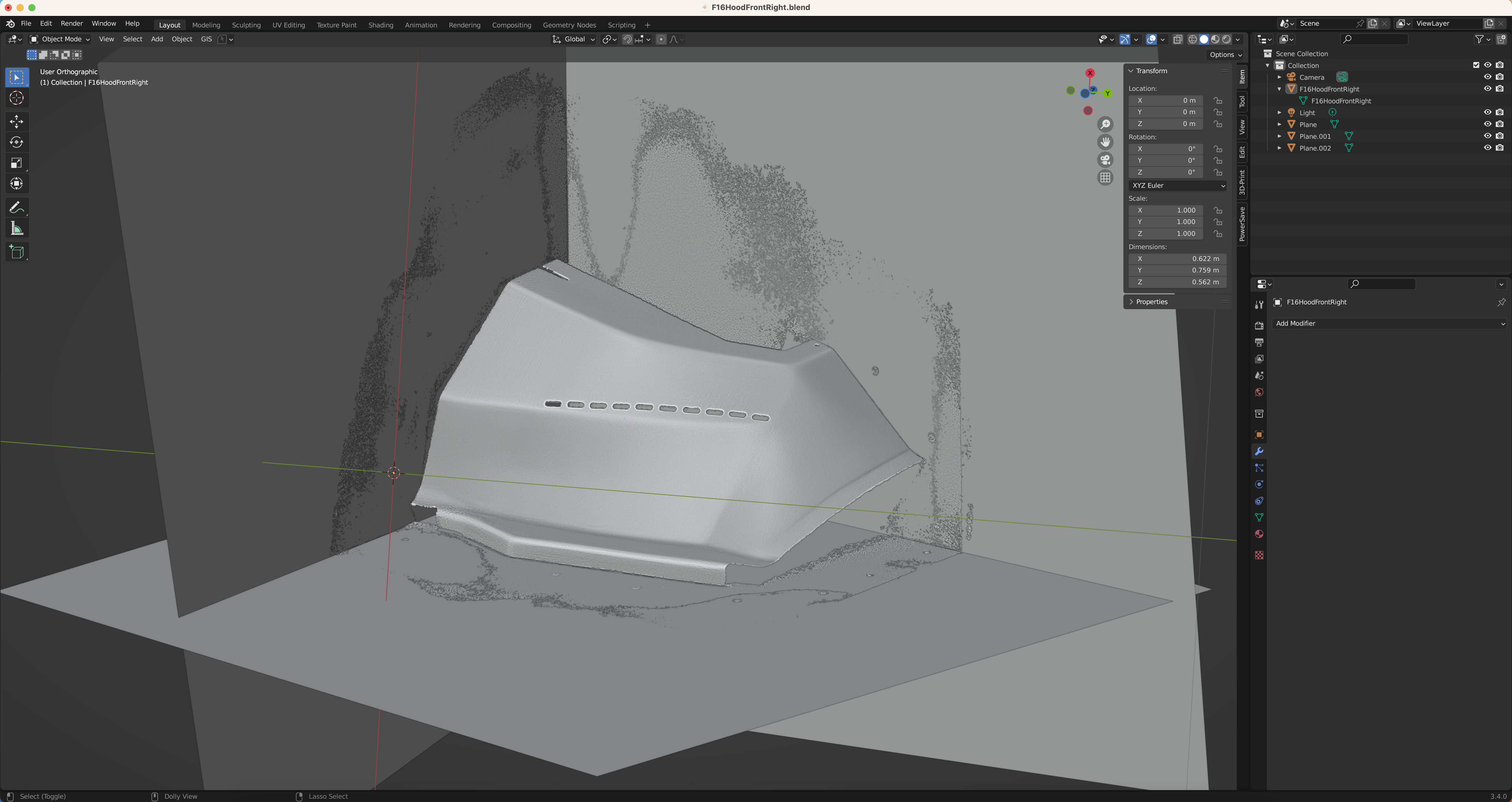
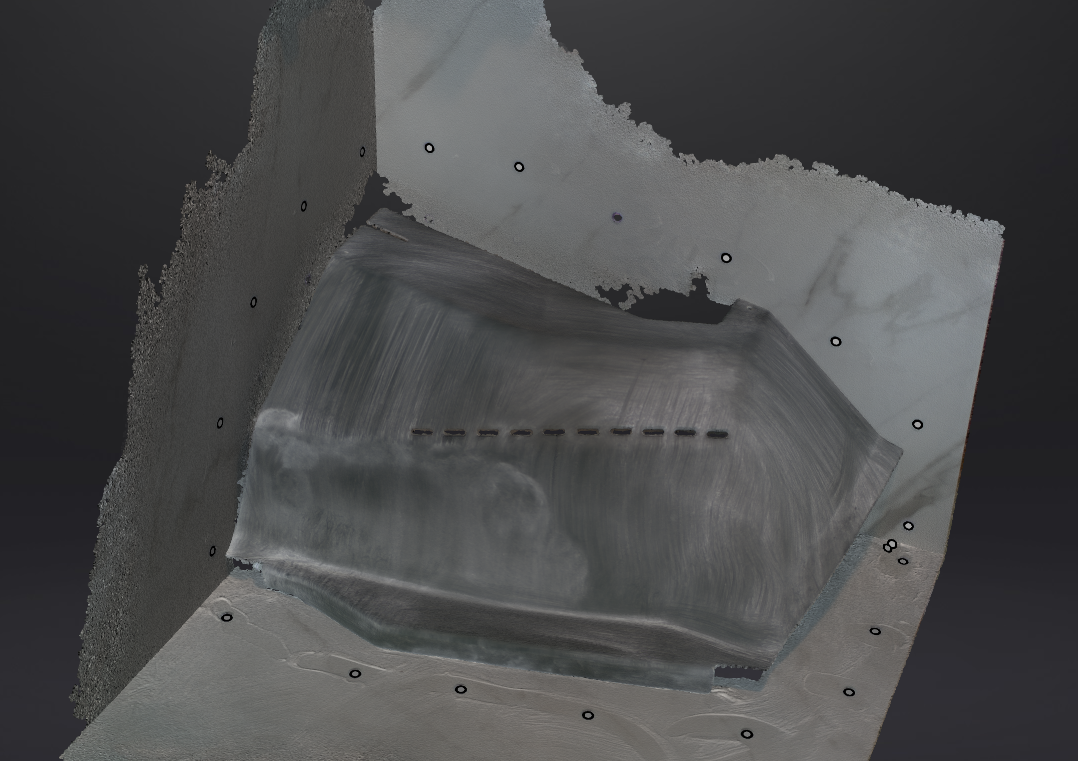
Another scan... this time I put on some dots to help on the scanning of the 3x walls. This is the textured scan (not a picture). Basically, it's a screenshot of what I see on the scanner software after the texture is applied to it. You can even see my finger wiping the powder away to apply the dots. And you can see I have too much powder. However, now the scan quality indicator on the walls are pretty green! Next scan. I will have to either watch the powder or switch to AESUB spray. null
-
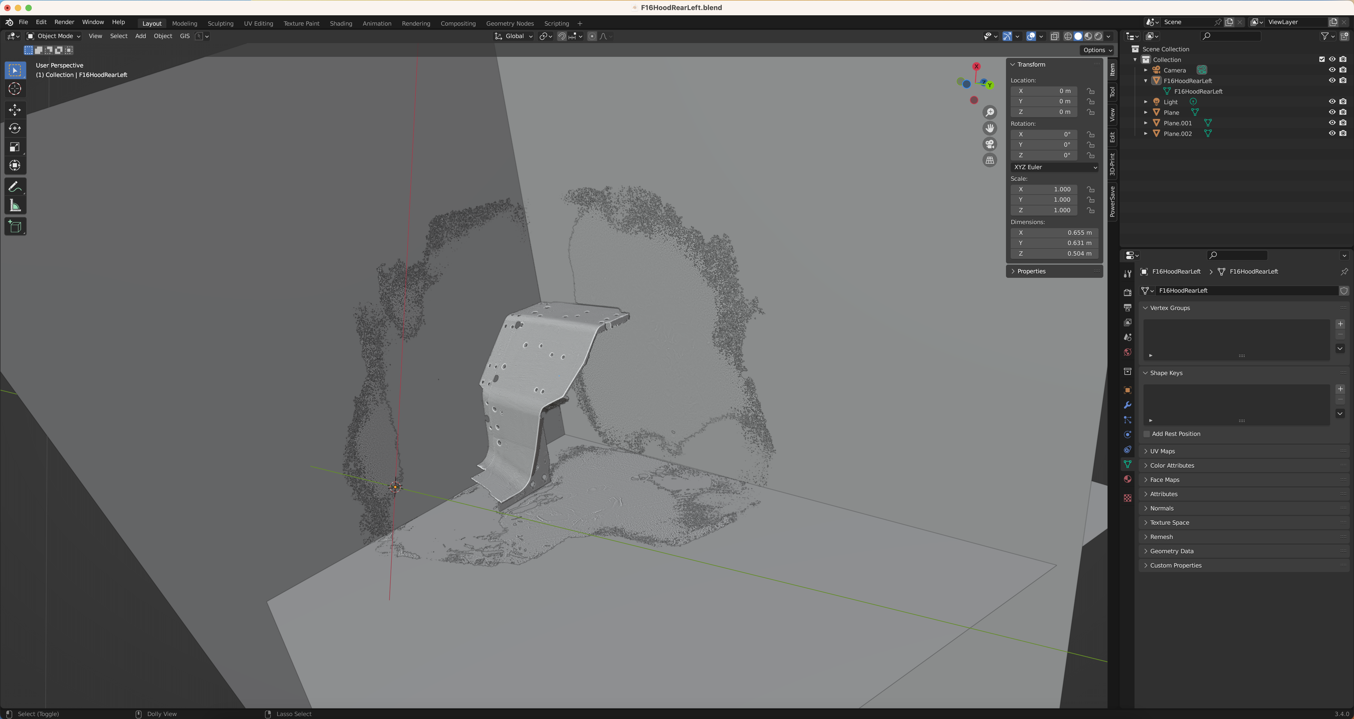
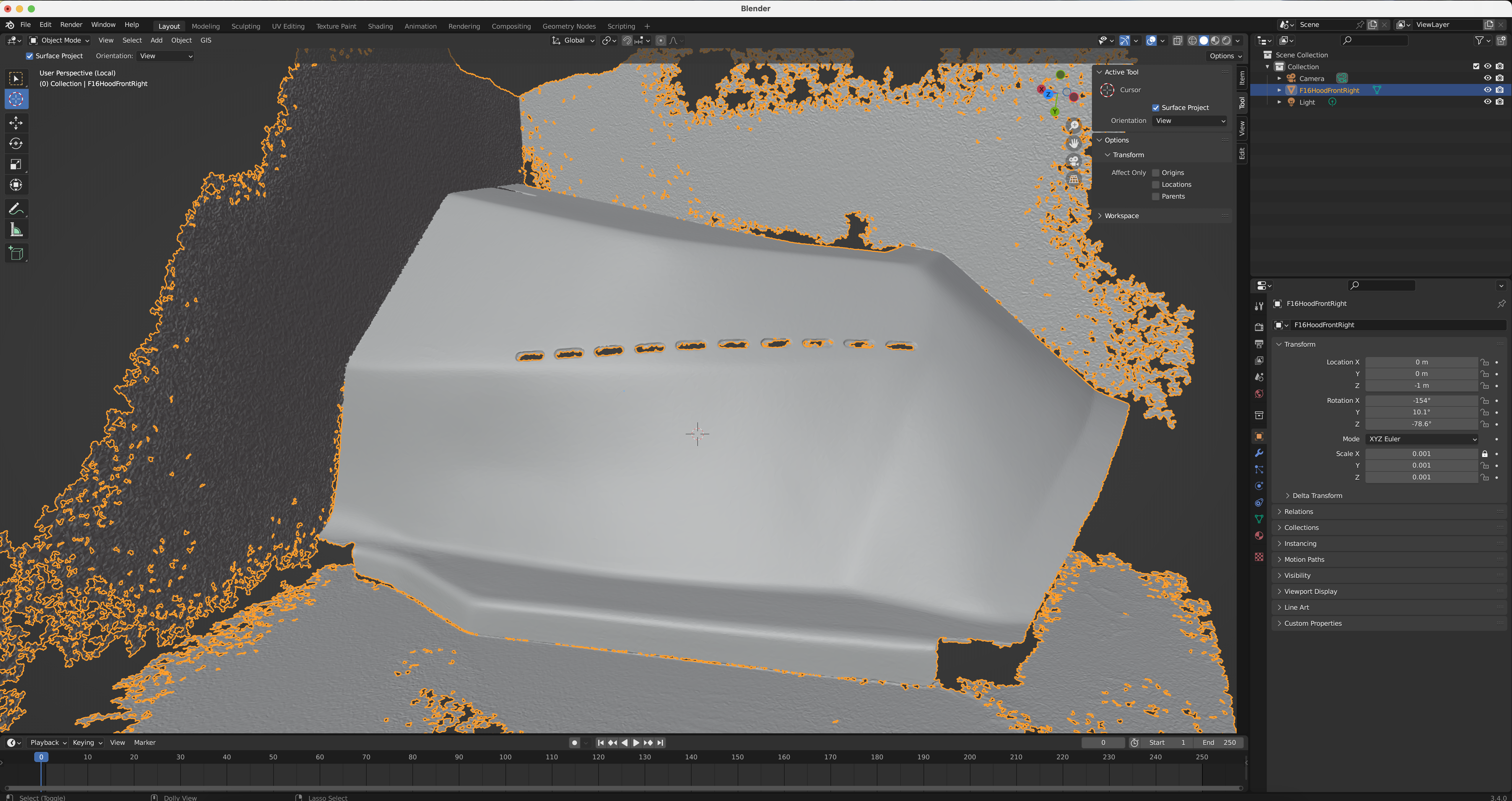
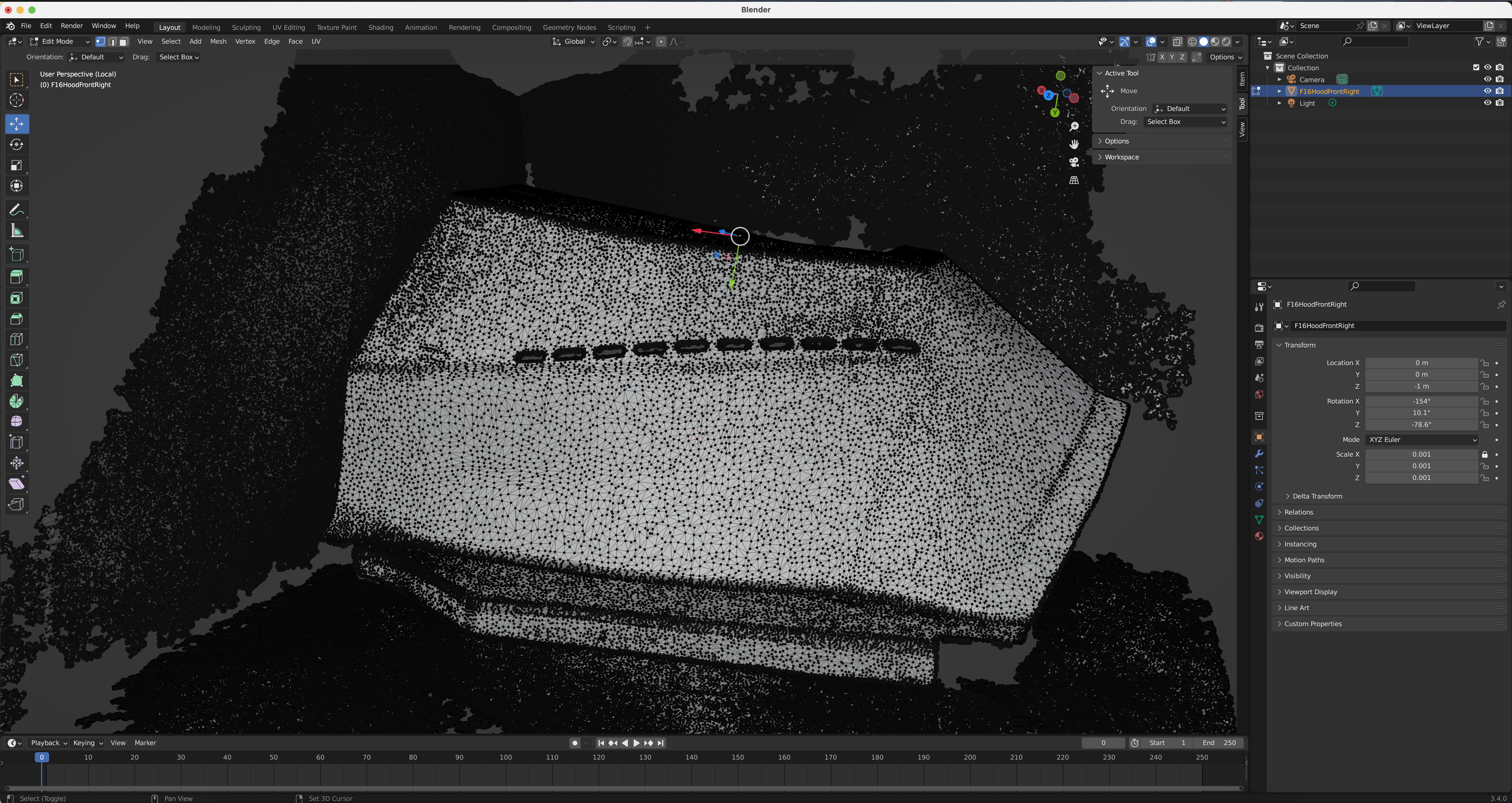
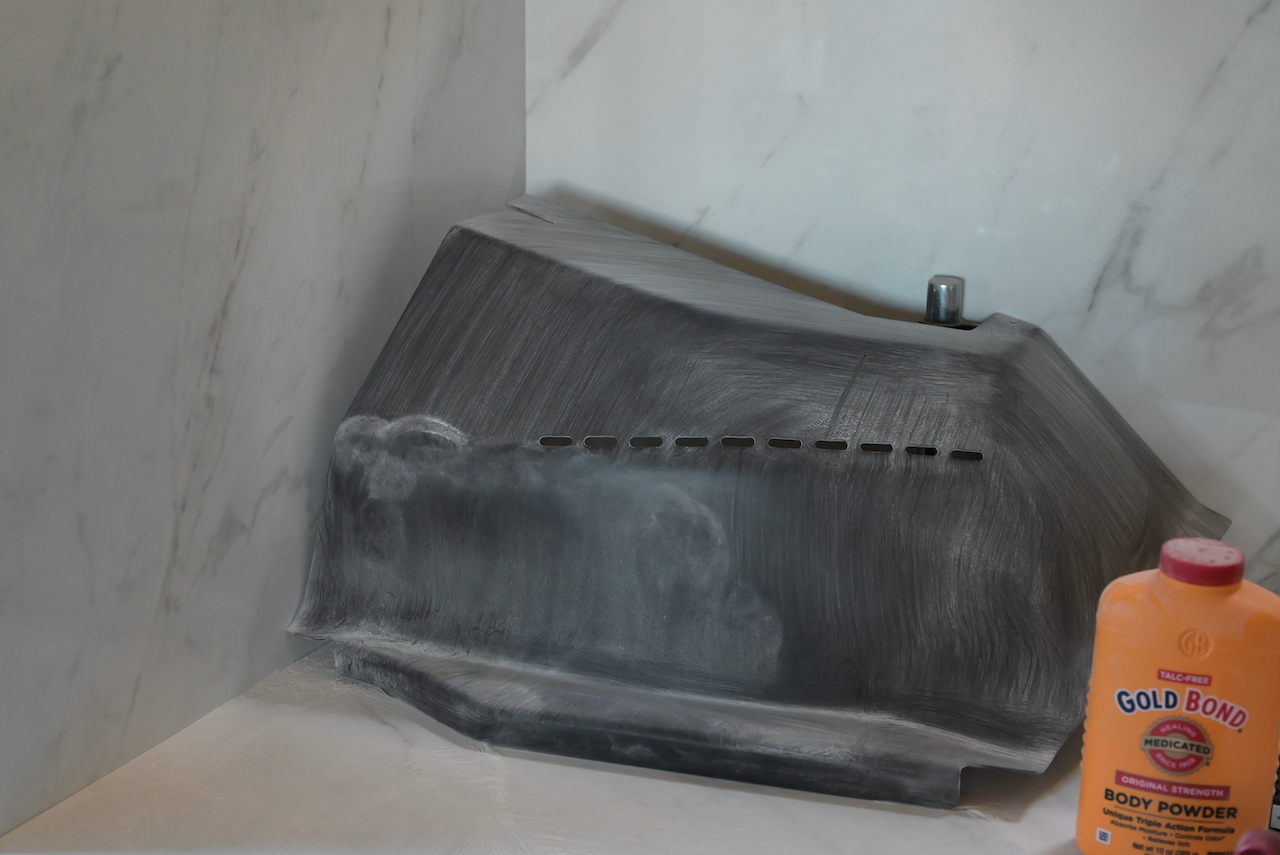
Ha... didn't even need to use global dots. Although the scanner software was complaining about the 3 "walls" need global locating dots (the scanner uses IR, so it needs reflective dots, not just plain black/white dots.) Instead of standing it up vertically like in the picture I posted a couple of days ago, I am laying it down (propped up inside with a machinist gauge stand) butting against the floor and the far rear wall. This is for two reasons: 1. I know exactly the angle for the left plane and the bottom plane (10 degree). So, from the bottom plane and the rear plane, I can derive the left plane. 2. Most importantly, instead of using the expensive AESUB spray (great product by the way, highly recommended), I am using the much cheaper and messier Gold Bond body powder. Gold Bond powder doesn't stick too well on vertical surfaces... it kind of... but easily disturbed, and difficult to dust evenly. So, I bought a baby powder puff for that.... kind of works. But now I have a mess on my hand. Oh well... Now I just have to figure out a way to make it comply to my will in Blender. I could cheat from here on... like I already know four of the most important clamping planes to constrain the geometry in (the 4th one on the top is just 10 degree off against the bottom, and the right plane is not exactly important, precision wise). So, I could just import it into SolidWorks, construct the 4 planes, and start slicing to get section. contour curves and force the geometry into the clamping planes. Sure, there will be inaccuracies. But how much? I suspect it will be very little. The thing is... for this particular piece, the 4 clamping planes are the "interface" that connects to other pieces, where the accuracy is required. The free form curved surfaces.... Nah... not really, precision without too much off accuracy would be good. However, this scanning project is more of a explorative nature. So I will try coax more accuracy out of it and figure out what tools are needed to do so. The mesh you see in the following pictures is decimated to about 1,000,000 vertices, in case you are wondering. 500,000 vertices seem a bit "rough." It picked up the brush strokes on the powder as some undulating geometry (wasn't in the pure point cloud, or I couldn't see it in the pure point cloud without the connecting edges). No good. And this decimation, from the scanner software, doesn't seem too bad. It gives more vertices on the bend radius where it's needed, and kind of eventually distributed the vertices across flatter surfaces. So it appears that it does consider the curvature k in the decimation algorithm. Not too bad, not too dumb. But unfortunately it takes a very long time to run the decimation. 10 CPU cores / 20 threads fully 100% engaged took about 20 minutes (compiles Linux kernel arm32 in about 68 seconds with 20 threads!). Thank goodness my CPU is water cooled with an oversized 3 fans radiator; it can do 100% on 20 threads all day long without over heating! A couple of global locating dots would probably help the walls (quality indicator on the walls are mostly yellow instead of green on the artifact). Nah... I will probably get away with it. Gold Bond powder and reflective dots are not very good bed fellows.
-
https://github.com/JonahTsai/F16
-
Has the Open Beta Just Switched to OpenComposite?
Hempstead replied to Hempstead's topic in Virtual Reality
It was a question.... note the question mark. Although I admit, I was tilted to the OpenComposite assumption. You'd be surprised how much OpenSource stuff is integrated into commercial products.... even if you exclude the obvious stuff like RedHat Linux, and all kinds of Linux distros. Today, all kinds of OpenSource libraries are linked into commercial products, even your PS5 OS comes up with quite a page of copyright notification featuring a huge number of OpenSource software. Don't you know Windows 10's WSL (Windows Subsystem for Linux) now is a Ubuntu distro VM? Also, the SSH distro in Windows, via add/remove software, is now an OpenSSH. > ssh -V OpenSSH_for_Windows_8.1p1, LibreSSL 3.0.2 -
This is the concept of trying to coax more accuracy out of "toy grade" 3D scanners. Ok... how? First, we must describe what the problem(s) I am trying to solve, then we will describe the conceptual solution. The main things I am observing is the followings. 1. The scanner sees only a partial view of the whole article to be scanned. 2. It seems to have local precision and accuracy... although they seem to confuse accuracy with precision, let's just say I suspect it has both accuracy and precision at something like sub-mm, be it 0.2mm or 0.5mm. In other words, let's "assume" it has local accuracy and precision with one "view." 3. It runs something similar to SLAM and "localize" its location, most likely with help of on board IMU kinds of sensors but use SLAM to do things similar to pattern recognition to match different views at runtime.... But... either this "localization" has errors or there are accumulated errors from views to views... so I have observed that two parallel surfaces like the two sides of the F16 stick base... depending on the path of your scanner, the two faces could end up not parallel... if I scan from the round cylindrical face direction going from one side wall to another side wall, they could end up like at 30 off. 4. Even if scanning paths is carefully selected to minimize the errors, the end result of faces that are supposed to be perpendicular to each other might be 2 or 3 degree off. The Possible Solution In the picture, you see the rig is made out of 3x 2'x2' ceramic tiles (just marble pattern). The reason for select ceramic is for its rigidity -- less warping. Then, they are clamped together with wood working corner clamps, forming a corner... hopefully as close to perpendicular to each other. I am going to stick a lot of 3D scanning dots on these three surfaces... and use them as global locations. So the scanning paths will be carefully selected to have these "global" dots in each view as much as possible. So, once the scan is done... I can go into a mesh program, either in Blender or SolidWorks, and averaging and fine the 3 perpendicular surfaces... and use them as handles to "twist and distort" the whole thing back. That is, the 3x perpendicular surfaces now serve as my Book Endings to limit the errors and they are the reference surface to restore some of the accumulated errors. Of course, in reality, the 3x surfaces are not going to be 100% perpendicular... but all I need is them to be within an acceptable tolerance. Or, I can measure the angles among them, and "twist" them back in the model accordingly. I wish I could find matte surface tiles... unfortunately, no such luck. So, I will have to paint or spray the surface with something matte, or the permanent AESUB spray I have (not sure how durable that spray is, the white can). Wish me luck!