Hempstead
-
Posts
473 -
Joined
-
Last visited
Content Type
Profiles
Forums
Events
Everything posted by Hempstead
-
This is the concept of trying to coax more accuracy out of "toy grade" 3D scanners. Ok... how? First, we must describe what the problem(s) I am trying to solve, then we will describe the conceptual solution. The main things I am observing is the followings. 1. The scanner sees only a partial view of the whole article to be scanned. 2. It seems to have local precision and accuracy... although they seem to confuse accuracy with precision, let's just say I suspect it has both accuracy and precision at something like sub-mm, be it 0.2mm or 0.5mm. In other words, let's "assume" it has local accuracy and precision with one "view." 3. It runs something similar to SLAM and "localize" its location, most likely with help of on board IMU kinds of sensors but use SLAM to do things similar to pattern recognition to match different views at runtime.... But... either this "localization" has errors or there are accumulated errors from views to views... so I have observed that two parallel surfaces like the two sides of the F16 stick base... depending on the path of your scanner, the two faces could end up not parallel... if I scan from the round cylindrical face direction going from one side wall to another side wall, they could end up like at 30 off. 4. Even if scanning paths is carefully selected to minimize the errors, the end result of faces that are supposed to be perpendicular to each other might be 2 or 3 degree off. The Possible Solution In the picture, you see the rig is made out of 3x 2'x2' ceramic tiles (just marble pattern). The reason for select ceramic is for its rigidity -- less warping. Then, they are clamped together with wood working corner clamps, forming a corner... hopefully as close to perpendicular to each other. I am going to stick a lot of 3D scanning dots on these three surfaces... and use them as global locations. So the scanning paths will be carefully selected to have these "global" dots in each view as much as possible. So, once the scan is done... I can go into a mesh program, either in Blender or SolidWorks, and averaging and fine the 3 perpendicular surfaces... and use them as handles to "twist and distort" the whole thing back. That is, the 3x perpendicular surfaces now serve as my Book Endings to limit the errors and they are the reference surface to restore some of the accumulated errors. Of course, in reality, the 3x surfaces are not going to be 100% perpendicular... but all I need is them to be within an acceptable tolerance. Or, I can measure the angles among them, and "twist" them back in the model accordingly. I wish I could find matte surface tiles... unfortunately, no such luck. So, I will have to paint or spray the surface with something matte, or the permanent AESUB spray I have (not sure how durable that spray is, the white can). Wish me luck!

-
It looks like the new Open Beta is shipping with OpenComposite's .dll. Is this true? Ok... I had OpenXR Toolkit installed... for MSFS only. I never replaced the OpenComposite dll in DCS. But now after updating to the latest DCS OpenBeta. Suddenly, OpenXR Toolkit's prompt showed up asking me to press Ctrl-Down to bring up the menu... sure enough, Ctrl-Down, and OpenXR Toolkit's overlay menu showed up. Or perhaps there is a new OpenXR implementation for Oculus, i.e. does not use the old Oculus API, but uses the new OpenXR API directly for Oculus devices? I don't see this mentioned in the OpenBeta release notes.
-
TM is THE joystick company that pioneered post sale supports. They were the only company that would sell you parts to repair your controllers. Now there are more companies doing the same, TM still will sell you parts. Not cheap, mind you. Plus… please, the long text description is very difficult to understand. In this situation, a picture indeed is worth a thousand words. How about a picture with a red circle?
-

Did anyone ever tried this with the Warthog slew "nipple"?
Hempstead replied to sirrah's topic in Thrustmaster
It’s not the size, whether you are talking about a nob or a stick…. *snigger* Well, give it a try. Just don’t drill more than 3mm. -
Did anyone ever tried this with the Warthog slew "nipple"?
Hempstead replied to sirrah's topic in Thrustmaster
I don't think longer "lever" is going to help you. Because.... it's not a gimbal type mechanism under there. Under there, it's an AMS package Hall sensor module, which has the mechanism similar to the PSP joystick... it slides in both X and Y directions on a flat plane. The AMS Hall sensors senses displacement, not rotational angle. Since it's a slide mechanism, there is no such thing as a lever, hence no such thing as a "longer" lever to increase the rθ arc length. The longer "stem" just increase the torque load and gains you nothing else other than the torque induced friction. -
Oculus Pro controller attachment with a rubber sleeve.
-
Hmm.... the thumb strap is interesting.... I got to make one and try it out...
-
Nothing new, just reposting what I posted somewhere else about my MonkeyOnTheBack attachment. Here's the BOM for my mod: DesTek Quest Pro Sleeve: https://www.amazon.com/dp/B0BGN3XLG4?psc=1&ref=ppx_yo2ov_dt_b_product_details 0.75” quick side release buckle: https://www.amazon.com/gp/product/B09DY14TJ8/ref=ppx_yo_dt_b_asin_title_o05_s00?ie=UTF8&psc=1 polypropylene Webbing: https://www.amazon.com/gp/product/B01KTVCZAM/ref=ppx_yo_dt_b_asin_title_o06_s01?ie=UTF8&psc=1 With the sleeves, you don't need to drill holes... but if you don't use sleeves for Quest 2, you'd have to drill two holes on each battery cover... and make a wire loop for the webbing. I use some aviation stainless safety wire for it. You don't want to use 1" webbing... too wide... cutting into your palm. 1/2" too narrow... wobbling more than 3/4". I tested all of them so you don't have to.
-
Here's the BOM for my mod: DesTek Quest Pro Sleeve: https://www.amazon.com/dp/B0BGN3XLG4?psc=1&ref=ppx_yo2ov_dt_b_product_details 0.75” quick side release buckle: https://www.amazon.com/gp/product/B09DY14TJ8/ref=ppx_yo_dt_b_asin_title_o05_s00?ie=UTF8&psc=1 polypropylene Webbing: https://www.amazon.com/gp/product/B01KTVCZAM/ref=ppx_yo_dt_b_asin_title_o06_s01?ie=UTF8&psc=1 With the sleeves, you don't need to drill holes... but if you don't use sleeves for Quest 2, you'd have to drill two holes on each battery cover... and make a wire loop for the webbing. I use some aviation stainless safety wire for it. You don't want to use 1" webbing... too wide... cutting into your palm. 1/2" too narrow... wobbling more than 3/4". I tested all of them so you don't have to.
-
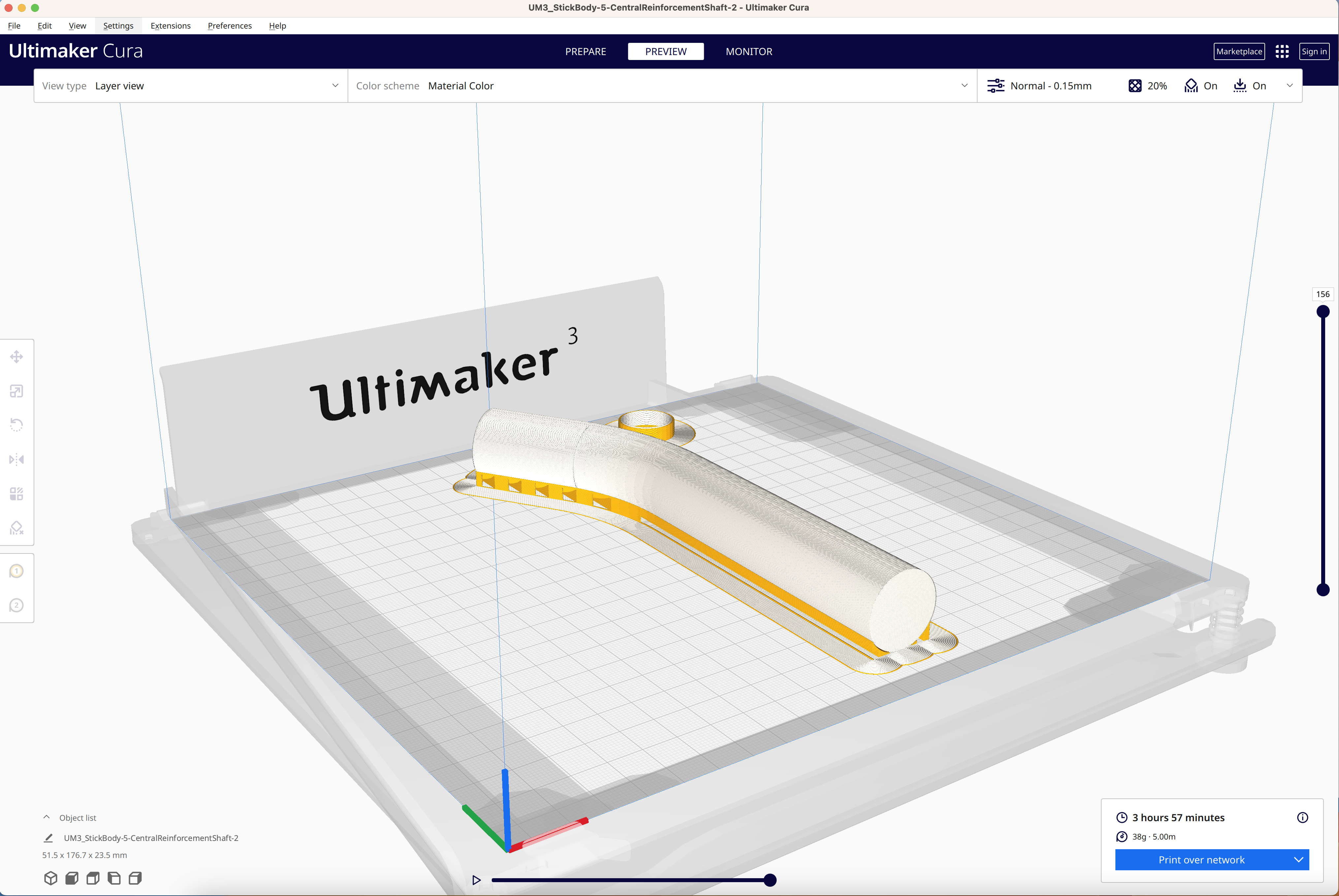
While the other half of mold is being printed.... Got a new idea. The original idea was to print a negative mold of the shaft, then take a woven carbon fiber sleeve, stick it inside (3 layers, I think)... and epoxy up, put on release film, and absorption mat, and outer plastic tube bag through the middle, fold back and wrap around outside of the whole mold... then vacuum/seal. Sure, theoretically it will work... it's just that... practically, that OD=1" - 0.4mm tube is a bit difficult to apply epoxy from the inside and then do all the other things... so the idea was to pre-apply epoxy resin on the fiber sleeve, fold over twice, and epoxy the mold, and do all the other things.... Sure... still a pain. So, what if I print the negative tube inside with the Breakaway material? I just have to adjust the negative tube's diameter to compensate for the thickness of the carbon fiber epoxy layers... Well... the OD will not be precise... But so what? Wrap some tennis racket anti-slip tape and then screw it down inside to compress it tight. Or, worse comes to worst, epoxy the whole damned shaft inside the stick body, permanently. Sure, that will make the assembly of other buttons/HAT a big harder... but not impossible. Maybe... I can take the breakaway plug, apply release agent, wrap chopped carbon fiber around, epoxy, then apply release agent on the mold, then screw down... making it a forged carbon fiber composite? Or use woven carbon fiber sleeve still? This way, I have best of the both, accurate OD, and still easy to make. Just have to make sure the infill is not too dense making tear it out a PITA.
-
Oh… I have Blender… for me, it’s now the new king of mesh based creation, and editing, and much more. I even bought a Wacom tablet specifically for it. Ok, that was my excuse, and I am sticking to it. I don’t think review of scanning methods would help, I keep taps on them anyway. The troubles I am encountering are just typical of the Maker movement… does it work? Sure. But how well does it work? What do you mean? It works, see? These Chinese cloners basically have a similar mentality - quickly make something work to make profits, but do not go through the time consuming and costly validation process to verify how well their products work. To their defense, these are not industrial products… and never advertised as one. They are toys. Perfect for scanning and printing bubble heads. I just didn’t know they would all be this trashy, even from a “big” company. The question is, is it possible to make use of these toys in a manner that is useful to my requirements. No worry, I think I have figured out a way to correct some of distortions and accumulated errors…. theoretically. It’s just that I will have to build a specific scanning rig to help me correct the problems I observed in the manual reverse engineering process. We will see how well that works out, once I received the parts I ordered. There are good reasons why some “real” scanners cost tens of thousands of dollars apiece. But, hey, at least this new scanner finishes the scanning process, unlike my older one which crashed all the time and rarely got me any usable scan. If I succeed in coaxing some accuracy out of the toys, I will let you guys know.
-
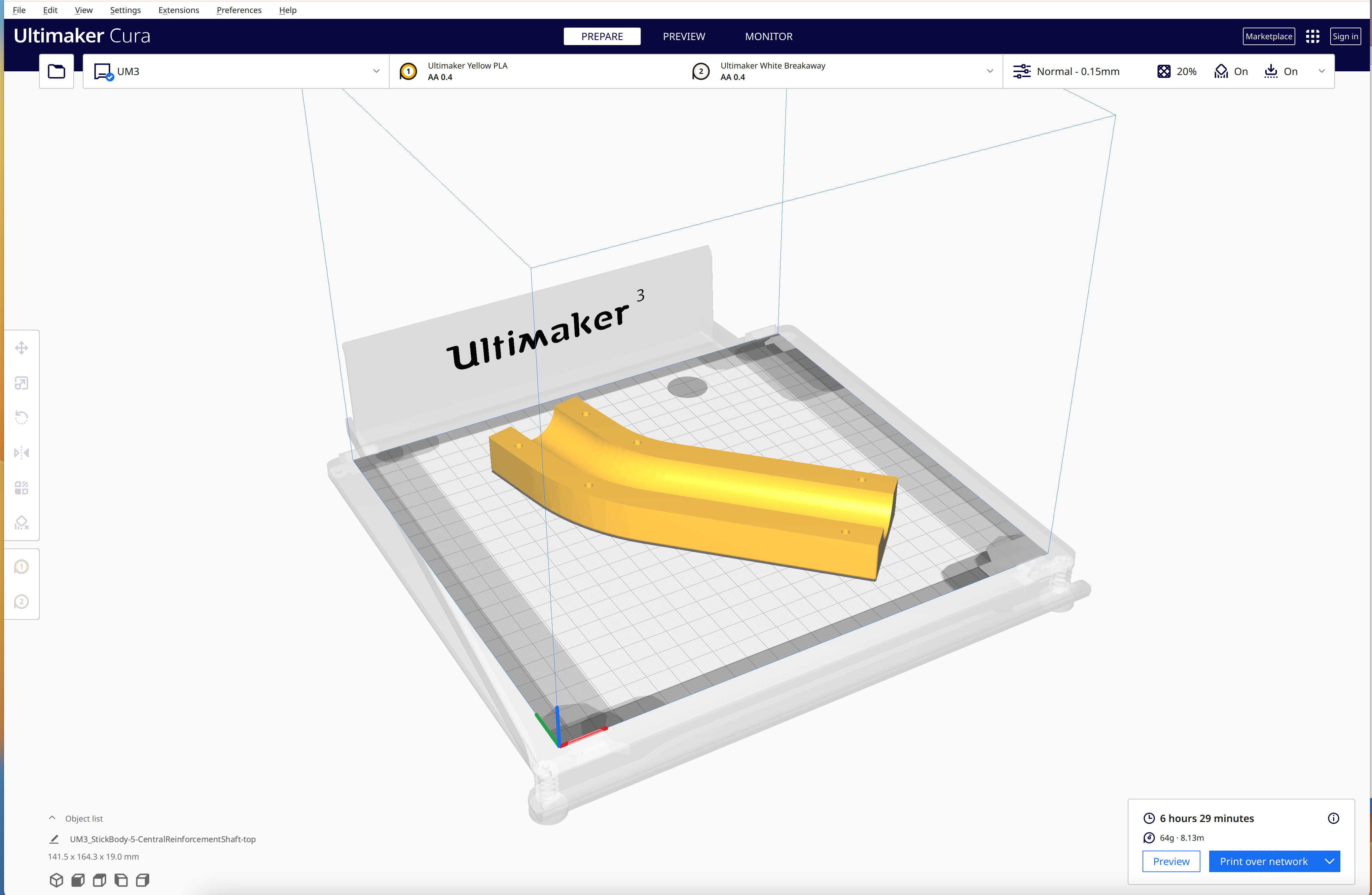
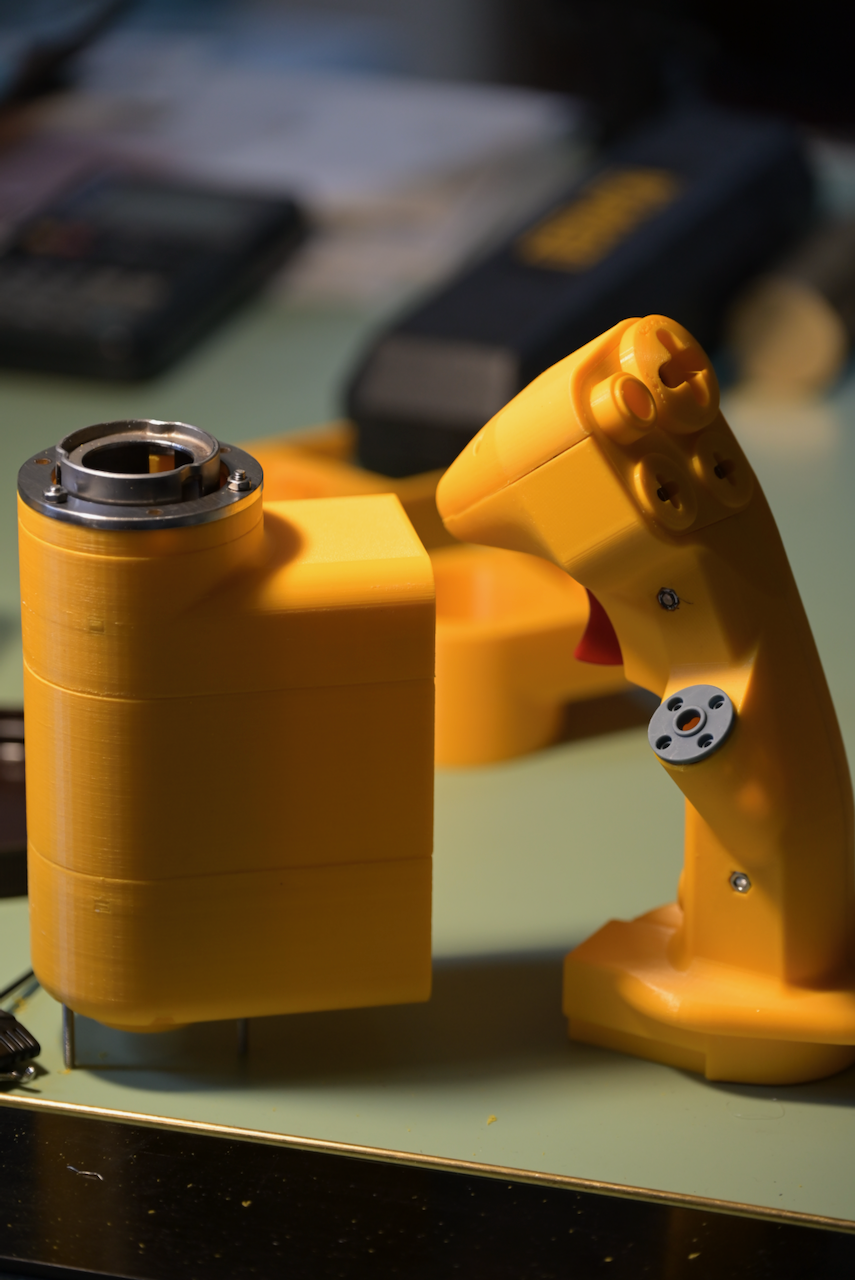
I have decided to try making the control stick shaft with carbon fiber composite. So, I designed a split mold for a woven carbon fiber sleeve with vacuum process. That's half of the mold in the picture with "normal" profile....
-
These Chinese made scanners are disturbingly inaccurate! The scanned models might look just right, nothing matches when I tried to reverse engineer them manually in Solidworks! Ha! Automated scan to 3D would have GIGO! The angles are here 2 degree off, 3 degree there. My guess is that they have local accuracy, but the accumulated errors add up. They either don’t understand the underlying engineering principle, or they don’t care, or these are consumer grade “toys.” I will have to find some way to inject correct dimensions and angles to “twist” them back to match without introducing too much inaccuracies, i.e. inaccuracies at where it doesn’t matter.
-
I use this mod. I got so used to it that I use it to control everything on the F16, except HOTAS, rudder, Alt. Hold, and gear up/dn. Even rotaries work quite well. I even fly my DME Arc with it, which requires adjusting the course dial on the HSI frequently. I have the laser pointer on, and the laser only turns on when I hold down the palm button. The palm button activation is necessary, b/c otherwise when the controller is hanging right next to the throttle, it’s quite easy to hit the gear down accidentally. With the new Oculus Pro controller, drilling two holes for running the wire through is quite difficult without fully disassembling the expensive controllers. So, I bought a pair of rubber sleeves for the pro controller and hang them the same way.
-
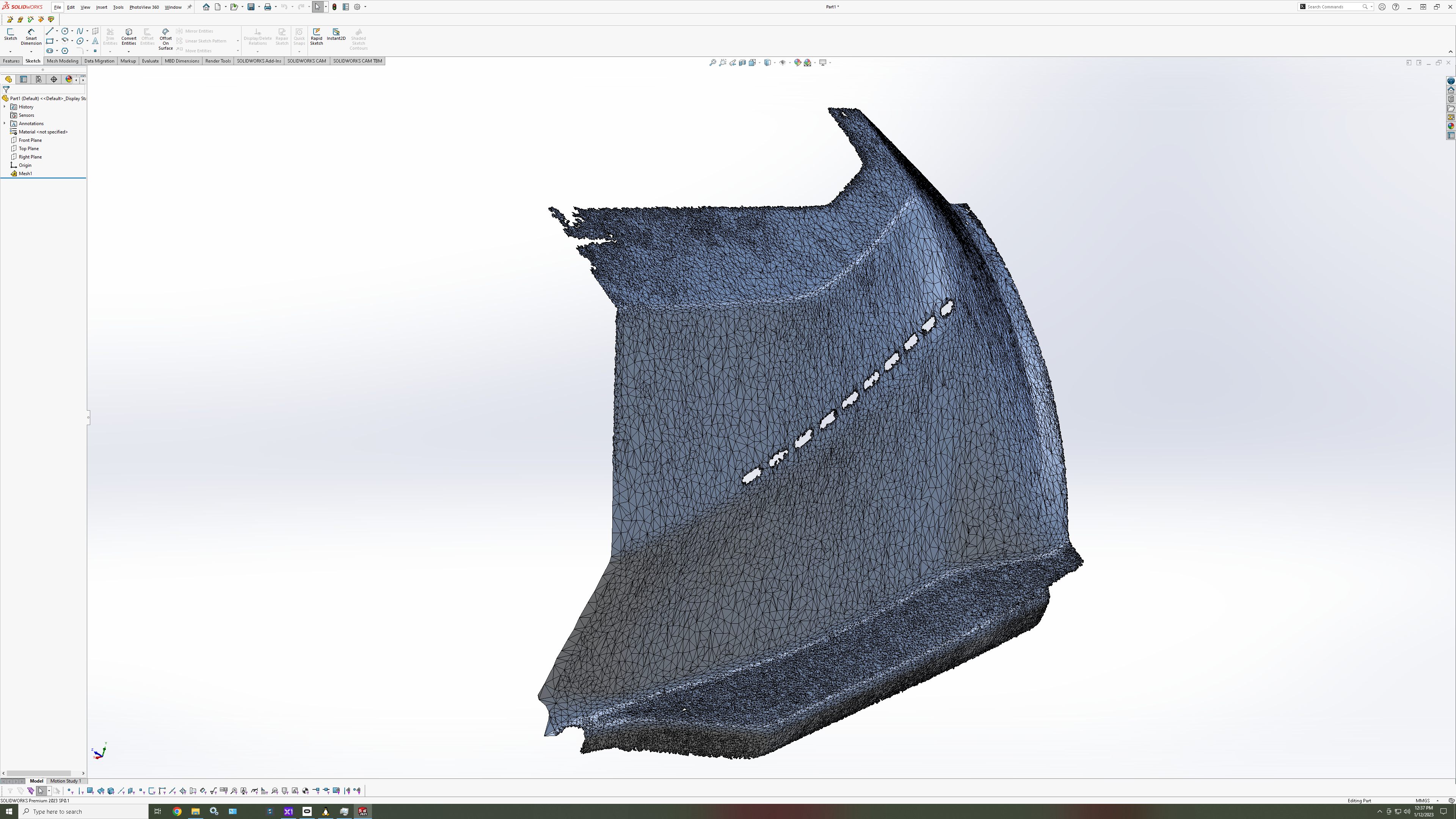
The following is a screenshot of decimated first with scanner vendor supplied software, then used Solidworks' ScanTo3D to import. I want the high resolution of the coordinates, not the high resolution of more mesh triangles. Probably could use Blender to decimate and fix the mesh as the in between processing step. Blender is designed to deal with meshes from the start. Solidworks... nope, although it has improved tremendously in the last 10+ years, it's not what it's good at. 50K should be plenty enough (actually way too many already) to use as the basis for reconstruction in solid.
-
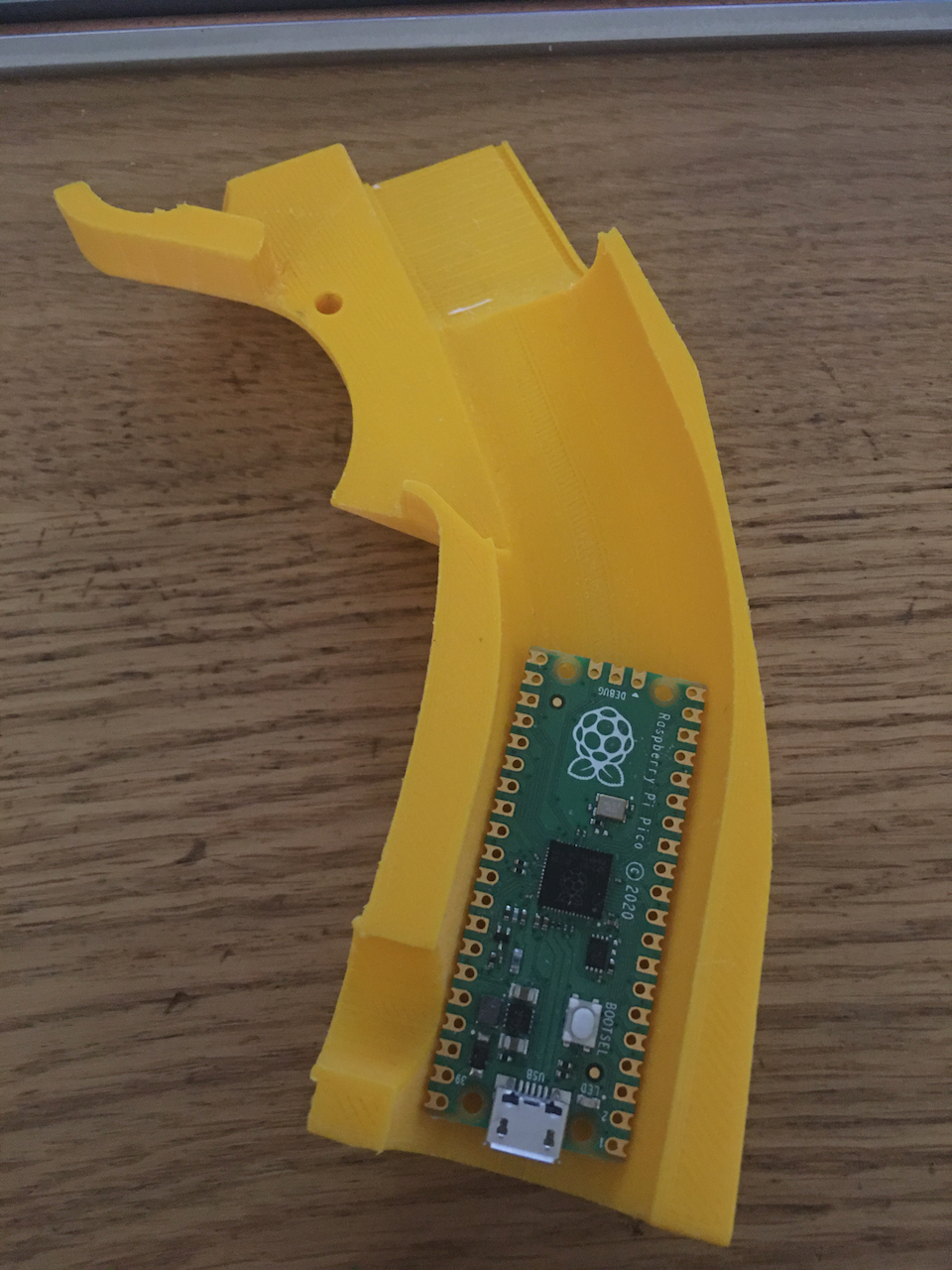
Pico is going to use Raspberry Pi Pico board, just USD$4, Pico W $6. And they are dual core, 133MHz. Most likely I will force it to be Pico W, so it has network ability for configuration, and perhaps communicate with other non-real-time controllers and form a cockpit mgmt system (I have already chosen which system to use, but not telling yet.) The force sensor I chose is about USD$30 apiece. Other parts are mostly 3D printed and off the shelf stuff, like a couple of screws, nuts, etc. The right sized spring is a different story… expensive for quantity of 2. But essentially, it's using springs and force sensors to simulate hydraulic feel. I may ditch the 1st stage spring to simulate the “before contact” spring feel. Total cost, still way cheaper than a motorcycle hydraulic brake assembly I bought for testing.
-
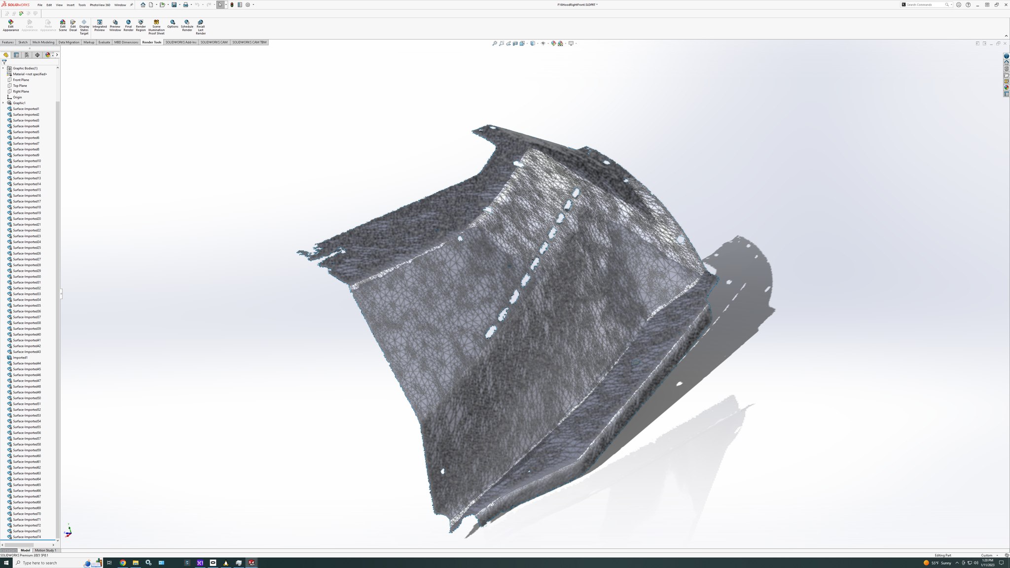
From my new 3D scanner. Imported into Solidworks, decimated from something like 5.6 million triangles to about 100,000, then converted to mesh model. I still yet to convert it (manually, instead of automated) into a solid. And yes, I do have the other 3 pieces.
-
One thing to mention so people don't get the wrong expectation. The Hempstick Pico will be designed only for high speed, low latency operations, like the control stick, throttle, and rudder. Unlike the original Hempstick, which was designed for high speed, low latency, but with an eye toward expandability toward all instruments in the cockpit. Hempstick Pico will NOT be designed for general purpose cockpit instrument controls. For instance, most likely it will mandate that all the switches/buttons used require no software debouncer, or have hardware debouncer. That is, if you hook up a toggle switch to be the missile fire button... it might fire 5 missiles at one press instead of just one. I most likely will not implement software debouncer that degrades the latency. For general cockpit controls, like caution panel, steam gauge altimeter, ICP etc.... I am working on something else, like the following video. They will run regular RPis, with full Linux, and something else that I am not telling yet. It may not be RPi4, it most likely will be a fleet of RPi Zero 2 Ws, plus a few RPi 4s (ICP and the two MFDs use one RPi4, but the caution panel can just do fine with a $15 RPi Zero 2 W.). In other words, Hempstick Pico will not be a pig that does everything badly. The other one will be the pig.
-
Nah... the hydraulic feel is slightly different from simple spring. The first part is the simple spring... then, when it hits, i.e. the brake pads contact the rotor, it then becomes similar to force sensor, but not quite. A pure force sensor would be like hitting a hard surface... abrupt stop. But it's really like it gradually switching to a very short stroke strong spring, like the hydraulic hoses would expand slightly, so the piston will go slightly in a tiny bit. Now, this tiny bit then gets amplified by the level length of the brake pedal... so, it's not exactly a strong spring, nor is it a straight force sensor / load cell... So, I plan to simulate it with a force sensor, but with a strong 40lbs 1" spring (paid an arm and a leg for the low volume to Lee Springs). Then, perhaps I will add a longer stroke, but much weaker spring to simulate the "before" stroke. It's not a high priority task... because DCS's F-16 brake is a bit crappy... does it even have differential brake? I couldn't tell. Plus.... the toe brake part of F-16 is a low priority thing to begin with... so, it has a low priority of low priority ranking on my job list.
-
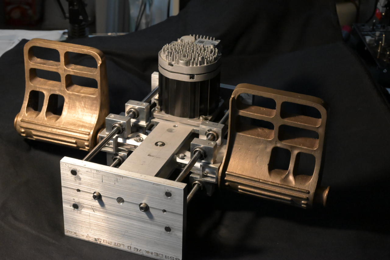
In case you have never seen it. This is my RudderCore prototype. Please note that I no longer use the central pivot bar (requiring CNC milling, but could be made by hand if you are very skillful). The pedals are bronze casting. I made it myself with the tried and true Lost Wax process. Why bronze? Well... I took some bronze casting class at a local arts institute. Artists do bronze... they don't do aluminum. Since this thing will fly at exactly 0 agl... weight isn't a consideration at all. The motor on top is an industrial servo motor serving as my "force generator." That motor itself is something like USD$400+, and there is a USD $150+ power supply (not shown). Except the pedals, all of the parts can be bought or made at home with just some simple hand tools and some basic machinery, like an el cheapo drill press.... but some would benefit with a milling machine (for instance, the central bar with motor mount... you could made it one piece by jig saw for hours, or you can mill it, or you can make it out of two pieces and bolt them together). The anti-torque rail mount... there is one part that would be a bit difficult to make by hand, but if you are patient, you can just use a hand file instead of a milling machine (maybe 10 minutes filing apiece would do it; you need two). What's missing are: 1. the Hempstick Pico to read the hall sensor and then drive the motor accordingly. 2. My design of force sensor... for the toe brakes. I have the design, and some prototype parts, but not completely done yet... some modifications still needed. Why force sensors on toe brakes? Well... to simulate the feel of hydraulic, of course... kinda... I bought some hydraulic brake assembly for motorcycles... didn't like the heavy heavy sticktion at all.
-
Well, in that case. I will answer both. Yes. I bought a Bodnar board years ago. I found it….. average. 1. 12 bit ADC. Pretty much every MCU made after 2010 have 12bit ADC(s), if it has one at all. So, unless you are using already outdated MCU when Arduino was first designed…. You’d have 12bit. So stay away from those Arduino boards using AT90xxx or ATMegaxxx MCUs. 2. Not a clue what the sampling rate is, advertised or real. 3. no provision to do MLX hall sensors, or anything like that. You can only do analog ADC at your native ADC resolution. 4. no possibility to do force sensor…. my way. The last two are the killer that drove me to write my own. Arguably, I never achieve #3 fully with the original Hempstick, but I did the configurable oversampling to go up to 16 bit. I did have a partial MLX90333 digital mode code, but lost that in an HDD crash. #4… I never started. Not that I had a design to test on at that time. But, now I have 2, rudder, and stick. Hence, the idea of Hempstick Pico to do it all. Also, Bodnar board is a general purpose joystick board. It’s market is in general purpose joysticks. It does not do anything special like, read a TI Delta-Sigma ADC, which is hooked up to two force sensors for toe brakes. Even though it later tried to be a bit more modular and expands its market to load cell boards, it’s still a general purpose load cell module. I chose that TI chip to drive the specific force sensor I chose. It’s not possible for Bodnar to anticipate. That is, if you want to go off the beaten paths, you have no choice but to do it yourself. But, if you are staying on the trodden paths others have already gone before, Bodnar board is a good choice. It works for what it’s designed for, general purpose joystick, and it works well for that. It’s just that I am not doing any run of the mill thing at all! Now, look at what I have shown you from the RudderCore, to the stick base 2, to the faux F-16 stick, to the optical sensors, to the Hall Mini Stick, which one is on the beaten path? Which joystick firmware is capable of using force generation to create force curve (think electronically programmable CAM, instead of mechanical CAM pioneered by Milan; and I have ideas that go beyond just simple CAMs). There is just no such thing in existent…. I have no choice but to write it myself. Ask yourself this question, do you design something that a Bodnar board can’t do? If not, then use a Bodnar board. If yes, consider modifying an Arduino joystick firmware. Suck as they are from a software engineering PoV, they do work! The question is how well do they work? Well, if you don’t know how well “what” work, then it doesn’t matter to you anyway. No offense, if you want to use an external ADC to get higher resolution, which Bodnar board can’t do. Then you got one question and one solution you can ask that dreadful question. If you care about stable sampling rate, then ask how an Arduino busy loop can satisfy that. Don’t wait for the Hempstick Pico. Even I have no idea when. Could be years.
-
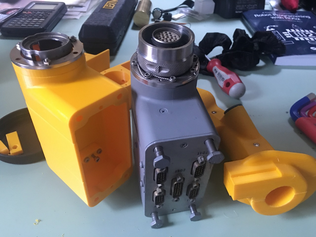
I have no intention of being compatible with anybody's interface, and be bound by their old rationale. I don't even intend to make money out of it... so no marketecture considerations of being compatible with anybody's stick or base either! For instance, if I put an RPi Pico in the stick body, I don't even need an electrical interface (ok.. maybe I will put in an SPI plug to read the Hall sensor and another plug for the force generation, just so you can unplug the stick and put in another stick shape). The stick has its own USB connector(s). But, remember that the stick has up to 30 buttons/switches, plus 2 axes. And I have provision for force generation. I would need at least 4x cascaded shift register chips if I went that way.... not exactly compatible with TM's interface either (not that incompatible... pin compatible, but not software compatible, just program it to do 32 instead of 24 bits). Anyway, even an RPi Pico does not have enough pins.... you might notice. What if I put two RPI Picos in there? Running as two separate USB controllers? DCS wouldn't mind. Says who there can be only one? The corporate bean counters might balk at the idea of two MCUs... I ain't got no bean counters. It was actually funny... When RPi Pico first came out... I was like... OMG... this is like custom designed as the new Hempstick! Except... damn... two pins short! Damn it! So close, yet so far! So, I spend a couple of days studying the MCU spec., the PCB design... trying to squeeze out two more GPIO pins. And one day... I had to slap my own forehead... doh... just stick two RPi Picos in there... done! Now that I came out of the stupid loop.... with n > 1 Picos... I am free to add more switches/buttons. Hey... each Pico board is only USD $4! Even one of my optical sensor costs about that much, let alone I have up to 30 of them in there! Negligible! I might use Pico W... $6. Maybe I will put there Picos in there. Two in the stick body taking care of all the buttons and switches... and one in the base to take care of just the Hall sensor and the force generation. You know, a bit more modular. No more wires going through the stick! Makes my life simpler! What TM PS2 connector interface? Ha! I count 21 pins in the real F16 stick connector.
-
Shift register is a good alternative to the matrix circuit, which I personally think is a better solution than matrix although others might disagree. But, remember, the shift register and matrix circuits are “solutions” to the problem that you don’t have enough GPIO pins on the MCU. Both are great solutions to the problem. But, why use them if you have enough GPIO pins? It would be wagging the dog! Why apply the solution when the problem does not exist? Ok… there is the number of wires to route. But, the real ones could do it, so could I. Challenge accepted! BTW, I have about 100 of those shift register chips in one of my part bins.
-
-
Well.... that's an idea!