Diesel_Thunder
-
Posts
544 -
Joined
-
Last visited
Content Type
Profiles
Forums
Events
Everything posted by Diesel_Thunder
-

Engine bearings and how you can keep them happy
Diesel_Thunder replied to Diesel_Thunder's topic in DCS: P-47 Thunderbolt
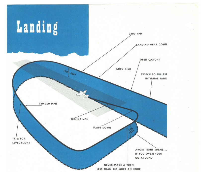
Here's the landing diagram from the real P-47N manual. It's the same as the D model pattern with two exceptions. The D model calls for 2,550 RPM and turns no less than 130 MPH, where the N model specifies 2,400 RPM and turns no less than 150. The sequence is as follows: Landing gear can be lowered below 200 MPH Flaps can be lowered under 190 MPH Reduce speed to 140-150 MPH Set RPM to 2,550, mixture to AUTO RICH, and propeller control to AUTO (electric switch on panel forward of the throttle lever) Turns in the pattern no less than 130 MPH Final approach speed 115 - 120 MPH Tail wheel locked The manual does caution against doing long, flat approaches as it leaves little time for emergency action in case the engine dies. It also advises against throttling up in turns as that pulls the nose up and steepens your turn. Absolutely! As airspeed decreases the prop governor brings the pitch back to maintain RPM until it hits the mechanical limits, and from that point RPM is controlled by power and airspeed. You know when this happens as the RPM gauge starts dropping from its setting of 2,550.
-
No worries. I know you and I are aware of that distinction in aircraft manuals, it was more for the benefit of others that don't know that.
-
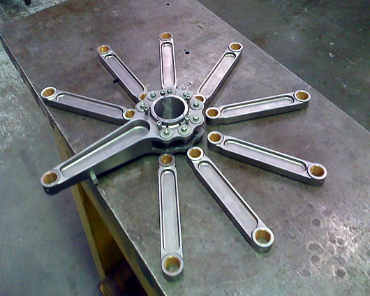
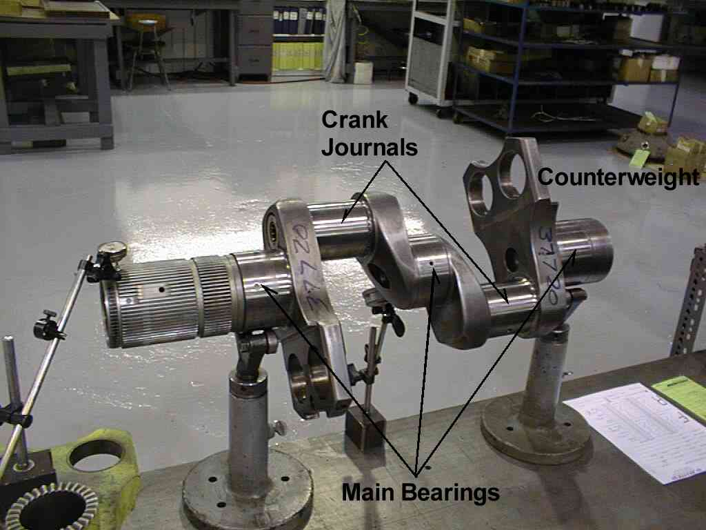
This seems to be a hot topic lately, so I've put in some research to learn as much as possible about this, and what we can do to mitigate the problem with wrecking our bearings. Background on the problem: This is a problem that is unique to radial engines, and is not much of a factor in inline or V engines, in that reciprocating loads can damage bearings. Under normal conditions, combustion happens, pushes the piston and connecting rod down in the cylinder, which turns the crankshaft. Crankshaft turns the reduction gears, gears turn the propeller, propeller creates thrust. This is true for both radial and inline/V engines. Lets briefly explore V engines, like the famous Merlin 61 V-12, used in warbirds such as the Spitfire and Mustang. The crankpins on the crankshaft were only attached to two connecting rods, and being a four stroke engine, only take the force of a power stroke only once per revolution. This is the key concept here, but bears repeating, the crankpins only take the force of a power stroke only once per revolution in a V engine. Here's a picture illustrating this. Note that two pistons share a crankpin. Radial engines are a whole different animal compared to their V shaped cousins. The crankshaft layout is a lot simpler, with one row of cylinders sharing one crankpin. The cylinders are then spaced evenly around that point, and nearly always feature an odd number of cylinders in that row. Having an odd number of cylinders simplifies the ignition timing, as every other cylinder fires in turn. (a nine cylinder would have the firing order of 1-3-5-7-9-2-4-6-8) Since all of the cylinders have to share one crankpin, the crankshaft is built much larger and stronger to handle the forces involved. The connecting rods also have a unique arrangement, with one serving as the master rod which connects to the crankshaft, and the other cylinders rods are articulating rods that bolt to the master rod. Looks something like this: On to our R-2800 engines now. The cylinders in one row, nine of them spaced 40° apart, share one crankpin, and every other cylinder fires as the engine runs. The crankshaft thus takes the force of a power stroke every 80° of rotation, or 4.5 times every revolution in each row. Contrast that with the V engine where a crankpin only takes one power stroke every revolution. That's a lot of force on the crankshaft, but fortunately Pratt and Whitney thought this through and added a hole for pressurized oil to flow in between the crankshaft and master rod assembly at the correct place where a power stroke would be pushing down on the crank (the thrust side). You certainly don't want any metal on metal contact, especially in the one spot on the crankshaft where power strokes are pounding down on it. A lot of radial engine crankshafts featured this oil hole, not just ones built by P&W. Here's what the R-2800 crankshaft looks like. There are several bearings pointed out here, the mains and the crank journals. The mains are supported by the crankcase, and are not the ones that we damage by running the engine improperly. Those would be the crank journals that take the damage. There are only two, one for the front row, and one for the rear. In the photo, if you look at the rear crank journal (right hand side) you can see the oil hole for that bearing facing downward. This (and a lot of others) radial engine were very well designed, and provided many hours of reliable service (combat damage and ham fisted pilots not withstanding). So how do the bearings get damaged? By reversing the reciprocating load on them, or in other words, windmilling the prop. The engine is designed to provide power to the prop and is built to do exactly that. When power is reduced and sufficient wind speed exerts more force on the prop than what the engine is providing, the loads in the engine are reversed by 180º. The prop is now driving the crankshaft, which is now moving the pistons around. The crank journal is taking the load on the side opposite of the oil hole, where there is very little oil. This leads to metal on metal contact, an overheated bearing, and metal in the oil, loss of power, and given enough time, total engine failure. This is likely amplified somewhat in that since the engine is still turning it has oil pressure, and that is likely exerting some hydraulic force on the thrust side of the crank, pulling the opposite side in a bit closer. Oil pressure eventually falls and the oil temperature rises due the engine wear and friction (not sure if DCS models this behavior). While this is happening the piston rings are also fluttering in their grooves, leading to damaged ring lands and broken rings (not sure if DCS models this either). How quickly damage accumulates is a function of severity and time. A high RPM steep dive would damage the engine more rapidly than a moderate RPM shallow dive. Now that we know the how and the why the bearings get damaged, how do we prevent it, and why does this happen more during landings? And with that, how do we know when the engine is being windmilled? The point where the engine starts to be windmilled is different between aircraft (weight, speed, props, RPM, and MP settings). Aircraft that had a BMEP gauge or torquemeter had a decent idea of when this happened as those instruments were a good direct measurement of power output. Other aircraft just had to make do with the RPM and MP settings. One of the old "rules of thumb" was to keep at least one inch of MP for every 100 RPM. If you're doing steep dives link the prop lever with the throttle and pull them both back during the dive. Don't close the throttle entirely during the dive, keep some power on. For landing techniques, there are two schools of thought. The military method and the airline method. I'll elaborate on both, but keep in mind the time frame of this (1930's to 1960's), the heyday of radial engine aircraft. The military technique mostly utilized the overhead break landing pattern, with a high RPM setting during the approach. The Mustang usually had 2,700 RPM set, the Jug set 2,550 RPM. The Air Corps/Air Force preferred to have its pilots ready for a go around, hence the high RPM setting. During the war, if the engine could be used for the next mission, great. If not, a new one was installed and the damaged one sent out for overhaul. This mentality carried on into the Cold War when the military had a fairly generous budget. Keep in mind that jets were up and coming as well. Accident rates with them were higher, mostly due to pilots transitioning from piston engines to jets. Piston engine can deliver power pretty quick when you push that throttle up, early jets not so much. Jet engine spool up times took a lot longer than pistons, especially if one was on short final. It took a while for the Air Force to adopt the stabilized approach (high drag, high thrust) with jets. The high RPM approach with pistons, stayed with them. Better to risk engine damage and a go around in order to use the plane (and pilot) again. Maintenance costs were not of much concern. If you are going to use the military high RPM approach, follow the 1" MP per 100 RPM rule of thumb. With RPM set at 2,550 RPM, don't let the MP fall below 25", until you are on final and near the flare. By then your airspeed should be between 90-110 MPH, and your RPM should naturally fallen some. The prop should be sitting on the low pitch stops and there won't be sufficient wind speed to drive the prop. The airline technique was much different. They had to stay profitable and keep happy customers, and work within much tighter budgets than the military. Pilots wrecking engines would eat up maintenance budgets with replacement engines, not to mention taking a bird out of service and cancelling flights. Aircraft only make money when they are flying. Their technique with descents and landings was to start down sooner (shallower descent) while keeping the engines at cruise RPM settings (around 1,900 RPM). and also not allowing the MP to fall below the 1" per 100 RPM (or following specified BMEP or torque setting if equipped with that instrument). This would be maintained during landing, with the the RPM brought up at the flare when the throttles are closed when there was no risk of the prop driving the engine. This led to quieter operations and higher engine longevity. This method gives some more flexibility with power settings as you are not constrained to a fixed RPM during the descent and approach. The key points in summary: Radial engines are pretty tough, but can be easily damaged if its pilot is not careful with the engine settings. Pull the RPM back before entering a steep dive and keep a little bit of power on. During descent and approach, keep at least 1" of MP for every 100 RPM to ensure the engine is providing power and not being driven by the prop.
- 24 replies
-
- 19
-

-

-
You're welcome! I saw that, but it is only a recommendation and not a limitation or restriction. The last few pages in the manual contradict that by giving cruise settings below 2,070.
-
The F-16 had similar pitot icing issues for a while as well, except for the part about draining the batteries. I think that did get resolved, though it took a while.
-
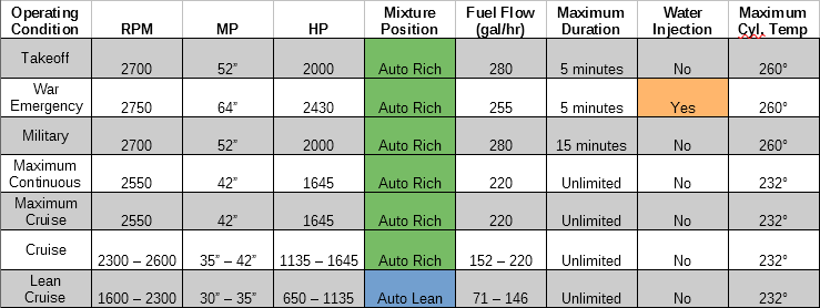
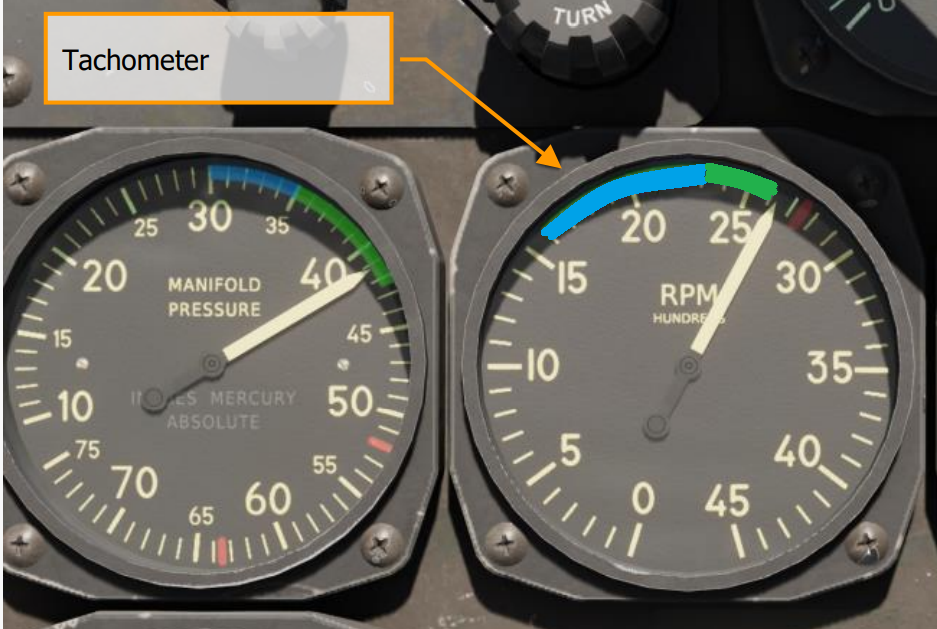
While reading through the DCS manual for the Jug, I noticed that there was not an engine limits chart like the Mustang's manual has (pg 32). So I creating one using data from the DCS P-47 manual, real life P-47 25-35 manual (thanks for posting that grafspee), and published data for the R-2800 engine. Like to think this would be a handy reference for my fellow Jug pilots. Some thing to mention about lean cruise. The real manuals have tables with power settings (MP and RPM), altitude, and aircraft weight for specific range and fuel flow at cruise power (both auto rich and auto lean). Auto lean has substantial fuel savings in gallon per hour as you'll see on the chart. The blue arcs on both the MP and RPM gauges are a quick reference for the pilot for when you can operate in auto lean, with the specific power settings listed on the tables in the manual as mentioned. Both needles have to be within the blue arcs in order to use auto lean. CAUTION - The tachometer in our DCS P-47 has backwards colors for the green and blue arcs. The arcs are the proper span based on published data, but the colors are reversed. Below is a corrected screenshot of the proper color arcs. *** NOTE: The blue and green tachometer arcs have been corrected. Unsure when it was corrected as it was not documented in any patch notes, but it was fixed at least as of Open Beta 2.7.10.19473. *** WARNING - Do not dogfight in auto lean! If you are in lean cruise, be sure and shift back to auto rich before bringing up the power for aerial combat. You risk overheating the engine and damaging it (very high risk of detonation). Later models during the war had different carbs fitted where there were only three mixture settings (cutoff, auto, emergency rich) like in the DCS Mustang. It was one less thing for a pilot to forget if he got bounced by enemy fighters, and the carb would set the mixture lean or rich as needed based on power settings. Corrected tachometer arc colors: - 14MAR22 - Noted changed regarding tachometer color arcs.
-
That's a good sequence, except for the part I highlighted in red. During warmup, we are not to ever exceed 1,000 RPM until the oil temperature is at least 40°C and the oil pressure is no higher than 95 PSI. Running up to 1,500 RPM on a cold engine is a sure way to damage it. Thankfully with the Jug being air cooled, it does not take too long for things to come up to temperature (unlike the liquid cooled Mustang). Also better to set the parking brakes prior to engine crank. To help keep from running down the battery, one could (and should) call for ground power. Just make sure the battery switch is in the OFF position while on ground power. We can taxi on a cold engine without exceeding 1,000 RPM, since the Jug will start rolling between 800-900 RPM. This not only gets you to the runway sooner, but also warms up the engine the same as if you were stationary on the ramp.
-
reported Rev indicator,color green and blu
Diesel_Thunder replied to oreste's topic in Bugs and Problems
After putting in some good time and research on this, I do believe the P-47's tachometer colors are indeed reversed. The span of the arcs are correct, and at the correct RPM ranges, just the colors are reversed. The excerpt that @oreste posted above from the real P-51 D/K manual, the real manual that @grafspee posted in another thread that covers the P-47 25 - 35 models, and the real manual that I found for the P-47 N all agree with this assessment. The blue arcs were painted on both the MP gauge and tachometer for the pilot as a quick reference for setting the mixture to AUTO LEAN for long range missions. Both gauge needles had to be in the blue arc in order to use auto lean. There are quite a few tables published in the manuals with RPM, MP, fuel flow, mixture setting, and true air speeds that can confirm this. I've attached a screenshot of of what it should look like:
-
reported Rev indicator,color green and blu
Diesel_Thunder replied to oreste's topic in Bugs and Problems
The colors are not flipped on the RPM gauge, that is the intended colors. Increasing the RPM has the effect of reducing the cylinder combustion pressures, which in turn reduces engine stress and cylinder temperatures. Especially at lean cruise settings, which was desirable for long range missions. Decreasing RPM at the same settings raises the cylinder pressures and more importantly the temperature. This reduces your detonation margins, making it a lot easier to damage the engine if the pilot wasn't careful with his power settings. I recall reading some figures that the difference in fuel consumption at cruise power was around 20 gallons per hour between the rich and lean setting on most single engine R-2800 powered aircraft. Lot of science and engineering goes into these amazing engines. EDIT: I was incorrect with this post, see below. -
P-47 Engine Failure during landing approach.
Diesel_Thunder replied to Lykurgus's topic in DCS: P-47 Thunderbolt
You may be windmilling the engine, which puts the load on the wrong side of the crankshaft and can wreck the bearings and engine depending on how badly the engine was being windmilled. The loaded side of the crankshaft journals feature a lubrication hole that protects the crank from the forces of the power stroke from each cylinder, since each power stroke applies force to the same spot on the crankshaft. When being windmilled, the forces are reversed, applying force to the opposite side of the crankshaft without the lubrication hole. Try keeping a little more power on, so that the engine is driving the prop during your approach. -
Underboost is not too terrible in itself, but can easily lead to the engine being driven by the prop, which is horrible for the main bearings. Here’s why: With radials, each row of cylinders only has one crankpin. In the R-2800, this means 9 cylinders share one crankpin. One cylinder in the row will have a master connecting rod that connects the piston to the crankshaft, the other 8 in that row will have articulating rods that bolt to the master rod. The key thing here is that all cylinders in a row share the same crank pin. This is unlike most engines in use today in cars and trucks, where each cylinder has it’s own crankpin. In the case of V engines, the crankpins are typically shared by 2 cylinders. The forces on the crankshaft are reduced because of this, as the bearing surfaces only have to handle one power stroke per revolution. Back to the radial. Because all rows share one crank pin, that surface has to take the force of 4 or 5 power strokes in each revolution. Nearly all radials have rows with odd numbers of cylinders, 9 per row in the case of our R-2800. This is to help simplify the firing order of the cylinders in each row, which is every other cylinder (1, 3, 5, 7, 9, 2, 4, 6, 8 ). The cylinders are set 40° apart (360/9=40). Every 80° of crankshaft rotation, there is a power stroke in each row of cylinders, and that power stroke pushes on the same spot on the crankshaft. That crankpin takes a lot of force in that one area each time a cylinder fires, and is heavily built for that reason. One other thing that the engine builders did to help those bearings and crankpins stand up to these forces was to drill a hole into the crankshaft that would supply pressurized oil right between the crank pin and master rod at that spot where the power stroke would push to keep the two well lubricated, and more importantly, keep the two from ever touching (metal on metal) and keeping the engine and pilot airborne and happy. Now, if the engine is at a low power setting, and with decent airpeed, the prop now becomes a windmill and starts driving the engine. Here’s where the problems start. The forces on the crankshaft are now reversed. The crankshaft is pushing the pistons around, and with that the oil hole is on the wrong side of the bearing in this instance. The lubrication on this side of the crankshaft is considerably less, and with the prop driving the engine, usually isn’t enough to prevent metal on metal contact. This is what will wreck the bearings (combat damage not withstanding). How long an engine can tolerate that is a matter of how hard it is being driven by the prop. High RPM and low power in a steep dive would be more harmful than low RPM and low power in a shallow dive. The key takeaway is not allow the prop to drive the engine as best possible, and to minimize the potential for that to happen. Keeping some power on in a dive would keep the crank shaft loaded properly and mitigate the problem entirely. Here’s a great link where one could learn more about this with math, diagrams, and an author with loads of experience: https://www.avweb.com/features/pelicans-perch-78-props-driving-engines/
-
[ALREADY REPORTED]External lights inverted?
Diesel_Thunder replied to ebabil's topic in Bugs and Problems
I can confirm this. This happens to the lights whenever there are no external hardpoints installed. And it does not matter what skin is selected. No hardpoints - the DIM / BRIGHT switch behavior is backwards Hardpoints installed - the DIM / BRIGHT switch behavior is normal Here are two tracks to confirm this, one with hardpoints, and one without. huey no hardpoints.trk huey with hardpoints.trk -
Negative G for long enough would snuff out both engines. IIRC 10 seconds at max power is the limit before the collector tanks at the engines go dry.
-
Required stick input at rotation
Diesel_Thunder replied to Meyomyx's topic in DCS: A-10C II Tank Killer
Also to add, be careful pulling too much, as you can end up striking the tail against the runway. -
It’s been happening for quite some time. I noticed this back in March and posted about it before. Would be nice to get this fixed. For me it’s an annoyance when doing touch and go’s or a refuel/rearm that I can’t follow radio procedure. https://forums.eagle.ru/forum/english/digital-combat-simulator/dcs-world-2-5/bugs-and-problems-ai/general-questions-ac/276482-atc-comm-issue
-
Are you referring to the pull handles, or the discharge selector switch? IIRC the pull handle cuts off fuel to that engine, and also designates where the extinguishing agent will go. The L/R discharge switch does not select an engine, only selects which extinguisher bottle you want to discharge.
-
I did this a few months ago when my main PC drive got too full, and I was unable to install all my purchased modules. I bought a Crucial MX-250 SSD, and just used Windows to transfer the file folders from one drive to the next. After that I just updated my desktop shortcuts with the new drive letter. I did not have to change any registry settings and DCS has been running happily since. Good luck!
-
From what I understand, the audible warning is supposed to just be for the landing gear and nothing else. In the A-10C I Warthog we had, it sounded for everything, which was incorrect. ED corrected it for both the Warthog and Tank Killer when it released last month.
-
That's the way China Hat aft is supposed to work, and not TGP boresight. There is supposed to be a B-S button on one of the OSB's on whichever MFD has the TGP, which does bring the TGP back to boresight. I think we'll get it in the next beta update.
-
The MAIN and WING tank pumps are AC powered, which means you need to have the APU running and online, or the main engines running and generators switched on. Only then will the AC pumps get power and start pumping fuel. There is a small automatic DC powered pump, that the battery will run. But it is a small pump, and only meant to provide fuel to the APU so it can start.
-
Ah, I see where you were going with that now. Sorry for misunderstanding that. And yes, with the wastegate open, you would hear a lot more noise from the wastegate stack pipe than you would if it were closed.
-
If the turbo is bypassed (full open waste gate), then the engine will operate as any other supercharged radial with power output determined by RPM and throttle setting. Darn near every piston engines power output is determined by RPM and fuel rate. All the turbo did was to help put more air into the cylinders to allow more fuel to be burned and make more power. The waste gate itself doesn't control power, not directly anyway. Mostly meant to keep the turbo from an overspeed condition (bad for the turbo), or overboosting the engine (bad for the engine).
-
It doesn't, and it's not supposed to. From what I've read here previously, that compass in the video is low on dampening fluid which is why you see it react from the gun fire vibration. Normally they are full or nearly full.
-
I may be wrong, but I thought the radar altimeter is inhibited with weight on wheels. In other words, it only transmits when the aircraft is off the ground.
-
The Hog cannot do more than 10 seconds inverted at max power before the collector tanks at the engines go dry and the engines flame out. Those tanks are there to keep the engines going during brief periods of negative G flight, but not sustained negative G's.