
kablamoman
-
Posts
427 -
Joined
-
Last visited
-
Days Won
1
Content Type
Profiles
Forums
Events
Everything posted by kablamoman
-

Gauges related to Pilot tube freeze at high altitude.
kablamoman replied to Rainbowgirl's topic in Bugs and Problems
I think a major polishing pass needs to be done for almost all instrumentation. Off the top of my head I can think of long-standing bugs with the gyro instruments, the pitot-static instruments, and the magnetic compasses with pretty much every single warbird module. Bonus points if they can add cool little visual treats like bouncing tach needles and such where appropriate (I think the mosquito may already do this, but I don’t have that one). -
Please Update the Kneeboard Functionality (Especially for WWII)
kablamoman replied to TPrince's topic in DCS: The Channel
Hard disagree. It is every bit as accurate as a GPS in that you get your exact position any time you want it. In real life when using visual references and charts it can be shockingly easy to mistake similar towns, lakes, rivers, roads, or combinations of them for completely different locations on your map, leading to gross navigation errors. The other scenario is of course cloud or visibility challenges, as you mentioned. The way the kneeboard works currently, allowing you to place an exact mark on map with your precise position is not at all similar to how you navigate in real life, and completely invalidates the skill set one must learn to navigate IRL successfully. Quite a stretch to call it gatekeeping, and the mark functionality should be a prime candidate for a server side enforceable “realism” or “difficultly” setting. -
Please Update the Kneeboard Functionality (Especially for WWII)
kablamoman replied to TPrince's topic in DCS: The Channel
I don’t know about that. The way it works currently means that it’s effectively a GPS with a moving map, except a bit more cumbersome to range in and out, and with the map in low resolution. I’m all for making improvements that allow it to be used like it would be in real life (ie. actually using it to navigate). -
That love also broke 3 separate instruments, though. Don't get me wrong, I think everybody appreciates any kind of WW2 update (we're all starved for them, as you mentioned, and would love to see more), but things like this hurt precisely because updates are already so few and far between.
-
Don't forget the glareshield geometry is incorrect in the Anton. Makes the thing look wrong. Glad they've reported it already -- hopefully they're able to fix it sometime soon.
-
FW-190: Anton or Dora? DCS Sale
kablamoman replied to bruzogiri's topic in Controller Questions and Bugs
Counterpoint to the rear airfield spawns: It takes you a while to climb to an advantageous altitude anyway (the Dora really shines, even without the MW50, between 6000-8000 meters). I think flying style could be considered when picking one of the three modules. There is no question that the 109 is a better in general at actual dogfighting -- it has better turning ability than both of the FWs and centerline weapons that pack a punch. But If we're talking about survivability, as is often the case on 4YA, I'd say the Dora may be best suited for air-to-air engagements in this regard, as you can usually run and keep your distance if you don't stick your neck out too much. The Anton, while underpowered with regards to its engine, is no slouch with its armament and its considerable firepower can often make up for less-than-stellar arial gunnery, and is the best suited of the three for ground attack. I say trial them all and see which one suits you best! -
investigating Cannot calibrate Gyro with Mag Compass
kablamoman replied to Nealius's topic in Bugs and Problems
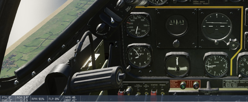
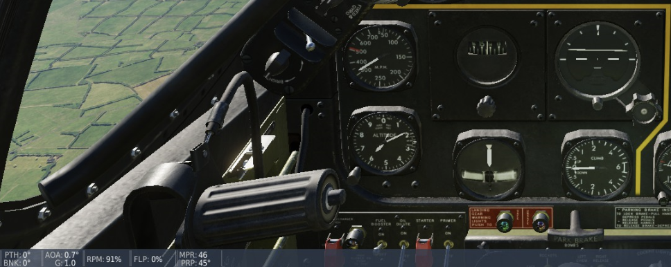
Yes, still an issue. The magnetic compass is susceptible to excessive “tilt” error any time the deck angle of the aircraft is not level with the horizon. In the Bazenville example near the top of the thread, when aligned with runway 6, instead of reading 65° magnetic, heading on the compass can be out as much as 25 degrees (90° magnetic) with a slight pitch up attitude. The compass incorporates a pivot and float device that should rotate freely when tilted and should not be so drastically affected by inclination/dip errors (see the remote sensing unit test tolerances for tilt error I posted here). -
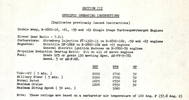
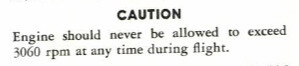
Seems there may be a bit of confusion. The 2880 and 2980 limits you posted vs. the 3060 limit are simply due to them being figures for different engine models. Max diving speed (30 seconds): R-2800 S1A4-G: 2880 RPM R-2800 2SB-G: 2980 RPM R-2800-59: 3060 RPM The first two engines seem to be export variants (an A series and B series engine, respectively), while the -59 is the B series engine used in our DCS P-47. The figure has nothing to do with the prop. The notes in the procedure about “some cruising value” are suggesting a lower RPM and manifold for entry (unless MIL is being used tactically, ie. fighting) to give the governor more of a head start on blade angles. Indeed, the 47 manual recommends a 2600 RPM entry. Once the blades are at their coarse limit, however, as they will be eventually in a high-speed dive, it does not matter what the pilot has selected for their RPM — the blades will have reached their coarse limit and the engine will start to overspeed with increased airspeed. Where the material you shared is really helpful is seeing that it recommends at least 12 - 15 inches of manifold (and even higher if able, according to the chart) even if the engine is already overspeeding! It’s saying that to help prevent reverse loading on the master rod bearings you should keep as much manifold applied as practicable, likely overspeeding the engine even further, up to the 3060 RPM value (not to exceed 30 seconds). This procedure is absolutely impossible with the current engine modelling, and highlights a deficiency many have noticed in the sim. Increasing the allowable high angle of the blades to 53° as per the technical order posted would likely bypass the issue entirely. However, if they choose to retain the current 48° angle governing limit, these overspeed failure modes should probably be properly addressed. In either scenario, I do not believe the separate “feather limit” of 88° (or anything beyond the auto-governing limit) one can manually achieve by using the manual decrease RPM switch is accurate, and it should probably be fixed.
-
cannot reproduce Engine issues when using MW-50(bug?)
kablamoman replied to oncomms's topic in Bugs and Problems
I can only say that the only emergency power associated with the notzug handle was the “sonderstartspitze” introduced with the Juno 213A G-1 designation for a couple months at the end of ‘44. It was for take off up to 500 meters. But because we also clearly have the 1.5/2700 RPM limitation specified in our manual when using the notzug handle, it would seem that our engine is from after this designation was rescinded and so should not be used. As saburo mentioned, the 3 minute limit seems to be another conflation regarding “Erhöte Notleistug” that wasn’t installed (we have no switch for it in our aircraft) in aircraft equipped with MW50. -
cannot reproduce Engine issues when using MW-50(bug?)
kablamoman replied to oncomms's topic in Bugs and Problems
The 3 minute limit is an instance of the DCS manual being a bit confused by what was a briefly approved (and subsequently rescinded) operating regime. More details in this post: -
Here are the equivalent -59 numbers:

-
I don't have the mosquito, but the same problem certainly seems to be pervasive throughout the sim in all of ED's modeling of traditional (steam gauge) artificial horizons. Here's a post I made with regards to the one in the mustang that I think outlines the issue fairly clearly: Hopefully ED is able to revisit how they've modelled these instruments.
-
@jackd I don't think the update has been finalized yet. This is an announcement of improvements to come. Great to see additional updates! Good job, guys!
-
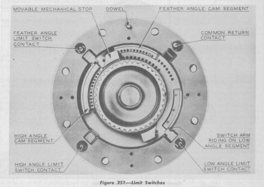
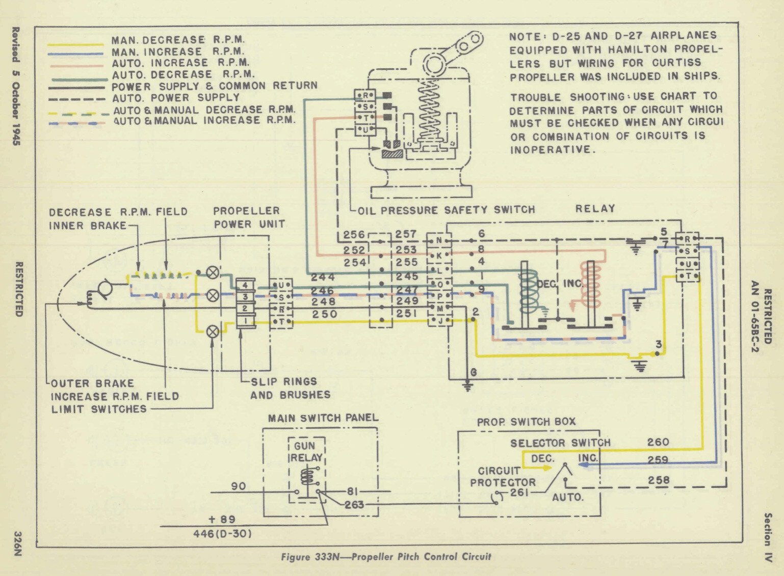
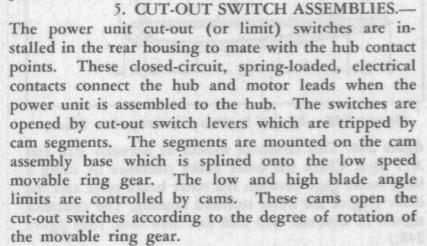
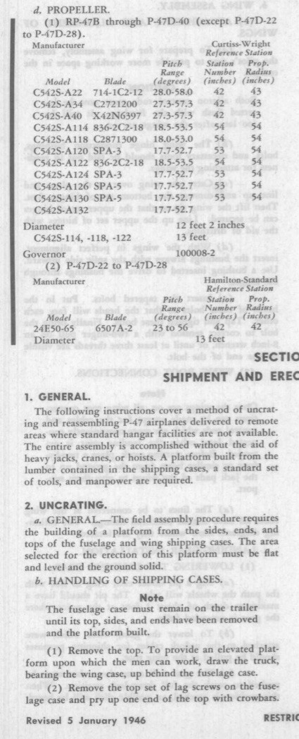
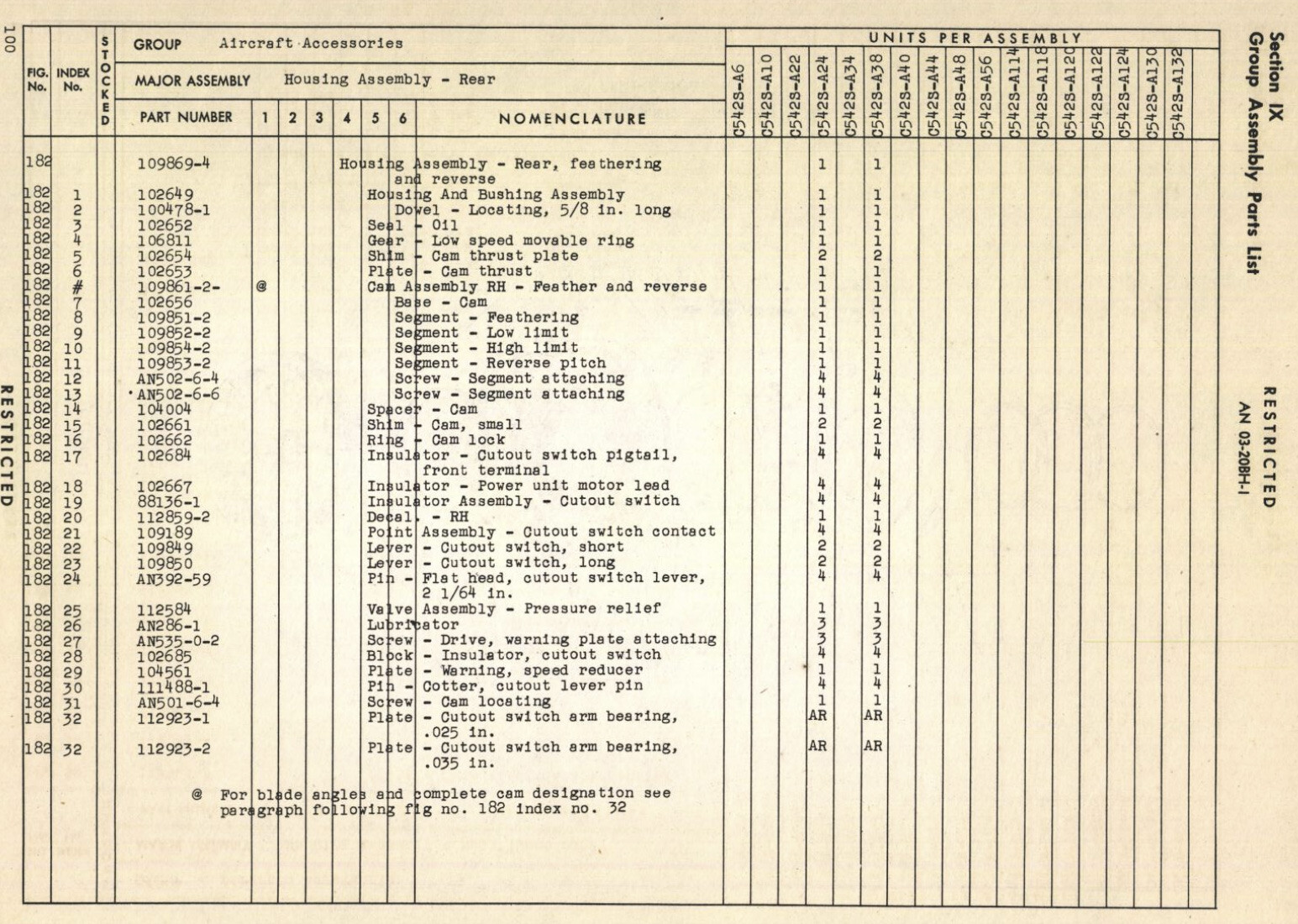
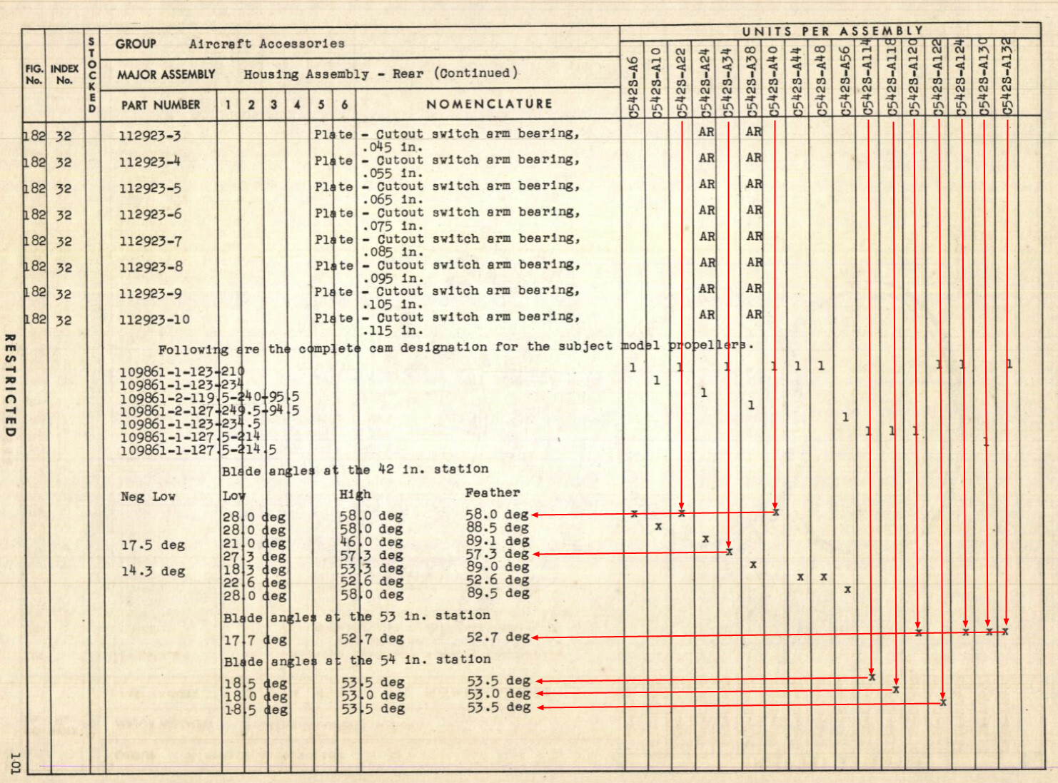
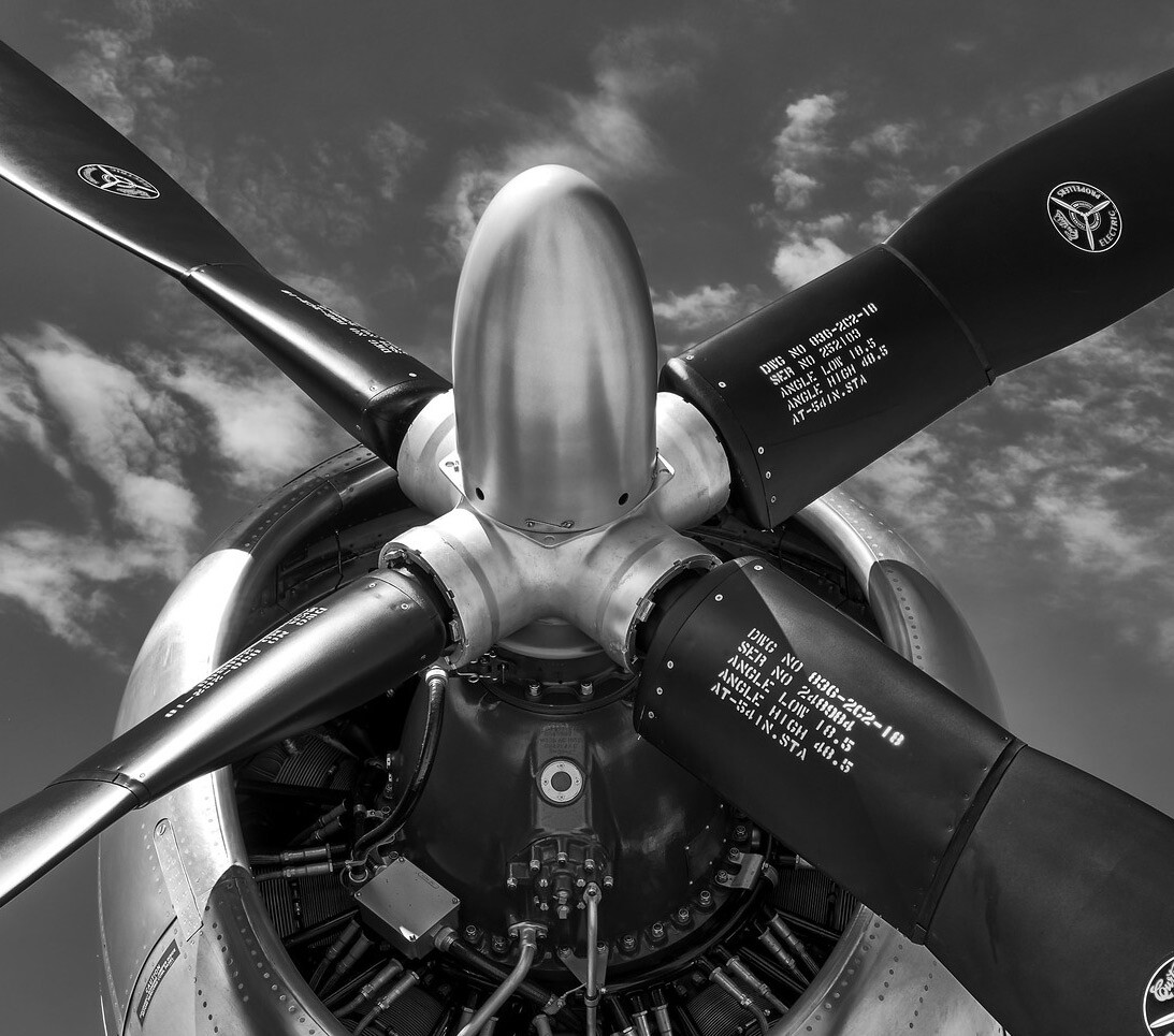
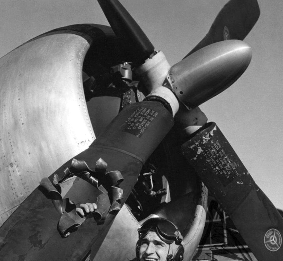
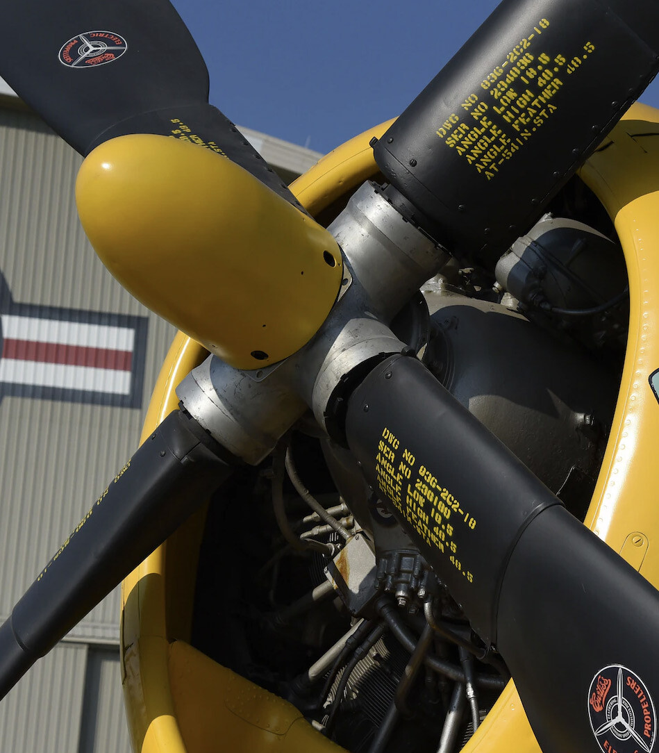
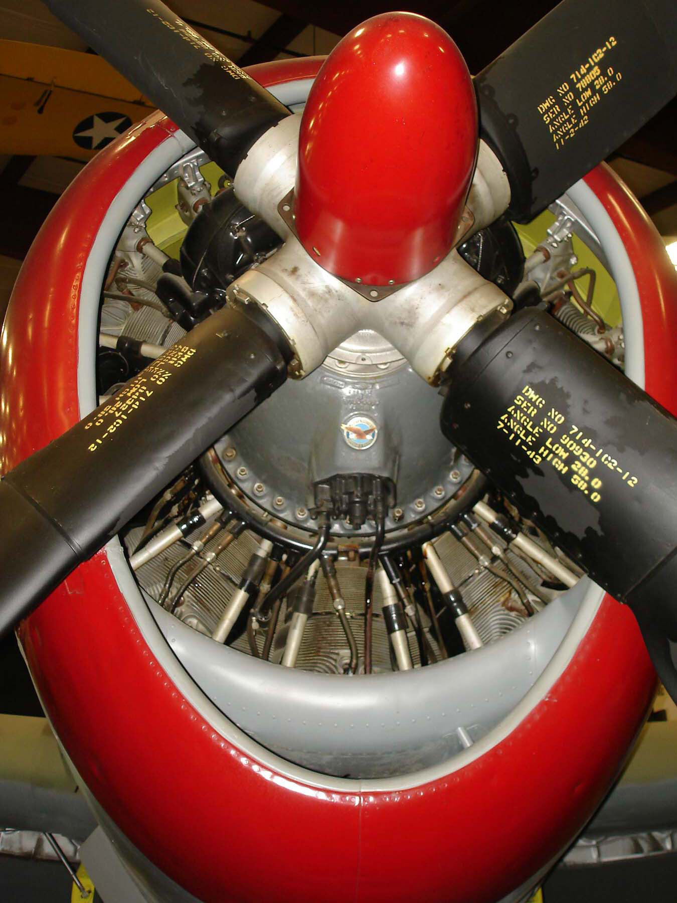
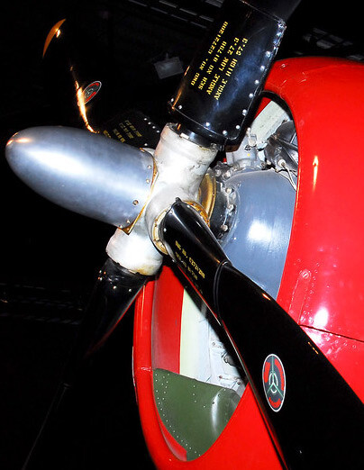
I wanted to do a bit of research with regards to the Curtiss Electric prop as modelled in the DCS P-47 modules in order to ascertain what is going on with the blade angle limits, and whether or not the behavior of the automatic governing vs. manual RPM adjustment was correct as we see it in the sim. As modelled currently, the governing range of the blades in the automatic mode reach their limit at 48 degrees coarse. Yet, by going into manual mode, you can further coarsen the blades to ~88 degrees -- what would be considered feathered. But this does not make sense for a single engine installation. I suspected that maybe the devs had erroneously modelled propeller limits for a multi-engine installation of the Curtiss electric prop and set out to understand how the limit switches (analogous to mechanical high and low pitch stops in a hydraulically actuated prop) function and how they should be configured in a P-47. For this I started out referencing the P-47 series Erection and Maintenance Instructions handbook (AN 01-65BC-2) 10 August 1944, revised 15 December 1947: As you can see, the depiction of the limit switches (mounted on the aft portion of the power unit, which also contains the electric motor) specifies three limit switches: Low angle, high angle, and feather angle. It is important to understand that all Curtiss electric prop installations have these switches as the props can be fitted to many types of aircraft. Indeed, some installations would be for multi-engine aircraft (eg. the B-26), where a separate feather limit would be needed. If one were to look at the wiring diagram for the control mechanism, and also if you read the user manuals for the Curtiss electric props, you can see and read that while the manual increase RPM switch uses the same circuit as the automatic governor, the manual decrease RPM switch makes use of a separate control circuit, one that doesn't pass through the high limit switch, but instead the feather limit switch (follow the yellow line): Indeed, in the generic Curtiss prop user manuals, it mentions that pilots can manually decrease the angle all the way to feather limits (albeit, at a slower rate than using the dedicated feather control on a multi-engine installation) if they use the manual RPM decrease control. One must remember that these manuals (you can check one out here for yourself) are made to encompass general usage of Curtiss props across several types of installations, and so are a bit ambiguous in specifying whether this feature works for a single-engine installation. If this was all there was to the story, the DCS modelling is correct as is. However, we also have this description of the limit mechanism: It mentions that the switches are tripped by cam segments mounted onto the ring gear. It turns out that how those cam segments are mounted, determines when exactly the switches will be tripped. How should they be mounted in our P-47? Which Curtiss electric prop models are installed on our P-47s? Here's what the Erection and Maintenance Handbook says: As you can see, we're already getting some hints about prop pitch ranges, but seeing as how we've got specific models listed and they all seem to be variations of the C542S-A series, let's take a look at that manual: There's a ton of information in here about installation, disassembly and description of components, but we're interested specifically in those cams: Here's the diagram, parts labeled 7-11 are the cams that determine when exactly our limit switches will trip. Notice at the bottom, we've got a note about blade angles?? Hey, we may be getting pretty close here. Let's have a look: Here, I've cross referenced all the specific model numbers listed in the P-47 Erection and Maintenance handbook, and you can see that for each of them, the High and Feather limits are exactly the same -- this means that a manual decrease of RPM should result in the same blade pitch governing range as the automatic mode. But why is our high/feather limit different than what we're seeing in game? To shed some light on this, here's a technical order from June of 1945: As you can see, at a certain point, blade angles were increased (the procedure involves moving those cams by 5 notches towards a higher coarse limit). There is still a discrepancy between this technical order and the curtiss prop manual, but I am assuming that is because the curtiss manual is 5 years more recent (1950). The one thing this does seem to prove, though, is that in all instances the curtiss electric prop installation on the P-47 had the same coarse pitch limits, whether governing in automatic mode, or set manually with the decrease RPM switch in fixed pitch mode. Also worth noting is that the increase limits in the technical order were done to help prevent engine overspeed in high-speed dives. Lastly, would like to reiterate the fact that, as others have mentioned multiple times on this forum, that the allowable engine overspeed limit in the P-47 pilot manuals is listed as 3060 RPM, probably owing to the fact that you WILL exceed the RPM redline in a dive at high speeds with any power applied: I believe getting the proper blade angle limits implemented would be a great first step on the road to really tightening up the P-47 module. Thanks for following along and I hope the devs really consider taking a second look at this.
-
I haven't had a chance to try it out myself, but looking at your video -- oh man. It looks like they messed it up even more than it was before. Previously the lubber line moved with the bezel when it shouldn't have. Now it's stationary but it looks like the bracket that you're supposed to use to line up the bezel with the airplane doesn't move either now, when it should. So now it's even more broken! One wonders who is testing this stuff!
-
Automatic manifold pressure regulator question.
kablamoman replied to grafspee's topic in DCS: P-51D Mustang
I am guessing you mean how when climbing at say, max continuous (46”/2700 RPM) there is a point where the manifold pressure starts to drop and you need to push the throttle forward to compensate? I am wondering if maybe it’s just reaching critical altitude a little earlier as the engine RPM isn’t max and so is not driving the supercharger as fast? Perhaps the regulator is calibrated with a certain RPM in mind? I honestly can’t remember if it behaves the same way at 3000 RPM. Maybe worth a test to see? I would like to understand how it works a bit better myself. -
artificial horizon-always tilts to a side after start up
kablamoman replied to 9.JG27 DavidRed's topic in DCS: P-51D Mustang
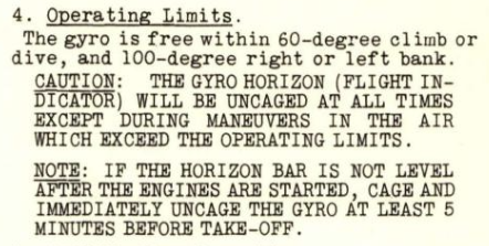
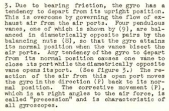
I don't have the mosquito so I can't vouch for how they've modelled it, but basically there is a constant, self-correcting mechanism in this instrument that seeks to align itself with the horizon based in the acceleration force of gravity acting on the pendulous vanes. If the instrument is uncaged in an unusual attitude, or an attitude slightly off of perfect alignment with the horizon, it should quickly correct itself within the specified timeframe (probably even quicker than the max tolerance allowable). Currently, the tendency to self-correct is either not modelled at all or is so slow that the instrument would be considered unserviceable. -
artificial horizon-always tilts to a side after start up
kablamoman replied to 9.JG27 DavidRed's topic in DCS: P-51D Mustang
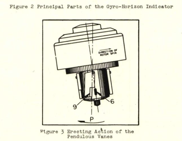
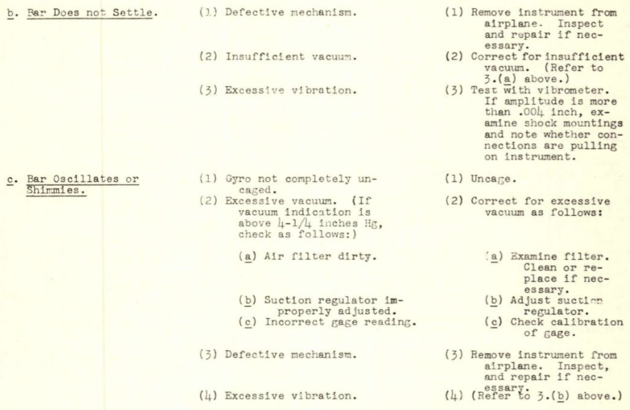
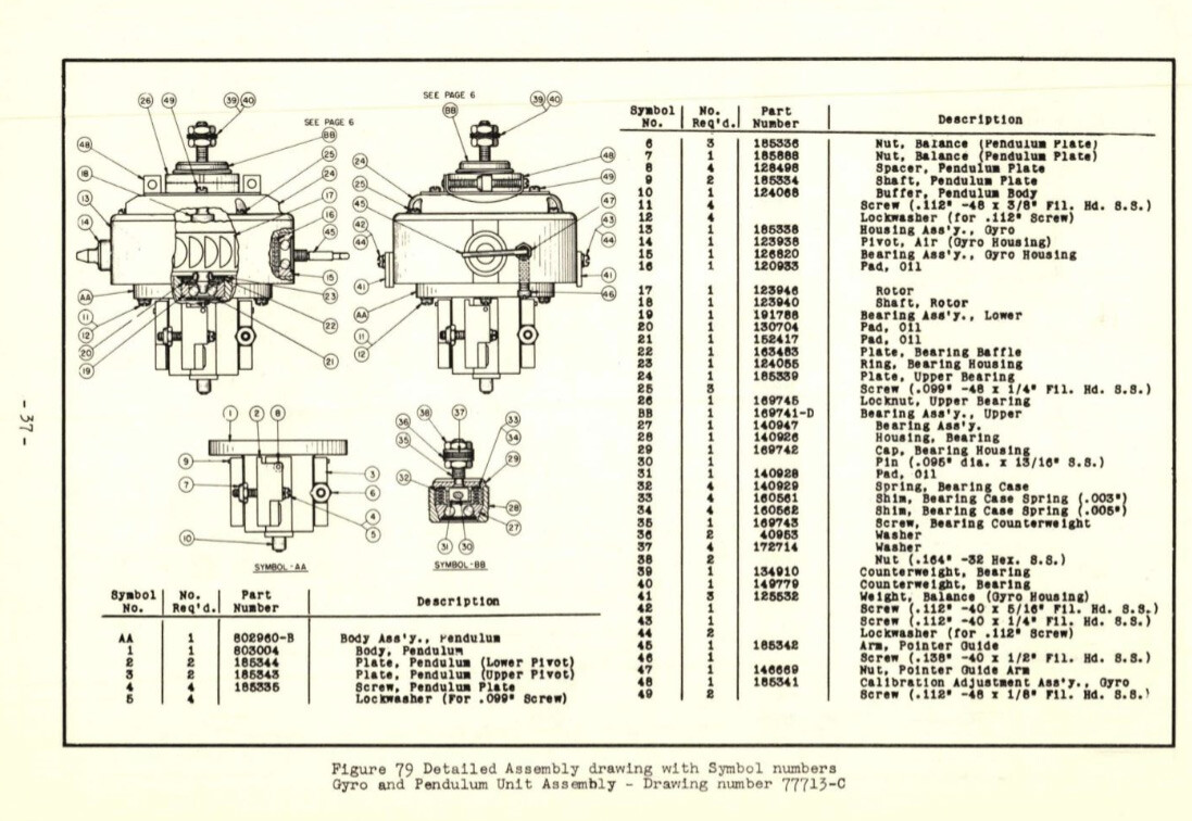
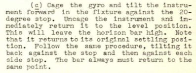
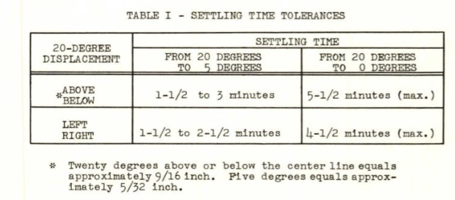
Here's the diagram depicting self-erecting mechanism of the P-51's gyro horizon (from the operation and service manual): Some notes on operating limits. Note procedure for uncaging on the ground before takeoff: From the troubleshooting section related to the "Horizon Bar" not settling: Here's a diagram of the pendulum assembly: A blurb from a section about proper calibration of the self-erecting mechanism: Table showing the time tolerances for the horizon bar to settle (self-erect): One can perform a pretty simple experiment with our in-game P-51. Cage the gyro, pitch up to 20 degrees (use the info bar), uncage the gyro and return to 0 degrees pitch with the info bar. The gyro will read 20 degrees nose low. Can you guess what the gyro ends up showing after 6 minutes at max continuous (plenty of engine power to drive the vacuum pump)? 0 minutes: After 6 minutes: At most, it looks like the gyro may have corrected itself by 2 degrees or so. Certainly not the full 20 degrees, back to the level horizon it should be capable of, and by any metric I can find in the maintenance manual for the instrument, it would be considered defective.
-
artificial horizon-always tilts to a side after start up
kablamoman replied to 9.JG27 DavidRed's topic in DCS: P-51D Mustang
I think this is just muddying the waters. Modern restorations use updated instruments and avionics for a variety of reasons, but many still do incorporate original flying instruments. The crux of the issue is that the instrument simply isn't modelled correctly. It's supposed to incorporate pendulous vanes, that with sufficient vacuum pressure, would trend back to finding the horizon. It doesn't do this and it's not the only attitude indicator that seems to have been modelled this way by ED. Almost all the warbirds, but also more modern aircraft like the F-5 suffer from the same issue. Here's an excerpt from a description of the AN5736 (the gyro horizon in the p51) in its service manual: Nobody is saying that it shouldn't topple or develop errors if left uncaged during a dogfight. But even if it does, it should slowly return back to an accurate horizon due to the mechanism described above. This would also allow us to uncage said gyros on the ground, after the engine (with vacuum pump) is running, as per normal procedure. You could (and should) still use the occasional cage to quickly correct errors from extreme maneuvering or low suction pressure when running on the ground, but it would not be required in the way that it is now. As the instruments are currently modelled, you first have to get up in the air, then pick a reference straight & level attitude to uncage before you get accurate indications. This means, as an example, that you can't uncage it on the ground with the attitude nose-high while the aircraft sits on its tailwheel and have the instrument read accurately -- this is nonsense.
-
I am not too familiar with the English cockpit, but I'm guessing it's the "CALC" light, which means there is a fault with the automated engine control and it's reverted to a fallback (SEC CALC) mode with lowered performance (including the inability to light the afterburner). You want to select the "REARM switch" by selecting up on the guarded "SEC CALC" switch on the left console (forward of the FBW and AP test switches and AFT of the emergency trim switch and audio panel). This should reset the light and return the engine to its regular operating mode. Read the manual for more details (pg. 60). If this doesn't work and the "CMPTR/CALC" light stays on you have suffered engine damage somehow. As far as I know, though, it was a not uncommon occurrence for something to trip the SEC CALC mode and have to hit the reset switch. Just a guess but you may induce it with rapid thrust lever changes (can't remember how it was modeled in the module). Maybe try actuating the thrust lever with more smoothness to see if this helps keep the problem from occurring. Unfortunately, last I checked there was no specific bind for this reset switch that you could map to a joystick button, but that may have been added since I last used the module. So, you may have to use your mouse to click the switch up.
-
Generally, when you see the caution or warning light, you want to look at the annunciator panel on the right side to see what kind of malfunction you have. What does the annunciator panel say?
-
There should be some official announcement. This is a pretty silly change to make without notifying customers, as it looks like the same old authentication failures that have happened sporadically over the years. Unless somebody thinks to check here, they would never know.
-
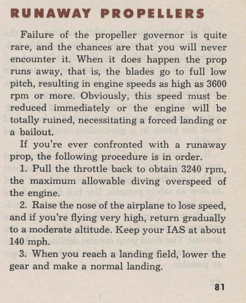
Worth mentioning the governing range on the P-51's Hamilton Standard prop gives a bit more leeway at higher speeds with 65 degrees for the high-pitch stop. The Jug's in the sim only governs to 48 degrees. Nevertheless, with any power on above 400mph in the jug it is next to impossible to keep the engine from overspeeding and causing trouble without manually reducing RPM by selecting a coarser setting with the manual mode. This is pretty silly that the entire range above 400 - 500 mph indicated (the number the 47 manual lists as the highest recommended dive speed below 25,000') requires the use of manual prop governing, lest you pull off all power and run the risk of MEB failure due to windmilling. As an aside, the P51 also has a higher-than-redline allowable RPM overspeed for diving (3240 RPM) as per page 81 of the training manual:
-
correct as-is Engine bearings damage too sensitive?
kablamoman replied to PL_Harpoon's topic in Bugs and Problems
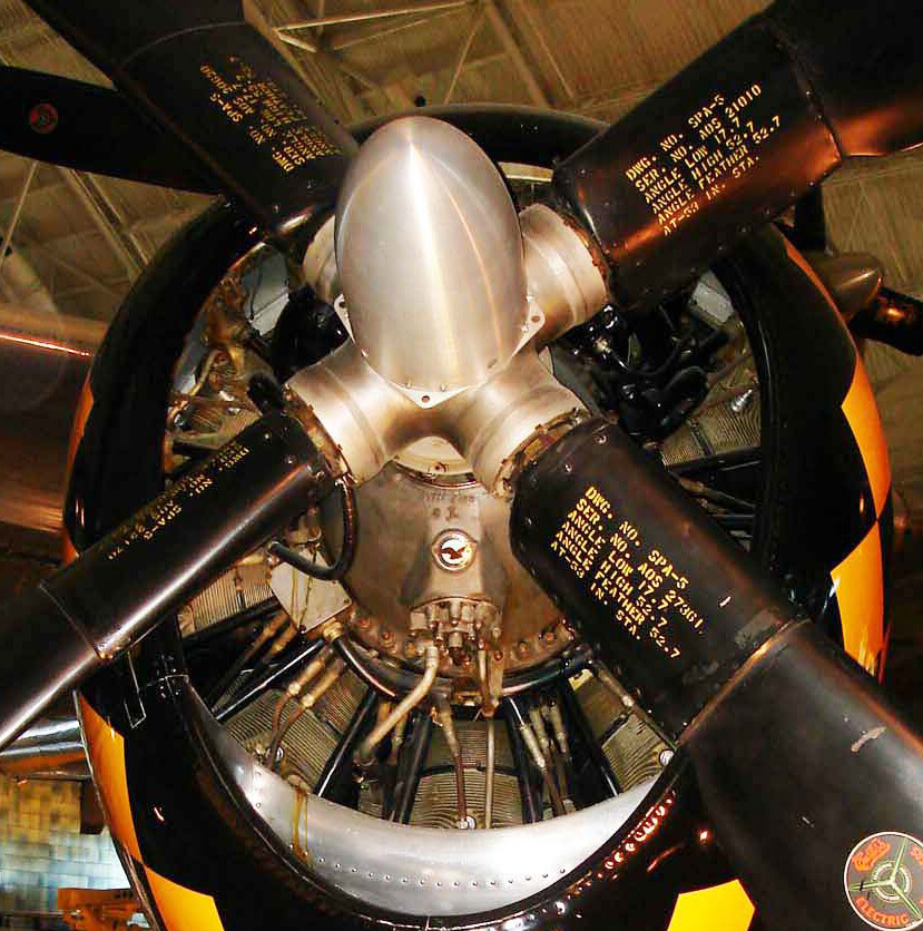
Just for fun, here's some random Curtiss electric jug images I could find where the prop angles were legible. You may notice that the ones with the 48.5 high angle limit like ours in-game have the same feather limit if it's also specified. One wonders how these machines would have been able to dive beyond 400 mph without the engine self-destructing:
-
correct as-is Engine bearings damage too sensitive?
kablamoman replied to PL_Harpoon's topic in Bugs and Problems
How about the fact that you can't exceed 400mph indicated without the RPM going over its redline and killing the engine when the prop is governing in automatic mode? There is simply something wrong with the way the engine and/or the prop is modeled: 1. The prop having a coarser "feather" limit in manual mode on a single-engine installation is suspect. The Curtiss electric prop hub has a separate "Feather" limit switch, but in single-engine installations the pitch angle for this should match that of the "Coarse" limit switch (the equivalent of a high-pitch stop). 2. As modeled in the sim right now, If you want to take advantage of the P-47's diving capabilities and fly within 100 mph of the redline airspeed, you have to switch the prop to manual mode and coarsen beyond the high limit to keep the engine from over speeding due to the windmilling prop. 3. Any kind of windmilling kills the engine way too fast. The standard practice of not allowing the prop to drive the engine with radials like the R-2800 was something they discovered post-war with airline operations trying to extend their TBOs with aircraft like the DC-6, and even then, it wasn't something that caused immediate and catastrophic engine failure. They certainly didn't care too much about it in their jugs during the war when time between overhaul was a secondary consideration to fighting in their aircraft. Can anybody cite specific mention of fragile main engine bearings or specific procedures to follow in pilot manuals to avoid the problem? There is certainly no mention of flipping the prop control to manual when diving. 4. Folks have already pointed out that 3050 RPM was noted in performance charts as the max permissible RPM overspeed in a dive. 5. Slightly different aspect of the module, but compressibility seems completely absent.