Charly_Owl
-
Posts
2298 -
Joined
-
Last visited
-
Days Won
21
Content Type
Profiles
Forums
Events
Everything posted by Charly_Owl
-

Polychop Christmas Update 2021
Charly_Owl replied to Polychop Simulations's topic in Polychop-Simulations
Does that mean with multicrew implemented as well? -
I know. I'd rather have Magnitude knock it out of the park than make a module that's just ok.
-
All I want for Christmas... is a F4UUUUUUUUU.
-
No mystery here, folks. I'll get to the Viper at some point, but there are other things on my to-do list that have higher priority. I'm just one guy with very limited spare time.
- 7 replies
-
- 16
-

-

-
- 1299 replies
-
- 14
-
-
-
That's very high praise coming from you, IronMike! Thanks!
-
The Tomcat Guide has now been updated with a brand new LANTIRN targeting pod section, including JESTER-specific procedures with it using laser-guided bombs. Enjoy!
- 58 replies
-
- 17
-
-
-
The Tomcat Guide has now been updated with a brand new LANTIRN targeting pod section, including JESTER-specific procedures with it using laser-guided bombs. Enjoy!
- 1299 replies
-
- 16
-
-
-
My hero!
-
Hi everyone! Time to learn the Mossie. Enjoy! Mudspike: https://www.mudspike.com/chucks-guides-dcs-dh-98-mosquito-fb-mk-vi/ Google Drive: https://drive.google.com/file/d/1T0lhlry8Y6GZNWsojlGsKCDY9AVa0S65/view?usp=sharing
-
The DH.98 Mosquito guide is now live! See first post.
-
Hi everyone! As some of you may already know, I will be releasing a new guide for the Mossie on November 9. I thought I would share what my impressions are of the module so far. 1 – The Visuals Right off the bat, Eagle Dynamics’ Mosquito has one of the prettiest cockpits I’ve seen yet. Kudos to whoever worked on it; this person deserves a year’s worth of the finest vodka. There is an amazing level of detail that’s unrivaled by any other simulation of the Mosquito. There are plenty of little things that show how much effort went into it, such as the radio station behind the navigator seat, the “magic eye” of the R1155 radio receiver set, the auxiliary oil supply controls behind the pilot seat, the drift periscope (not yet functional) in front of the navigator seat, the winch of the radio trailing antenna (which is, surprisingly, functional)… Overall, the cockpit fidelity is very good and you can click almost everything. We’re still missing the Very signal flare gun, but that is to be expected due to the nature of Early Access. The external model is equally satisfying. The damage model, despite being still a work-in-progress, shows convincing wood textures whenever you get hit by flak. The aircraft’s silhouette is a real looker, and there isn’t much I can say that a youtube video won’t show you in a better and more entertaining way. It’s a shame that the radio trailing antenna isn’t graphically modelled, because its effects on the radio is simulated. But even then… I’m kind of nitpicking. 2 – The Sounds The sounds are another great selling point of the module. Those Merlins sound fantastic. You can hear distinct differences between engine regimes, to a point where you can almost control aircraft power just by ear. I love how the sounds change as you turn your head around. The sound feedback of props gives you a quick indication whether your engine RPMs are synchronized or not; it’s usually a dead giveaway that the propeller governors are acting up due to damage or an incorrect throttle setting. Another thing worthy of mention is the remarkable implementation of old school WWII D/F (direction finding). While most DCS users are used to ADF (Automatic Direction Finding) beacons, the Mosquito navigator can have the rough bearing of a radio emitter by turning the loop antenna manually. The strength of the audio tone indicates how the antenna is oriented in relationship to the radio source. You basically turn the antenna until the signal source becomes very weak, then read the bearing on the antenna scale, and you’ve got a relative bearing of the radio emitter in relationship to the aircraft. There is also a SBA (Standard Beam Approach, which is sort of like a very early form of localizer) system that allows you to land at an airfield from a specific direction… but you know whether you are “on course” or not based on what audio signal you hear through the headset. “Dits” and “Dahs” indicate whether you are off to the left or the right of the runway centerline, while a steady tone indicates that you are lined up on the runway centerline. It’s very neat, very cool… But why on earth is it just available for the Caucasus map? This oversight angers me greatly. There are no NDB stations or Beam Approach (simulated with ILS frequencies, which need to be preset via the mission editor) on either the Normandy or the Channel map, which feels like a huge missed opportunity. D/F can use ground units transmitting on looped signals, but they are mostly unusable in multiplayer due to some bugs that have been flagged years ago. I’ve seen some users create some custom lua files to hardcode such NDBs and SBAs, but I beg Eagle Dynamics to implement those for World War II era maps. It does not make sense to not have navigation aids available for any of the era-appropriate maps. It would add a lot to the gameplay, and I cannot figure out why Eagle Dynamics offers a system that works but no navigation aids to use it with. You’re basically given a top-of-the-line steak knife to eat soup with… 3 – The Systems Systems-wise, the Mosquito isn’t very difficult to operate. The engine start-up procedure is quite straightforward, radiators are ON/OFF switches, the supercharger operation is primarily automatic… you just set throttle and RPM control levers to the required power setting, then fly the aircraft. You can actually feather the propellers, which has drastic impacts on aircraft aerodynamics whenever you lose an engine… but it’s not quite a get-out-of-jail-free-card since there are good chances that whatever damaged your engine may have damaged the oil system that drives the propeller blade angle as well. The fact that the fire extinguisher buttons are not implemented yet is a pretty big annoyance; whenever an engine fire develops, it’s pretty much a death sentence at the moment. The fact that the aircraft is made of wood means it burns very quickly, but it would be nice to have at least a small chance of saving the aircraft for that specific scenario where the engine catches fire but you have enough time to kill it before it spreads to other more combustible/vulnerable parts of the plane. Remarkably, the navigator’s radio station at the back of the plane is simulated to a deep level. Once you start playing with it in missions where you have to communicate with different units on different bands, you’ll quickly realize why the navigator and radio operator positions were needed. WWII radios are an obscure subject and a lot of research obviously went into the creation of the Mossie’s T1154/R1155 radio set. It would be nice to have an AI available to manage this for you in Single Player (or at least have a mode where an AI pilot can take over while you switch to the navigator seat). Another aspect I hope Eagle Dynamics works on is the navigator. It would be nice to have an interface like the one Heatblur Simulations implemented for the Viggen, which has an automatically generated kneeboard page of the flight plan with speeds, distances and headings. It would make the use of the drift periscope (which isn’t available yet) all the more relevant. A tool like a simulated analog flight computer (similar to the E6B used in most flight schools) would also bring a whole new dimension to the role of the navigator, making him even more useful. All of this makes me wish for bigger maps for WWII modules to create some actual navigation challenges. Compared to the Syria map, both the Normandy and the Channel map fall incredibly short in terms of size, yet with comparable price tags. Armament-wise, RP-3s (Rocket Projectiles) are not available yet, but the machineguns and cannons will shred pretty much anything that crosses your sight; the amount of firepower the Mossie packs is nothing to sneer at. Don’t underestimate the effect of a single well-placed burst! The bombs currently available have instant fuzes, which means that you are restricted to dive bombing profiles only. I have been told that implementing delayed bomb fuzes is a DCS core thing that still needs to be worked on (meaning that physics of a bomb skipping over water or hitting the ground both need to be modelled and validated), which makes ground attacks very restrictive. The Mosquito Fighter-Bomber’s bread and butter were low level strikes at tree-top level, which increased the survivability of the crew since it was less exposed to anti-air defences. However, dropping instant fuze bombs at those heights will likely blast your own aircraft out of existence. Therefore, the only thing you can do against hard targets is come in high and dive, which leaves you very exposed. This is one of the module’s Early Access limitations I hope gets solved quickly since it will have a direct impact on the survivability of the plane and the viability of ground attacks. 4 – Flight The takeoff roll of the Mosquito is something that needs some getting used to. You have two powerful engines turning in the same direction, which means you have to be very careful about how you increase power. It’s an interesting challenge. Taxiing and landing is a real breeze compared to the Spitfire simply because of the Mosquito’s undercarriage’s width. The torque the engines is manageable if you do it correctly, but keep in mind that there are situations where the aircraft can become unrecoverable. An engine failure late in the takeoff roll is one of these cases, as mentioned in numerous Mosquito pilot memoirs. When you’re in the air, the aircraft feels great. Now, I’m no Mosquito pilot, so I can’t comment on how realistic or not it “feels”. However, most of the handling characteristics seem in line with what I read in the Pilot Notes of the plane. One thing that could be improved is the sensitivity of the elevator trim wheel. At the moment, it's practically impossible to maintain level flight without constant stick input because the elevator trim wheel only moves in increments that allow you to be pitching slightly up or slightly down. The problem is basically that the increments of the wheel are too big. Most pilot manuals mention that you cannot really fly the aircraft hands off, but the elevator trim should at least be able to help a little, which it does not at the moment. To me, it seems like an easy fix (and some users edited the lua files by themselves) but this needs to come from Eagle Dynamics themselves. I experienced numerous one-engine landings in DCS and it’s interesting to see how physics are modelled. A feathered vs an unfeathered propeller has a big effect on drag; I’ve crashed a few planes simply by spinning while turning in the wrong direction with a propeller at the wrong angle. The general rule is that you want to “turn in the direction of the live engine”. I use the “Turn in the dead, you die” memory aid. You’ll also have to remember the following two memory aids. “Dead foot—dead engine” is used to assist in identifying the failed engine. You want to minimize aircraft slip as much as possible. “Raise the dead” is a reminder that the best climb performance is obtained with a very shallow bank, about 2° toward the operating engine. Therefore, the inoperative, or “dead” engine should be “raised” with a very slight bank. 5 – Fun What about the fun factor, though? Is it a fun plane? You bet. I think Eagle Dynamics captured something very special, something that I have yet to see in any other flight sim. The best way to enjoy the Mosquito is to fly with a friend in the other seat and plan your route together. Fly from a base in England and try to find your way to the Amiens prison (Operation Jericho) while flying 15 ft off the ground to avoid radar detection... you'll find that it's a great challenge that will test your skills. Teamwork is the name of the game. I can't wait to see what kind of missions are created for the Mosquito, It's a great plane to work with and it definitely gets the job done. Oh, and it's fast as hell. You won't outrun a late-war Bf109K4, but considering the payload you can carry, it's a vast improvement over what the RAF had at the beginning of the war. Overall, my impressions are quite favorable. If ED can get the bomb fuzes, fire extinguishers, elevator trim wheel sensitivity and the navigation aids sorted out in a timely fashion, I think we'll have a solid module to enjoy for the years to come.
- 6 replies
-
- 10
-
-
-
Yes, it will be updated eventually. However, it's relatively low priority at the moment since I've still got many ongoing projects that need to be wrapped up by the end of 2021. To me, the google drive links on the first post goes straight to the F-5 guide, not the C-101. Maybe try to flush your cache and try again?
-
Using the "8", and "0" keys, you can select which throttle you control. It's pretty useful for users who don't have enough axes. Using "9" controls both engines with a single throttle axis. Honestly, I'd keep it as is. It's pretty useful once you know what it's supposed to accomplish.
-
I have no idea. I know there was a recent update to google drive's policy, but it's out of my control. As an alternative, the pdfs hosted on Mudspike don't need any sort of account.
-
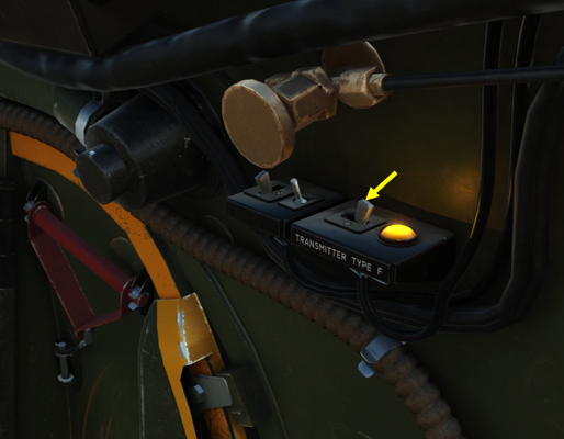
Hi folks, I have yet another question regarding the Mosquito. There's a "Type F" transmitter power switch next to the navigator seat. When set to ON (AFT), there is a warning light that keeps blinking, but I couldn't find any information about what this switch does exactly. Some speculate that it's some sort of IFF system, while others say it transmits a constant signal that can be homed on by other planes. So far, I couldn't find any information about what this switch is and what it does. Can the Eagle Dynamics team or any Mosquito expert give us an explanation for what this strange "Type F" switch is?

-
I have tried using the fire extinguishers on multiple occasions when I had an engine fire. Every time (out of about 20 tries), using the fire extinguisher buttons did nothing. The extinguishers are supposed to automatically engage when crash landing... but I have never seen them work properly in that scenario either.
-
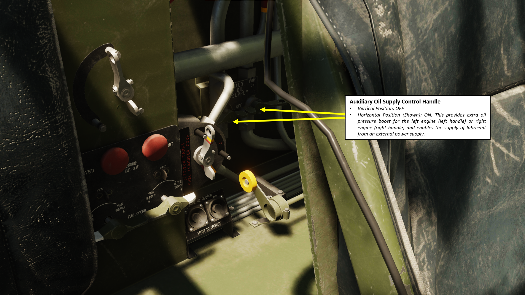
Hi folks! I noticed behind the pilot seat two Auxiliary Oil Supply Control handles. They appear to be clickable, however I couldn't find much information about them. In what cases should be use them? This isn't specified in any of the emergency procedures I could find.
-
Welcome to the club!
-
@No1sonukWould you mind if I sent you a couple of questions via private messages? I'm currently working on an operation guide for the T1154/R1155, but not being a radio expert myself there are a few basic questions I have on the whole system, and so far the explanations you have given in this thread seem to be exactly what I'm looking for.
-
It would be interesting to see what morse codes were used for each airfield in the area back in the WWII days. Does anyone have a reference for those?
-
Fortress Europe - WWII Multiplayer mission
Charly_Owl replied to Reflected's topic in User Created Missions General
A curious choice of blur...
-
reported earlier Can Not De-Fuel The Main Tanks.
Charly_Owl replied to bart's topic in Bugs and Problems
I can confirm that the same happens in Blue Flag Normandy. -
It still took 3+ years to get there.
-
The era of the 500+ pages long manuals is gone, I'm afraid. The A-10C and Ka-50 manuals are relics of the past for modules that are "complete" development-wise. With the accelerated development cycles and the nature of Early Access, I think you'll have to wait a few years before you get manuals as in-depth as the Ka-50 one for the Hind.