LJQCN101
-
Posts
509 -
Joined
-
Last visited
-
Days Won
1
Content Type
Profiles
Forums
Events
Everything posted by LJQCN101
-
Hi Wags, Just curious about the current roll rate limiter implementation. I thought the roll rate is linearly reduced above 15 deg AOA regardless of CAT I/III since it is to reduce inertia roll-coupling moment and prevent roll departure, together with other feedback such as dynamic pressure and elevator position (and possibly rudder position in later DFLCS versions)? I only have a pretty-old block 25 DFLCS diagram and there's a 134-ish deg/s decrease on maximum commanded roll rate when CAT III is selected. So according to your comment, this reduction only applies above 15 deg AOA?

-
Sorry for the delay. We're focusing on a final round of bug fixing and feature polishing for pre-QA code freeze so there may not be a video util this weekend.
-

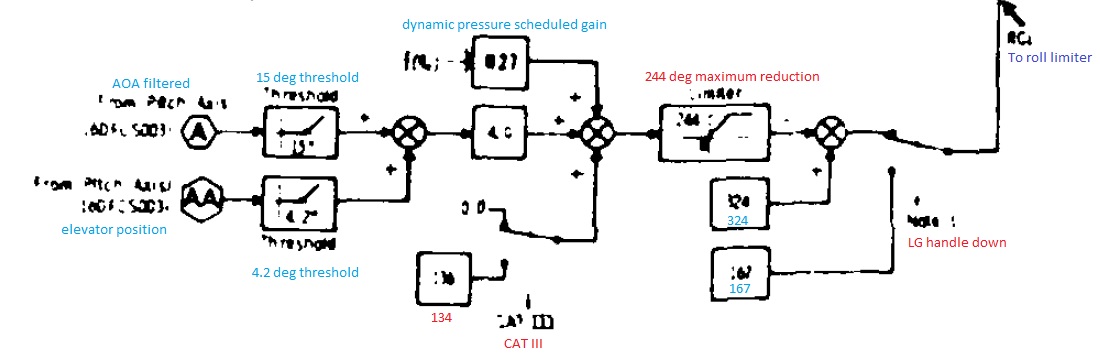
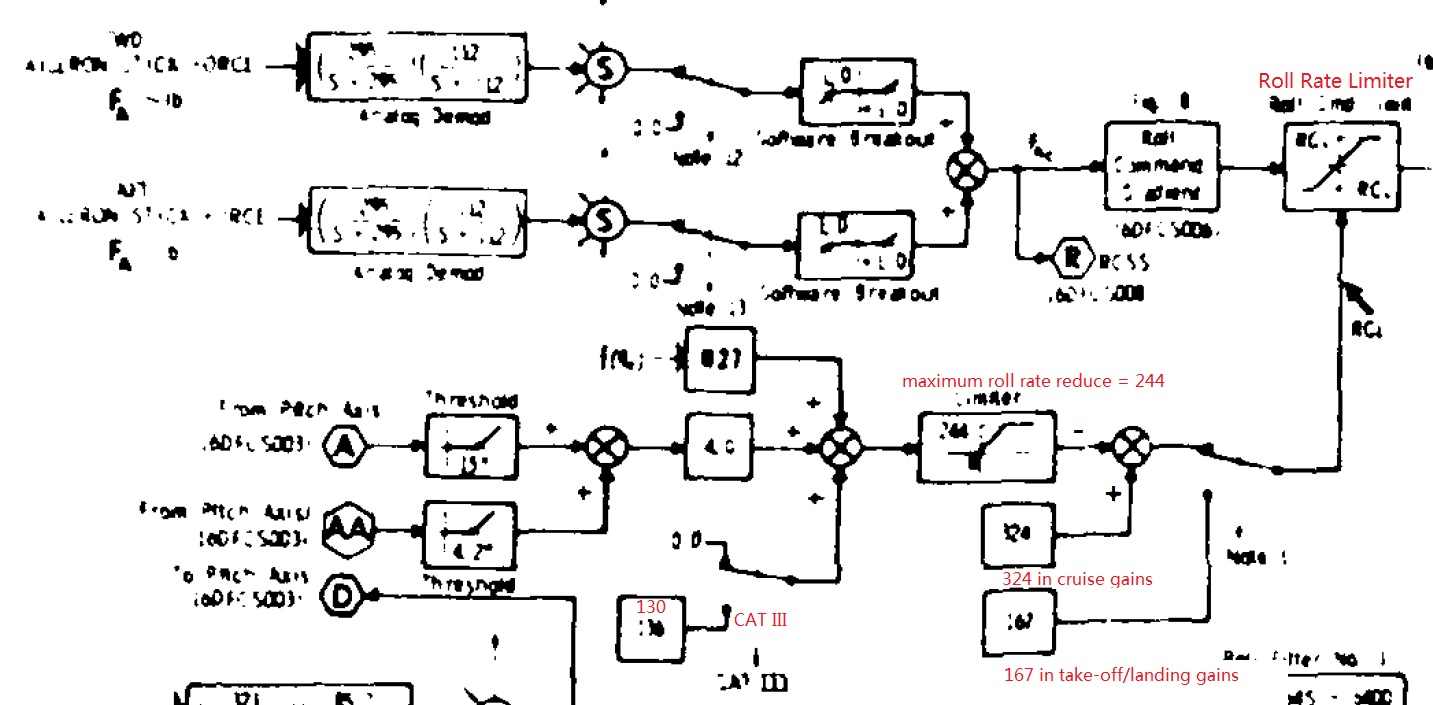
Possible bug - FCLS Roll axis Limiter in Cat III.
LJQCN101 replied to robgraham's topic in DCS: F-16C Viper
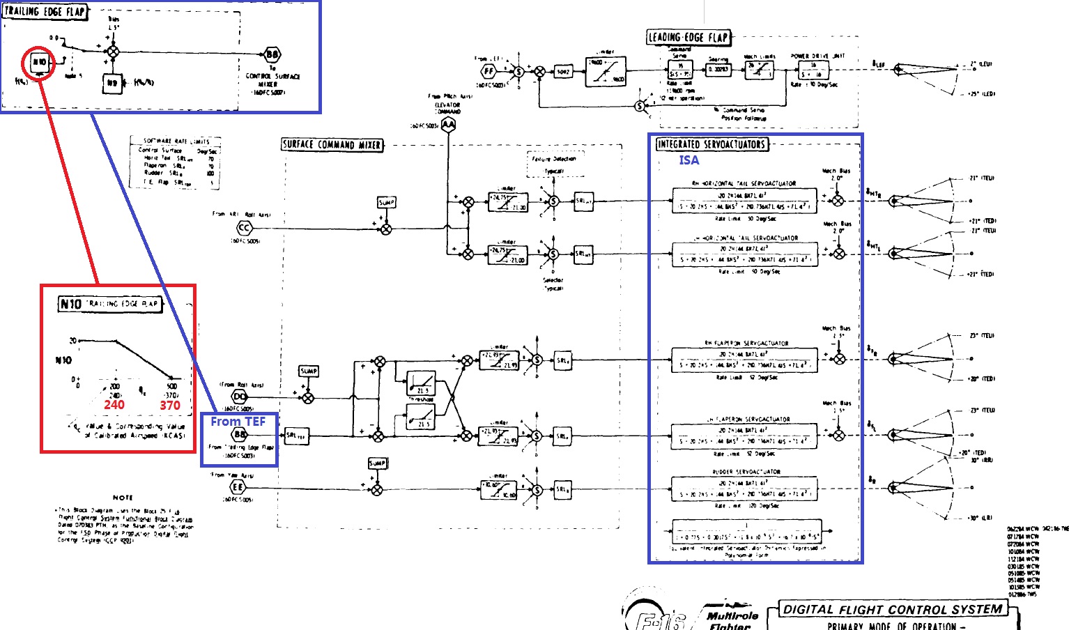
DFLCS can command a maximum of 324 deg/s roll rate in cruise gains, but that's the command value in the FLCS and you usually won't achieve that aerodynamically. Switching to CAT III will reduce the roll rate by 130, but the maximum roll rate reduction is limited to 244. That means in best cases you can command 324 - 130 = 194 deg/s, while in worst cases you can only command 324 - 224 = 80 deg/s. That's what you can tell from the very-hard-to-read DFLCS control block diagram (ref DTIC ADA 189675). And the DFLCS modelled in DCS F-16CM may or may not have the same value.
-
I guess you mean limit cycle oscillation?
-
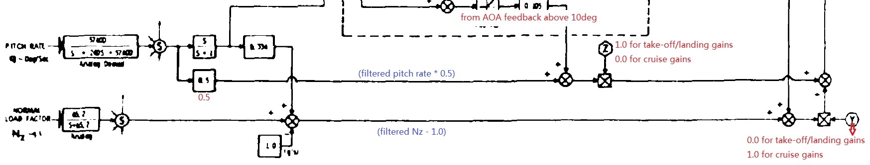
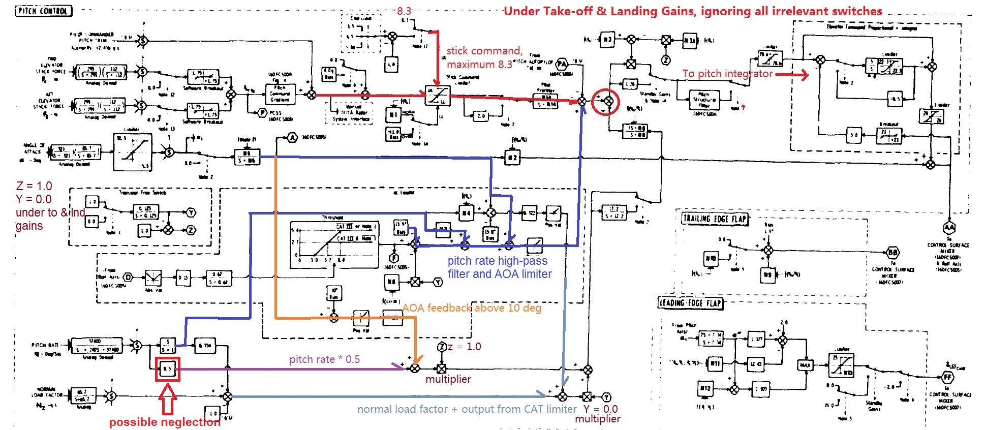
According to a DFLCS control block diagram of full scale development phase (quoted in DTIC ADA 189675 and 202599), a filtered pitch rate is multiplied by 0.5 under take-off & landing gains. Since max stick force is able to command 9G, which is an 8 in the system. By using pitch rate feedback in take-off & landing gains, the aircraft should be able to reach a pitch rate of 16 deg/s before AOA feedback kicks-in above 10 deg AOA. In the current implementation I was unable to pull a 16 deg/s pitch rate with max stick force. There could be a possible neglection of the 0.5 multiplier in the pitch rate feedback loop. It may be the reason why some players feel the aircraft too 'stiff' and can hardly pull it up when landing. EDIT: Full graph containing relevant info looks like this:
-
If the FLCS is coded line by line according to the control block diagram, then a set of curvature (command gradient) and deadzone (electrical break-out) is already included in the FLCS. Setting all curvature and deadzone to 0 should give you a realistic representation of control response.
-
The JF-17 pretty much uses the NATO definition. So IRL Mode 2/3 is unique to each aircraft, but in DCS it's hard to assign a unique code to each aircraft and list them in the briefing or somewhere else, so we'll let you decide/change your own code. Mode 1 can be team id, dependent on usage. Mode 6 is an updated version of Mode 4. Anyways we'll only implement the logic. How the codes are being used is up to the players. BTW Mode C provides altitude information. Mode 3 response is just a 4-digit code.
-
Red = Mode 1-3 got reply but code mismatch. Yellow = no response (including Mode 6 challenge failed) Green = code match or Mode 6 challenge passed
-
I'll share a little info from the ASM team. Radar scan patterns are still being tweaked ATM. For TWS, the supported scan patterns are: ±60°, 2 bar ±25°, 3 bar ±10°, 4 bar Correct. Correct. Those should be IFF symbols but it wouldn't show target vector. Still being tweaked. Would definitely be added. It actually shows the direction/distance from the cursor to HPT according to our source. Correct. In the video you provided, the AESA radar actually tracked 4 targets at the same time, but somehow kept the term DTT.
-
The JF-17 doesn't have any fuel flow indication unfortunately. It does have a FPAS-alike page though, but will be included later in the early access process. With 3 external tanks + 2 PL5E when doing a 0.8 mach cruise at 36000ft, FF can be as low as 1830lbs/h. But if you consider a whole climb, cruise and descend process, the total ferry range can reach 3500km. At sea level @ 1.0 mach with full AB in combat mode (engine work mode), FF is around 57000lbs/h.
-
How long has the JF-17 Module been under development?
LJQCN101 replied to MobiSev's topic in JF-17 Thunder
Roughly 3 years of EFM development and 2 years of ASM development. -
Wishlist for potential planes after JF-17
LJQCN101 replied to J-20's topic in Deka Ironwork Simulations
I'd personally give J-10A a vote. -
Not being representative of the USAF block 50 circa 2007 DFLCS, but according to the (quite dated) General Dynamic's control block diagram of Cruise Gains, there's only a transonic schedule for the TEF, which is a function of Qc/Ps. How later block DFLCS behaves need to be double checked as the -1 description stays true for the transonic flap schedule. EDIT: There do seems to be a TEF schedule for 240-370kts.
-
Change Wording: "Set SPI Generator" instead of "Make SPI"
LJQCN101 replied to Yurgon's topic in Bugs and Problems
I was also in an attempt to make sense of what the DoD manual said, though I do find some occurrence when it said "TGP is SPI" which is also not good for understanding. :lol: Anyways I don't have a preference as long as it can be explained in a paragraph (or more). -
FYI the first academic video will come in several days.
-
Change Wording: "Set SPI Generator" instead of "Make SPI"
LJQCN101 replied to Yurgon's topic in Bugs and Problems
I think the proper usage is "make something SPI", while "something" being an object/target /coordinate/point. i.e. make hooked object SPI, make last markpoint SPI or make HDC SPI. (These three are from the DoD manual). So for me I'm good with make TGP track-point SPI, make MAV target SPI, make TDC SPI, etc. But I personally won't call it make TGP SPI, make MAV SPI or make HUD SPI to avoid confusion. PS: I also think you can use 'slew/update SPI' from the F16 MLU manual. -
There's a modern one in the internet if you search 'Korea F16 Basic Employment Manual'. You can tell how the tactics described in The Art of the Kill get evolved and written into The Air Force Tactics, Techniques, and Procedures (AFTTP).
-
Just checked the older General Dynamics' control block diagram that the FLCS is still a g-command system in cruise gains. I believe the control scheme part of the DFLCS upgrade is mainly related to anti-spin logic. A less noticeable difference compared to the F18 FCS is that the short period pitch characteristics would be less wobbly but pitch response would be slightly slower, due to the presence of a derivative controller of pitch rate, which is to reduce the rate of change in pitch rate. For example, pulling from 1G to 5G would take more time than a F18. But a sudden release of the stick won't cause the nose to bounce back.
-
I guess the info for M5 tape in 2008 is by no means accessible. The only software version remains is the M4.2 tape which is the first common software for USAF CCIP jets. ref http://www.f-16.net/f-16_versions_article2.html
-
Is the F-16 HOTAS as intuitively as the A-10C?
LJQCN101 replied to Knock-Knock's topic in DCS: F-16C Viper
Yeah, CZ is an important function to clear all slew offsets (or called "system error"). IIRC in newer tapes, a TMS aft of <0.5 seconds commands a CZ, if the sensor is SOI and is not currently in any track mode. So you don't have to hit the MFD button. -
Is the F-16 HOTAS as intuitively as the A-10C?
LJQCN101 replied to Knock-Knock's topic in DCS: F-16C Viper
Expect difference in SOI and SPI control. In F16, you use DMS to cycle pages and set SOI, instead of coolie hat on the A10C throttle. SPI operation is automated so there isn't any control related to it. -
It’s a metaphor to our development process. As of system functionalities, both are in the module. BTW, you can't be both FAST and GC.
-
JF-17 Thunder Updates, Screenshots and Videos (NO DISCUSSION)
LJQCN101 replied to uboats's topic in JF-17 Thunder
DCS JF-17 EFM & FCS part 3: roll and yaw FCS -
Heard from pilot AMA that you can also check trimmed AOA in BIT-MI page?
-
Yes, you'll have multiple air to surface modes such as AGR, MAP, BCN, GMTI, SEA1, SEA2, TA, and WA. (planned)