Beamscanner
-
Posts
925 -
Joined
-
Last visited
-
Days Won
2
Content Type
Profiles
Forums
Events
Everything posted by Beamscanner
-
I dont think anyone has any idea how effective, or ineffective, the AIM-120 is. This all comes down to how comfortable the engineers would've with false targets and false target rejection. If they felt that the system was reasonably susceptible to false targets, they would've likely taken action to reduce the number of occurrences of false targets (increase the doppler notch bandwidth/velocity). (False targets from moving cars, spinning fans of AC units, etc) That being said, I think something that's being missed is that RWRs should not be as accurate as they currently are in DCS. Regardless of the exact doppler notch being used, the azimuth provided by the RWR shouldn't be so precise. Adding RNG to the azimuth of the RWR display would solve this problem without the need to play 'arm chair expert'. This RWR RNG would directly translate to variability in the probability of kill of the missile against a defending target. FYI 4 antennas performing amplitude comparison is not very precise.
-

no supporting references TGP AA mode features
Beamscanner replied to Beamscanner's topic in Wish List
There is a manual slew type called RATES that is supposed to function like the DCS AH-64 "Linear Motion Compensator". I believe this is missing from both the F-16 and F/A-18C. -
DCS: F-14 Patch Overview - New Autopilot & MP Seat Switching
Beamscanner replied to Cobra847's topic in DCS: F-14A & B
This is actually a very cool technique that nearly all PD radars use. Range is ambiguous in PD radar (HPRF). So range is resolved via other means (like FMR). However, when a track is initiated, typically the PD radar will Acquire the target (momentary action) Once acquired, perform a range resolve (measure the targets true range) (momentary action) Finally, it will continuously track the target in doppler only (without resolving range). It assumes target range based on the detected doppler motion from the point found in step #2. ie During track, the radar will know the targets range without having to measure it. -
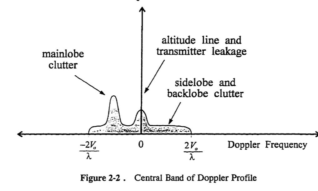
Amplitude. The graph is Amplitude over Radio Frequency. ("doppler spectrum" is just frequency, but more specifically the narrow band of frequency around the carrier frequency) A target could appear anywhere in the plot. But the clutter is somewhat predictable, hence the generic plot.
-
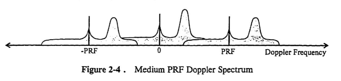
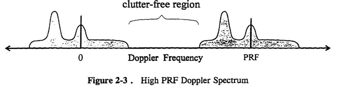
What should happen: Sidelobes increase as you lower your altitude. Sidelobes increase as you tilt your antenna downward. Sidelobes should decrease as you tilt your antenna upward. Sidelobes can effect both MPRF and HPRF in different ways. MPRF processes range and doppler, though these parameters are highly ambiguous when initially collected. MPRF has to cycle through a number of PRFs in order to resolve these ambiguities. That being said, MPRF will having sidelobe energy overlap targets in both range and doppler. Thus you should see reduced detection range at lower altitude, though I think low alt+look-up should have better range than high alt+look-down. HPRF should only be effected if the target is within the sidelobe clutter region. If the target is within the clutter free doppler region, the radar should experience little to zero performance loss. I think the problem is that ED is not simulating the above. I think ED is just applying blanket rules. (ie reduce range by X% if altitude is below Y) For the OP's incident, the sidelobe shouldn't of done much to hinder him. A high speed head to head closure would've likely put the target within the clutter free region of the doppler spectrum. And thus the sidelobes, while stronger due to low flight, don't even exist in that band of the frequency spectrum. Blanket rules like this wont work if you only use ownship position. I would say that they should include antenna tilt, target closure, and PRF selection in this calculation (with the possibility of zero performance loss in certain closure speeds in HPRF). But I think the best solution is the one Razbam and Heatblur have taken. Simulate radar detection. That way no blanket rules are used in places they shouldn't be.

- 37 replies
-
- 17
-

-

-
There is not absolute answer to this. What solutions Raytheon comes up with can be vastly different to what Northrop does. So, what I say below is a generalization. And not an exact truth for any one radar. Where does 'STT range is less than RWS' originally come from. Primarily it comes from the first pulse only analog radars from the 50s and 60s. These radars had lots of clutter in their scope as they did not perform doppler filtering or digital signal processing. With this radar type: Search mode detection range was a calculated average based on human performance to discern the target amongst the clutter. (target contrast) Tracking modes were accomplished via a range gate tracker, which held a target automatically by comparing the target reflection in a given range bin to adjacent bins in front of and behind the target. Due to noise that exists in all range bins, the target needs to have a SNR (signal to noise ratio) an order of magnitude greater than the noise in the adjacent range bins. The radar operator/Pilot would move a cursor (the range gate bracket) onto a given reflection, and only if that reflection had adequate contrast (ie good SNR) would a lock be obtained. The human eye can discern low contrast targets much better than 1960s analog circuitry could. Thus search range was farther than tracking range. Modern Radars are very different With modern pulse doppler radars with doppler filtering and digital signal processing, the search volume of the radar provides very high contrast (good SNR; hence much improved detection ranges). With these radars, the search mode performance is automatic and is not based on human perception. Thus on paper search and tracking modes should be the same. That being said, there is one tracking technique that can reduce STT performance in a modern airborne radar. But this can be overcome very easily. ---------- Mono-Pulse comparison is the process of splitting your antenna into 4 quadrants on receive. By doing so, you can compare the phase and amplitude of a return and determine a targets angle within the radars beam. (typically to a resolution of 1/10 of your radars 3dB beamwidth) The way it works is that your antenna is actually 4 quadrants that mix the incoming signal in various ways to create multiple output channels. These include: SUM (all 4 quadrants combine) Benefits are full antenna gain / max detection range Downside is that angular measurement is limited to antenna 3dB beamwidth The SUM channel is used to provide target range, doppler and angle (limited to beamwidth). Delta Azimuth (combine the 2 left side antenna quadrants, combine the 2 right side antenna quadrants. compare the signal between the two halves) Benefit is that you can compare the phase and amp between these 2 quadrants to improve azimuth measurement of the target. Downside is that you only use half of your antenna, and thus receive much weaker signals. Delta Elevation (combine the 2 top side antenna quadrants, combine the 2 bottom side antenna quadrants. compare the signal between the two halves) Benefit is that you can compare the phase and amp between these 2 quadrants to improve elevation measurement of the target. Downside is that you only use half of your antenna, and thus receive much weaker signals. ---------- That being said, there are important questions pertaining to this. When is Mono-pulse comparison used by radar X? (In STT only? in TWS and STT? in all modes?) Is a radar track not built unless the SUM and Delta channels detect the target? (ie will the system allow a trackfile to be built with only the SUM channel?) Does the radar use the detection of a target in the SUM channel to enhance/filter for the target in the Delta channels? (ie a lower threshold could be used in the Delta channels if you know where in range and doppler to look for the target) By far the simplest solution to such a problem is an extended dwell. STT vs scanning When a radar scans the sky it does so at a set interval. This interval limits how many pulses the radar can transmit and integrate down a given direction. Pulse integration improves SNR because background noise fluctuates a lot, while targets fluctuate only a little (were talking periods of milliseconds). Thus, the more pulses you transmit / integrate, the further you can see a target. If you cant increase your PRF, but still want to integrate more pulses, you have to slow down the scanning speed of your antenna. With fighter jets, this isn't always easy since the radar may need to scan a large volume while also revisiting a target periodically enough to maintain trackfile correlation (ie correlating raw hits to the same trackfile). The solution Once you're in STT, the radar has a LOT more time on target and can integrate many many more pulses on target as the antenna is fixated on the target and not searching around. This extra time on target means that the SNR will be vastly higher than in search mode, because its integration count is not as constrained. Factoid: Many modern radars can perform 'cued search', where in the radar receives external information on a target and then performs a very long dwell in that volume of sky. This reduces the need for volume search, and allows the radar to use much longer integration counts. TL/DR: Old analog "Pulse" radars: Search mode range > tracking range Early "Pulse Doppler" radars: Search mode range = tracking range (albeit with some hurdles) Modern radars: Search mode range < tracking range (assuming you know where to look) Reference: The best radar book ever, George Stimson's "Introduction to Airborne Radar"
- 44 replies
-
- 24
-
-
-
I think they've started work on the PRF audio. I believe an F-16 tone is played in this video update by Matt Wagner at 7:25. 7:00 you can see no contacts within the RWR scope. 7:25, just after he tells his wingman to engage, we hear a scanned radar sound (sounded pretty good to me). 7:38, as he pans out, we see a new contact in the RWR scope.
-
The dead zones in most DCS RWRs is pretty inaccurate as well... I made a thread on this years ago, but in short, RWR antennas are not cameras. They dont have a black and white FOV. their 3dB beamwidth is what is modeled into DCS. outside of that 3dB beamwidth, DCS stops them from working. IRL, RWRs work well outside of their 3dB beamwidth. They just arn't as sensitive. That being said, RWRs should work great against a missile 6 miles away from you while you even if you are in a 90degree bank. The only thing is that the bearings would be off as the amplitude comparison is ineffective in the vertical plane. ie It is unrealistic for you to lose missile indications when in a hard turn in DCS. and no, we are still waiting for the first official PRF audio simulation from ED. It will be worked on at some point for the DCS F-16 and hopefully back filled into the A-10, and F-5. (not holding my breath)
-
This is not an exploit. IRL the pilot would in fact be able to know if the enemy radar stopped looking his direction via the raw diamond audio (PRF audio). He would know this instantly. The RWR display holds the emitter for a few seconds to provide last know direction to the pilot. IC locking the lua file also prevents modders from adding high fidelity radar audio. If you really dont like this, the only thing that would need to be locked to prevent this (its not really an exploit IMO) is to move the "EmitterLiveTime" line to another lua file that gets locked. Keep in mind that PRF audio, which we will get, should only play when the emitter is actually looking at you. The audio would not play if the emitter had turned away. So this "exploit" is an actual tactic / piece of knowledge in the real jet that should also be in DCS. You would use the audio instead of the scope though. EDIT: There also other useful information provided to the pilot via RWR audio. For instance, the pilot would also be able to hear the enemy radar switch to a narrow scan. ie you could potentially determine if the radar switched from a wide RWS to a narrow TWS via the audio
-
The F-4's RWR is an iconic device that presented raw radar audio to the pilot. Heatblur is probably the best simulation developer I know of. However, I found their previous attempt at raw RWR audio in the DCS Viggen lacking in fidelity. I made a mock up scenario to illustrate what the F-4 pilot would of heard during an SA-2 detect to engage sequence. Though I've shortened it down to save time. I made these tones in audacity. (SA-2BF) Search to Track transition.wav Great video on these early RWRs:
-
investigating TGP loses track when radar drops track.
Beamscanner posted a topic in Bugs and Problems
The ATFLIR currently drops its track when the Radar drops its track. In my example, no other aircraft were locked onto by the radar. The ATFLIR should continue its point track, despite the radar dropping track. ATFIR.trk -
While operating GMT with INTL selected. In this mode, the radar performs ground mapping (a) and ground moving target detection (b) on an interleaved basis, alternating with the sweep of the search pattern. For instance, when sweeping right, the radar performs GMT. When sweeping left, the radar performs ground mapping. Issue: Data from sweep "a" does not persist while performing sweep "b". Just like the DCS F-16's GM/GMT INTL mode, data from sweep "a" should not be removed until the next sweep "a" is updates. Same goes for data from sweep "b". The intended effect: GMTs overlaid on top of map. (same as DCS F-16) Current effect: sliding door effect of data, where you cant easily make out or interpret landscape around a GMT. GMT.trk
-
Current release is missing: FCR/AIM-9 slaving to TGP TGP slant range (AA Mode) Laser ranging air targets TGP slewing
-
Is the radar going to get target extrapolation at any point? Seems pretty standard for modern radars in tracking modes (TWS/SAM/DTT/LTWS and datalink tracks)
- 1 reply
-
- 2
-
-
Looks awesome! So glad they went the direction they did with their radar simulation on the M2000.
-
After having reviewed some videos online, it seems that its pretty common to stabilize RWS bricks/hits in azimuth but maintain a static range on the display (display stabilized in range). (ie old bricks move left/right with ownship maneuvers, but don't come closer as you fly toward the brick) I saw this with the APG-63 and the APG-66, two separate air radar manufacturers. Its possible that pilots prefer this, as it makes it easier to move your curser onto the brick. If it was ground stabilized in range (ie the brick gradually moves closer as you fly toward it), it could make it more difficult for the pilot to chase it down with their cursor. Especially at close range. Unless someone has documentation, I'll assume that the current implementation is correct.
-
Changing AA modes (Normal/MRM/Dogfight) alters the brightness of the text displayed within/outside the image. I did not find this to be true before cycling through these modes. TGPbreaksLock.trk
- 1 reply
-
- 1
-
-
When tracking a target with the TGP in A-A mode, and with no radar tracks (no radar slaving), cycling between (Normal/MRM/Dogfight) drops the TGP only track. The TGP should not drop its A-A track unless commanded via TMS AFT or A-G mode is selected. TGPbreaksLock.trk
- 1 reply
-
- 1
-
-
In AA mode, the TGP does not revert back to its -3 elevation in front of the aircraft after dropping a radar track. Currently, the TGP will only move to 'ahead at -3° elevation' upon initial selection of A-A mode on the MFD. After that, when all tracks from the TGP and radar have been dropped, the TGP stares off in a random direction, and not "straight ahead at -3° elevation". Per the manual, "If the radar is not tracking an aerial target, the pod directs its line-of-sight straight ahead at -3° elevation" TGPbreaksLock.trk
- 1 reply
-
- 1
-
-
When entering SPOTLIGHT mode, the radar antenna does not move at max speed to center on the curser azimuth. It currently moves at normal RWS speed to the curser. It should slew at max speed allowed when entering Spotlight, similar to when entering SAM or STT. Once centered on the curser azimuth it should slow back down to normal search speed. SplotlightSlewSpeed.trk
-
The Radar will not remember RWS azimuth settings (A6, A3, etc) when exiting TWS or SAM. However, if you change your bar settings (B1-B4), it will remember your selected azimuth setting upon exiting TWS or SAM. RWSsettingexitingTWS.trk
- 1 reply
-
- 1
-
-
While in GM/GMT modes, with snow plow selected, and with an azimuth scan of 60 (A3) or 20 (A1) degrees, the radar will follow the last marked point instead of the nose of the aircraft. (ie the radar wont scan in front of the aircraft.) GM/GMT with a 120 degree (A6) scan works as it should. Its just A3 and A1 that don't work in Snow Plow. AGRsnowplow.trk
- 1 reply
-
- 1
-
-
ALR-56M contacts are not INS stabilized in the RWR scope or JHMCS. A fairly detailed description of the ALR-56M (A company webpage on the internet) states the following: [The ALR-56M is] "Compatible with numerous aircraft and EW avionics." [The ALR-56M Line Replaceable Units (LRUs) get] "Azimuth information about aircraft orientation allows for effective evasive maneuvering." http://www.dougalco.com/spar/apmil04.htm#rwr NoINSforRWR.trk
- 1 reply
-
- 3
-
-
-
I have some questions before I start reporting bugs. In regards to the TGP, should it be able to: display the TGP TD box in the HMD? display the Bull on TGP page? In regards to the radar, should it be able to: utilize a 120 degree scan (A6) in RWS-SAM? utilize Spotlight search in TWS? should RWS bricks be ground-stabilized in range and azimuth? or is the current implementation (display-stabilized in range/ground-stabilized in azimuth) correct?
-
No, I've had a busy few months. But I will have some free time early next year to work on the distorted audio. (I think the distorted sounds better too) Its just a lot of work to do it manually, as I dont know enough about audacity to apply the distortion automatically or via a pre-built effect. My interest is to get these to work in the Viper when they enable RWR handoff audio.. This is assuming they use pre-saved audio files that I can swap these out with. Here is my F-16 lock vs F-16 lock (with distortion). (F-16) Lock.ogg (F-16) Lock (distorted).ogg