Frederf
-
Posts
7593 -
Joined
-
Last visited
-
Days Won
3
Content Type
Profiles
Forums
Events
Everything posted by Frederf
-
Both
-

EHSI not showing range, when steerpoint selected?
Frederf replied to AngryViper.101's topic in DCS: F-16C Viper
If it is it would be so small that noticing might be hard. I think I did some GPS off drift checks and it looked like there was a difference in at least station keeping. I didn't dozens of tests to rule out RNG though. -
The procedure is most likely 1500' AAL or above aerodrome level. Traffic pattern height is often stipulated in a way that it's a certain value, possibly rounded, and referenced baro QNH. The actual legal height should be issued by the controlling agency. Usually it's the airport elevation (highest point on the field regardless of elevations of any bit of runway or approach area) plus a number. In any case it's read from a document. How picky anyone is about a few feet in practice is another issue.
-
EHSI not showing range, when steerpoint selected?
Frederf replied to AngryViper.101's topic in DCS: F-16C Viper
Normal is higher quality in some regards even 10 compared to 10. Plus a stored has to be prepared. The INS is aligned fully and shut down without flying and then the airplane cannot be moved at all. -
reported earlier targets disappear when switching from RWS to TWS
Frederf replied to dutchili's topic in Bugs and Problems
Radar is always making and maintaining tracks in either mode. It takes a few detections to make a track. If the track exists when switching to TWS then it will be displayed immediately. -
Yes.
-
reported earlier targets disappear when switching from RWS to TWS
Frederf replied to dutchili's topic in Bugs and Problems
The reason the targets weren't shown was because your radar was aiming below them. They weren't detected in both RWS and TWS for approximately 45 seconds in the middle of the engagement. 08:00:10 target detected only once (RWS) 08:00:13 contact mark degrades into 1st stage history 08:00:26 last history contact times out 08:00:37 switched to TWS 08:01:01 detected and bugged track. Here's the exact same track but taking over and aiming the antenna a few degrees higher. radar targets not shown2.trk -
Biggest effect was probably simply the terrain is not flat. It's perfectly possible to be 1500' above the airport but only 1300' above a hill below you on approach. The terrain to the NW of the field is commonly in the 2400-2500s elevation even within 3 miles. But I still want to impress upon you that barometric altimeters do not show true altitude in general, even when calibrated. A calibrated altimeter only reads correct at the level it was calibrated for. Everywhere else it's wrong. If you set QNH at a high elevation airport on a cold or hot day and fly up to 20,000' instrument reading you will be no where near 20,000' true altitude. Here's an example of QNH at two different airports with "QNH 29.92" in the briefing in all six cases and the only difference being temperature and airport elevation. Notice at Beslan when hot/cold the real QNH for that airport is wildly different than the briefing value. -5°C SLT Beslan (elevation 1729') QNH is 29.77'' Batumi (elevation 33') QNH is 29.92'' 15°C SLT Beslan (elevation 1729') QNH is 29.92'' Batumi (elevation 33') QNH is 29.92'' 35°C SLT Beslan (elevation 1729') QNH is 30.04'' Batumi (elevation 33') QNH is 29.92'' Notice that with standard SLP and various temperatures the QNH at a sea level airport is effectively unchanged. But the farther away you get from the calibration point temperature matters a great deal. I'll try to replicate the circumstance. Gaziantep runway surface actually varies considerably in elevation from 2289' at the RWY10 numbers to 2196' at the RWY28 numbers. The airdrome data of 2287' elevation must be indexed off the RWY10 end. At the default runway spawn location the A-10C2 is altitude 2204' on a spot of terrain 2197'. The airplane's sensor port is 6-7' above the tire contact surface. I have chosen the default +20°C SLT and 30.16''Hg SLP. QNH to achieve altimeter reading for surface under airplane and airplane reported true altitude are 30.18'' and 30.19'' respectively. If I set QNH from the briefing blindly as 30.16'' I get a reading of 2180' or so on the ground. The terrain is anything but flat not only on the approach to the runway but even the runway itself. Two hundred feet of discrepancies could happen easily just by valleys and hills. But just to illustrate the altimeter/radalt exactly I'll fly over the same takeoff spot at 3697' true altitude and note the readings. At 3695' true alt over a point on the ground 2197' elevation I have baro reading 3675' (QNH 3019'') and 1500R radalt. Adjusting Kollsman to 30.16 baro reads 3650'.
-
CZ and the sighting point rotary are the same wherever they're found. It doesn't matter where you activate it (FCR or TGP), they all do the same thing. When you slew a sensor away from a steerpoint you introduce slews into the system which stay until erased. CZ eliminates all the slews in the system. TMS down in TGP you'll notice puts the sensor back onto the steerpoint, that's CZ too. The "TGT" shows what the current sighting point is. Sighting point is the place your sensor is looking at which can be different than the target. For the most part you won't have to worry about it. Depending on the situation this can be "TGT" for target or "STP" which is basically "TGT" for non-attack modes, "OA1" or "OA2" for OAPs, "IP" or "RP" in VIP or VRP modes, and even blank for situations where there is no sighting point allowed like in snowplow. A lot of the time if you don't do special preparation you won't have any options for sighting point except the one (usually STP or TGT or blank). TMS right is area track. Except when Maverick missiles are active it does something else, commanding a reattempted missile handoff. All sensors are slaved to the same point at all times. When you move one the others move too. AG modes fall into two categories: visual and preplanned. Visual there's no way to put sensors back to steerpoint because visual attack modes are not steerpoint-centric. In preplanned modes, CZ.
-
Multiple tankers - but only one reachable in comms menu?
Frederf replied to Toumal's topic in Mission Editor
Only tankers which are currently participating in the tanker task show up in the menu. It's possible for a KC-135 to be flying around which is not a tanker because it's not doing that job at that moment. -
DCS does not give QNH. The ATC gives QFE and the briefing gives QFF which it labels as QNH. You will find that at airport surface setting value from briefing "QNH" (QFF) will not equal airport elevation. The difference depends proportionally on vertical distance from sea level and temperature difference from standard. A high altitude airport and hot temperature will indicate you are much below known airport elevation. Remember that altimeters have a calibration point where they are correct. Everywhere else they may not be. QFE reads zero at airport surface QNH reads airport elevation at airport surface QFF reads zero at mean sea level Because QFE and QNH are calibrated to a specific airport it is impossible to have a universal value for all airports. There is no such thing as "the QNH" only "a QNH for this particular airport."
-
For their original purpose you need the offset between the aimpoint and the target. I guess you could put a map marker on a JTAC or other target location then measure to a nearby map object as your aimpoint and offset. Then on run in refine the aim off that major map object. A lot of the utility of offset aiming is in refining the INS which goes away in a millimeter perfect GPS environment. Back in the 70s or 80s when drift could be thousands of feet and you were toss bombing an area target often several days in a row just to have a good chance of a hit it made more sense. Apart from their original purpose OAPs and other offset marks can be used as marks in the sky to visually fly through when doing certain rapid precise maneuvers like pop up attacks or even air show maneuvers. As interesting as the system is, without offboard targeting of the appropriate form and significant INS drift, it's not likely to be oft used.
-
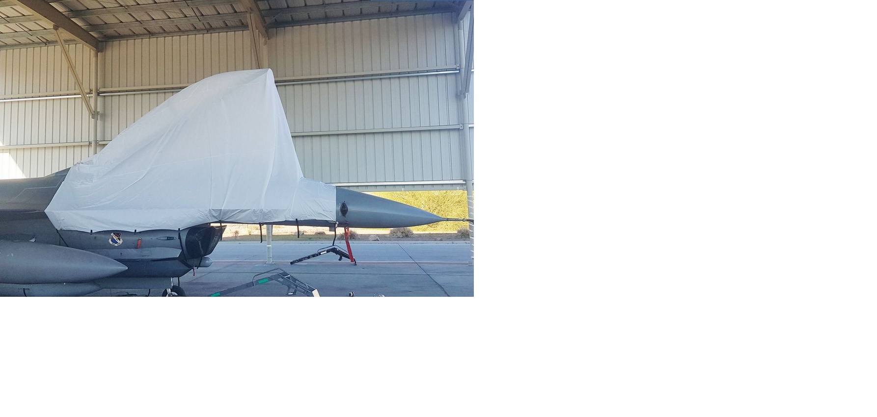
I was noting how the AI used it. It shines the landing light to drive around and then switch to the taxi light for takeoff.
-
Correct observation, the smaller-upper light is the taxi light and the larger-lower light is the landing light.
-
need track replay TGP Blank after Timing Out
Frederf replied to drspankle's topic in Bugs and Problems
That's the menu where you pick which mode. If STBY is shown next to the OSB1 label (OSB are 1-20 increasing clockwise from the top row, left side) then that's the mode the pod is currently in. To change mode you would press: OSB 1 (STBY) to enter the selection menu <as in picture above> OSB 6 A-G to enter A-G mode -
I've looked at the FLCS control law branch for the roll channel and my (limited) understanding is that it's basically an N-order differential equation with competing rates. So an upset moment say from an asymmetrical store config would be effectively dampened but not eliminated. E.g. as the roll rate gets smaller so does the gain so the roll rate is less than if the ailerons/tailerons were simply bolted neutral but not hard zero like a PID-controlled autopilot hold. So bomb falls off, roll acceleration is high and with some lag the counter rate blends in slowing it but long term it's still going to spiral until some trim is added. That's my rough understanding.
-
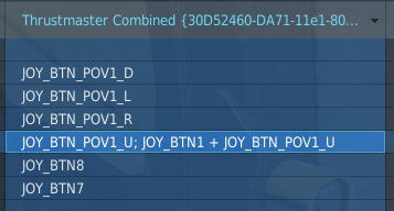
I was able to make coolie and slew separate. Make sure when you add the command of control+modifier that you erase the original command or they'll both be bound. See example:

-
Rudder trim is used. One can see what the airplane could have been built to do I guess by engaging the attitude autopilot. That holds a particular bank angle.
-
I know of no version of FLCS which does this. If it always compensated for roll why would there be roll trim?
-
Customized Cockpit Selects the set of cockpit artwork which is in various languages. Default resembles the actual airplane in French. English adjusts text labels as they might appear for an English-speaking air force. Disable Gyro Drift The rel INS due to its nature will not perfectly track the position of the airplane over time. This option causes the INS ownship assumed position to always be equal to actual position. Automatic fuel detot The fuel gauge (right side) operates by being manually set by the pilot and only automatically reducing fuel burned. Thus realistically the pilot must adjust this value as needed to ensure it reads accurately such as when jettisoning full fuel tanks, refueling midair or on the ground, or similar. With the option set the pilot has no control over the manual fuel gauge and it will always read the actual total amount. External tank refuel fix Normally refueling does not change the fuel quantity in external tanks. With this option enabled fuel in external tanks is adjusted when internal fueling is requested. For example when 100% is selected on the slider and an external tank is present (not the 'empty' kind) that tank will normally be filled as well. Radar senses map objects Presumably determines if the radar sees static type objects placed in the mission editor. But with testing I count not find a situation where an object was not shown with the option off. Probably this is added for performance reasons. Radar full asynchronous update (beta) New radar modeling where radar simulation is run asynchronous to other systems? Radios PTT toggles menu New controls were added which cause the airplane to react as if the push-to-talk buttons on the throttle were pressed with the white text menu only appearing if this option is enabled. This was likely done for compatibility with the SRS multiplayer voice communication software. Realistic frequency repeater When enabled the frequency repeater (green LCD above ADI) behaves realistically showing only the green radio. When disabled the repeater works as previously showing both radio frequencies. Enlarge small VTB items (%) The radar scope symbols can be increased up to 125% of their normal size. Realistic VTB cone of vision Due to the construction the radar scope it is not readable when looked at from off-axis position. Disabling the option removes the effect allowing view from all angles. VTB cone of vision size VTB cone of vision height The limited view cone is modeled as a circular mask. The size is the diameter of the circle. Height is (possibly) the angle of the axis of the display. Show PCN hidden digit entry message When enabled and entering latitude/longitude figures a hint will display on screen showing the full figure entered. Otherwise the pilot will have to use the cockpit display in which the last two digits of precision are invisible. Throttle cutoff detent Used for assigning axis input to throttle handle motion between off and idle position. This is useful for controllers which have a distinct off position and axis reporting for the range of motion between. This is the axis value which must be exceeded before the throttle handle will reach the idle position. Throttle afterburner detent Axis input value that corresponds to the transition from military to afterburning thrust. This is useful for controllers with a distinct afterburner axis range. Adjust speed of mouse wheel Sensitivity of cockpit controls to mouse wheel input. This is useful for various mouse wheel type input, namely VR equipment.
- 5 replies
-
- 12
-

-

-
It's available to any country. Cold War lasted a while but A2A I think it performs well, mostly as an interceptor. It benefits greatly on external direction and radar coverage. Against a Mirage 2000 or similar big disadvantage. The AG capability is significant. I wouldn't say hard but more like less tolerant of creativity on the part of the pilot. If you fly it by the book it has little troubles. If you have the "nuts to the manual I'm just going to turn on every switch before the engine" personality you won't have a good time.
-
There is a parking brake. All brakes require battery power and toe brakes require power to the FLCS which can be done on battery power (if relays are closed). It's not for actual parking like getting out and going to bed. Interestingly toe press continuous hold depletes accumulator while parking brake does not. So during the interval between parking brake available and HYD B to pressure I guess the best technique is to rely on the chocks but be ready to engage brakes (parking if FLCS not powered, toe available if FLCS powered) if anything goes wrong. The reason is that brakes pull pressure from the #2 accumulator so holding toe brakes depletes accumulator pressure which would be used for a start2 start. If you had to start without chocks for whatever reason the safest would be to engage parking brake, don't touch toe brakes, and start via start1. That way the brake accumulator isn't used to start and it won't deplete like holding toes.
-
cannot reproduce Mavericks - VIS mode not ground stabilized
Frederf replied to SmoglessPanic's topic in DCS: F-16C Viper
Indeed, while one might see why it might be undesirable to immediately return to slave on the first command, documentation says otherwise. I am reading in two places that TMS aft tells Maverick to reject target and return to slave SPI LOS. That suggests break track may immediately return to slave/SPI LOS. It could be that it requires undesignating twice to break track and then return to slave. The software in the airplane has undergone changes in history. The earlier versions would switch SOI WPN on the first designate of the TD box on HUD. Later versions would (when using HMCS) add an extra TMS forward after grounding the TD before SOI WPN. Even later versions had the extra designation for HUD as well. I think this version is late enough to have the universal middle stage. I'm suspicious of the HMCS ground designation skipping directly to WPN SOI as real. I see that in DCS both HUD SOI and HMCS SOI EO VIS skips SOI straight to WPN on the first designate instead of requiring a second. In any case the TD box once grounded is the spot which all missiles are slaved so after firing one the next one should already be aimed at it. That isn't happening. Instead the next missile stares straight ahead. When WPN is selected manually and slewed the LOS circle is not appearing. That seems wrong. -
Align after engine start per documented operating procedures Don't use parking brake during engine start, chocks (real life) and feet holding brakes (enough in DCS) You can move the airplane during the latter portion of the alignment You may want to check the right_cntl+enter display to see throttle position. Movement under idle throttle is possible but should be a rarity, especially in DCS.
-
This is a good question which took me a while to answer. The lateral extent of each UTM zone is defined by lines of longitude but the grid orientation and metric interval associated with each zone is not. Grid north is the direction on the map which increases northing without changing easting. UTM grids are constant in size and spacings of longitudes are not. Thus lines of constant easting and lines of constant longitude can't be parallel. Longitudes are fractional as in 10°30' is half way between 10° and 11° regardless of how much distance separates them. UTM grids are not, an easting is 100,000m lateral regardless of how far spaced longitudes are.