All Activity
- Past hour
-
Is link to Bing search of a document ok?
-
Folks please do not post documents without sharing a public link that shows it is 100% for the public. Please read our 1.16 rule thank you
-
Бортовой комплекс самолетовождения, прицеливания и управления вооружением самолета МИГ-29Б - Поиск I mean, there is a graph of blanking signal radar casts on itself to not always show a white wall, radar transmitter and receiver never work simultaneously, although frequency of switch is very high. And what connects radar to SPO-15 is not a flimsy bool singnal cable but a big shielded high frequency cable. I can only thinking of HPRF "Front mode" self blanking.
-
Sorry, this is a core DcS issue and ED should be looking at it. The end mission button is not supposed to be broken just because an AI took off from a carrier, and the solution is not to delete this AI but to make sure that button always works like it’s supposed to. @[ED]Ben BTW I never in my life had this problem, only some users do. There must be something else, something different. So I can’t even experiment and test what works and what doesn’t because it never happens to me.
-
You want to say the +1 were adding anything to the discussion? They were too lazy to even write the current sum. And calling people, who demand news after they were told the news will come when the team is ready to share, entitled, is not exactly an insult.
-

DCS MiG-29A Flight performance and air drag seems weird
The Gryphon replied to HoMeBoY's topic in DCS: MiG-29A Fulcrum
Yes I exactly. If you compare the F-14 and MIG-29, they have both two engines, but the MIG is much smaller (and has less weight) that could explain it. MIG-29A must be the smallest aircraft in DCS with two engines mounted? True -

DCS MiG-29A Flight performance and air drag seems weird
Hiob replied to HoMeBoY's topic in DCS: MiG-29A Fulcrum
True, but with gear and flaps down, it should still bleed speed like crazy (in idle). -
Thanks we will take a look, the controls indicator is fixed internally and will be in a future update.
-

DCS MiG-29A Flight performance and air drag seems weird
primus_TR replied to HoMeBoY's topic in DCS: MiG-29A Fulcrum
Well, the 29a can reach Mach 2.3 for a reason. -
DCS MiG-29A Flight performance and air drag seems weird
The Gryphon replied to HoMeBoY's topic in DCS: MiG-29A Fulcrum
If I recal correctly, isn't MIG-29A a pretty small and light aircraft (like the F-16) but in comparision with the F-16 it has two engines, perhaps it explains the high thrust to weight ratio. The MIG-29 has a pretty wide fuselage blended with large wings, perhaps that explains the high lift? -
HB did that with the F4E (tickbox for reference aircraft), and I think it is a good thing to have that as an option.
-
Fixed: Missing HOTAS AG Gun Strafe Toggle. Where to find ?
Tenkom replied to -=Shin=-'s topic in DCS: F-16C Viper
I noticed when using this new shortcut the SMS page didn't go into "Strafe mode" like it does when you click the top left OSB button. Is this correct? -
DCS MiG-29A Flight performance and air drag seems weird
Hiob replied to HoMeBoY's topic in DCS: MiG-29A Fulcrum
Bleeding speed in the Viper is a piece of cake. Especially when dirty. Try a back to back comparison with the Fulcrum. From my (very subjective) pov, the Viper feels "right", whereas the Fulcrum feels like it was covered in butter. Very slippery. -

reported edCore.dll Crash - b2DynamicTree::RemoveLeaf + 0xBB
travissgrey replied to Heart8reaker's topic in Game Crash
Same problem, same error, several crashes on both Germany and Caucasus. dcs.log -
DCS MiG-29A Flight performance and air drag seems weird
primus_TR replied to HoMeBoY's topic in DCS: MiG-29A Fulcrum
Very similar to F16, which is not surprising in my opinion. -
DCS MiG-29A Flight performance and air drag seems weird
Hiob replied to HoMeBoY's topic in DCS: MiG-29A Fulcrum
The high lift and thrust seem consistent with what the Fulcrum is known for (I don't have any data, just from hearsay).... However, I would agree, that it seems almost impossible (in comparison) to bleed speed. -
I'm seeing the same issue here after C&D start-up. I run the AFCS test with no problems except that I have to trim aileron and elevator after it's done. But even though these axis are indicated as neutral, after take-off it banks a bit to the left. Have no idea why this is happening but I just use the trimmer reset button as suggested above. But I don't get why I'm having this issue as well.
-

DCS MiG-29A Flight performance and air drag seems weird
BIGNEWY replied to HoMeBoY's topic in DCS: MiG-29A Fulcrum
No worries, we are happy to look at the track and investigate. -
Can we see any documents that state that spo And radar can work simultaneously?
-
(fixed) Tel Nof "detour" taxi routes about spots 44-96
western_JPN replied to western_JPN's topic in Bugs and Problems
Hi. This bug looks almost fixed now in version 2.9.20 .15010 patch. Only two or three slots get another new detour bug though, I'll report it in the new topic. -
That's another way I didn't test, important is that it is working
-
That's the serious problem that people don't understand: when aircraft landed on an aircraft carrier, they were moved by the ground crew. The pilot shut down the aircraft as soon as they landed and left the area of the landing cables. They weren't even "parked"; they were simply stored forward on the deck until the landing cycle ended or move down to the hangars and the deck crew redistributed them (this is seen in certain "strategic game" involving World War II aircraft carriers). Takeoffs and landings were planned (which took a long time), and the aircraft were deployed from bow to stern and to the hangar, or vice versa. The pilots never intervened, and when they took off, it was simply from their takeoff positions, with a very short taxi to align, nothing more (nothing like the SuperCarrier). Furthermore, the use of catapults was normally "very rare," and less so in large attacks.
-
DCS MiG-29A Flight performance and air drag seems weird
HoMeBoY replied to HoMeBoY's topic in DCS: MiG-29A Fulcrum
Hi thanks for the reply. Tonight I will record a client track from the Caucasus Free Flight and Landing from Final Approach instant missions and leave some comments about my experience. I am not "claiming anything", it was rather to get other opinions from the community. Even if I don't compare modules, it will feel overpowered in terms of pure flying performances when joining an MP server with diverse adversaries. Lastly, I understand it just came out in EA and I am just hoping it will reach the same level of polish as other modules. Something that the MiG29 is already doing better than the Phantom for example are the water drops effect on the canopy. -
fixed internally AGM -154C's not hitting their target
BIGNEWY replied to boo_n_817's topic in Weapon Bugs
Hi, this is fixed internally and will be in a future patch once QA checks are completed, thank you -
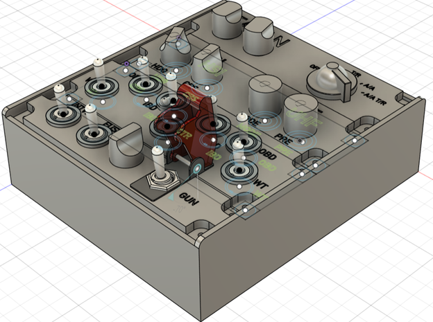
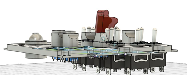
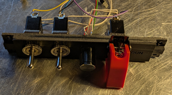
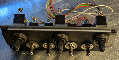
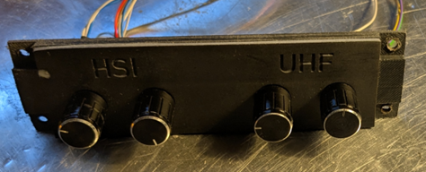
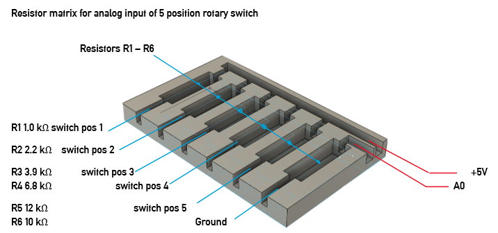
I loooove flying the Northrop F-5E in DCS. As I am purely in VR, input of controls with my mouse is often too slow and clumsy. While using the MOZA MTP throttle and MTLP panel with a Rhino FFB base and WinWing ViperAce stick I found that I still lack certain controls to enjoy flying and fighting in the F-5. Looking around I found nothing really satisfying to solve my problem. Finally, I decided to find a solution on my own. The plan: Build a button box for · TACAN modes, tens, ones, X/Y · UHF modes, presets · HSI input HDG & CRS · Stations select 7 stations · Interval setting 3 positions · Bomb fuse 3 positions · Weapon mode selector · GUN on and off My take on this was to use · TACAN: one 5-position selector, two rotary encoder · UHF: two rotary encoders · HSI: two rotary encoders · Stations: seven ON/OFF rocker switches · Interval: one ON/OFF/ON rocker switch · Fuse: one ON/OFF/ON rocker switch · WP mode one rotary encoder · GUN: one ON/OFF rocker switch Two Arduino Leonardo controllers to emulate two USB game controllers for Windows. Overall split across 2x Arduino Leonardo So that all inputs fit comfortably on the pins (and you avoid serial conflicts), I choose this distribution: Leonardo A (Hardy’s F-5E ButtonBox A): 5 rotary encoders with pushbutton 5×(A/B) = 10 lines + 5×Push = 5 lines ⇒ 15 pins. 1× 5-position selector switch, 1 analog pin (via resistor network) Leonardo B (Hardy’s F-5E ButtonBox B): 2 rotary encoders with push, 6 pins 8× ON-OFF rocker, 8 pins 2× ON-OFF-ON rocker, 4 pins The Box The box needed to be printed on my Anycubic Kobra 2PRO and Photon Mono 2. So, I drafted the Box and panels with fusion, to export stl files and slice them. My filament printer caused some heat deformation of the box and the base plate. Therefore, I had to split the large bodies to obtain separate STL files for four bodies of the base plate and two bodies of the box. The plates were also split, with the lower part printed using the FDM process and the upper part printed using the resin process for better resolution. The parts were glued together. Panel one: bomb interval, fuse setting, external stores rotary switch, gun/cam switch with cover Panel two: armament position selector switches Panel three: HSI heading and CRS, AN/ARC-164 UHF mode and frequency mode Panel four: TACAN tens, ones, X/Y, modes Wiring General wiring diagram (for all buttons/switches) One side of each switch to GND, the other side to an input with INPUT_PULLUP. Logic: LOW = active, HIGH = inactive. Also connected encoder A/B to GND (A and B each to inputs with INPUT_PULLUP), common ground of the encoder to GND. Ground routing: one clean star ground (GND bus) per board. No need to ground the two boards together - both have a common ground via USB anyway. 5-position selector switch as analog value. Instead of 5 individual inputs, I used a single analog pin with resistors: Connect the analog pin with a 10 kΩ pull-down to GND. The common contact of the 5-position switch goes to +5 V via one position resistor each to analog pin. Resistors (R→+5 V): 1 kΩ, 2.2 kΩ, 3.9 kΩ, 6.8 kΩ, 12 kΩ. Each position contact then supplies a unique voltage at A0 (the sketch assigns the ADC values to 5 “bands”). Pinout & Button Mapping Arduino Leonardo A Encoders 1-5 Encoder Pin A Pin B Push Button Enc1 D2 D3 D4 1 (+), 2 (−), 3 (Push) Enc2 D5 D6 D7 4 (+), 5 (−), 6 (Push) Enc3 D8 D9 D10 7 (+), 8 (−), 9 (Push) Enc4 D11 D12 D13 10 (+), 11 (−), 12 (Push) Enc5 A2 A3 A1 13 (+), 14 (−), 15 (Push) 5-position Analog Selector Function Pin Button 5-position analog selector A0 (resistor ladder, 10k pulldown) 19–23 (one held active) Notes: Button numbers are 1-based (human-friendly); HID reports them 0-based internally. Buttons 16–18 are intentionally left unused (reserved block). Encoders use Timer1 @1 kHz, LatchMode=FOUR3, with non-blocking pulse queue (~25 ms pulses). Selector uses resistor ladder on A0; adjust bands in firmware if resistor tolerances differ. Arduino Leonardo B Encoder 6-7 Encoder Pin A Pin B Push Button Enc6 D2 D3 D4 1 (+), 2 (−), 3 (Push) Enc7 D5 D6 D7 4 (+), 5 (−), 6 (Push) ON–OFF Rockers Pin Button (Up) Button (Down) D0 26 25 D1 24 23 D8 22 21 D9 20 19 D10 18 17 D11 16 15 D12 14 13 D13 12 11 3-position Rockers Rocker Up Pin Down Pin Button (Up/Down/Mid) A A1 A2 27 / 28 / 29 B A3 A4 30 / 31 / 32 +5V from board to top of resistor R1-R5. R1-R5 output to 5 position rotary switch ports 1-5 Common port of rotary switch to board A0 R6 from board GND (ground) to A0 Clear voltages at A0 (at 5.00 V supply & 10 kΩ pull-down) Position Ri VA0 (V) ADC raw value (≈0–1023) 1 1 kΩ 4.55 V ≈ 930 2 2.2 kΩ 4.10 V ≈ 839 3 3.9 kΩ 3.60 V ≈ 736 4 6.8 kΩ 2.98 V ≈ 609 5 12 kΩ 2.27 V ≈ 465 (Tolerances of resistors and 5 V rail cause slight deviations – that's why we use bands around these target values in the sketch.) Wiring in words (position assignment) · Pos. 1 pad → 1 kΩ → +5 V · Pos. 2 pad → 2.2 kΩ → +5 V · Pos. 3 pad → 3.9 kΩ → +5 V · Pos. 4 pad → 6.8 kΩ → +5 V · Pos. 5 pad → 12 kΩ → +5 V · COM/wiper →A0 · A0 → 10 kΩ GND Tip for testing: Set the rotary switch to one position, hold the multimeter on A0 against GND – the table (voltage) above should be roughly correct. If your measurements are slightly off, extend/shift the posBands[] in the sketch accordingly. Software: Libraries · Rotary Encoder: RotaryEncoder by Matthias Hertel (polling based, works on any pins). · HID Joystick: Joystick by Matthew Heironimus (Leonardo/Micro friendly). HID strategy (what the sim sees) · Treat each encoder as two momentary buttons: o CW step → press & release “Button X+” o CCW step → press & release “Button X−” · Encoder pushes and rockers map to normal buttons. · ON-OFF-ON uses three buttons (UP MIDDLE DOWN). · ON-OFF uses 2 buttons (UP DOWN) · 5-pos → 1 analog axis with 5 bands (with resistor ladder). If anybody is interested I will be able to provide .stl files for filament and resin print, a bill of material with sample merchants delivering them and the sketch files for both Arduinos, just drop me a line. Hope this will either find some builders using my plan or inspires to create their own box.