Hempstead
-
Posts
472 -
Joined
-
Last visited
Content Type
Profiles
Forums
Events
Everything posted by Hempstead
-
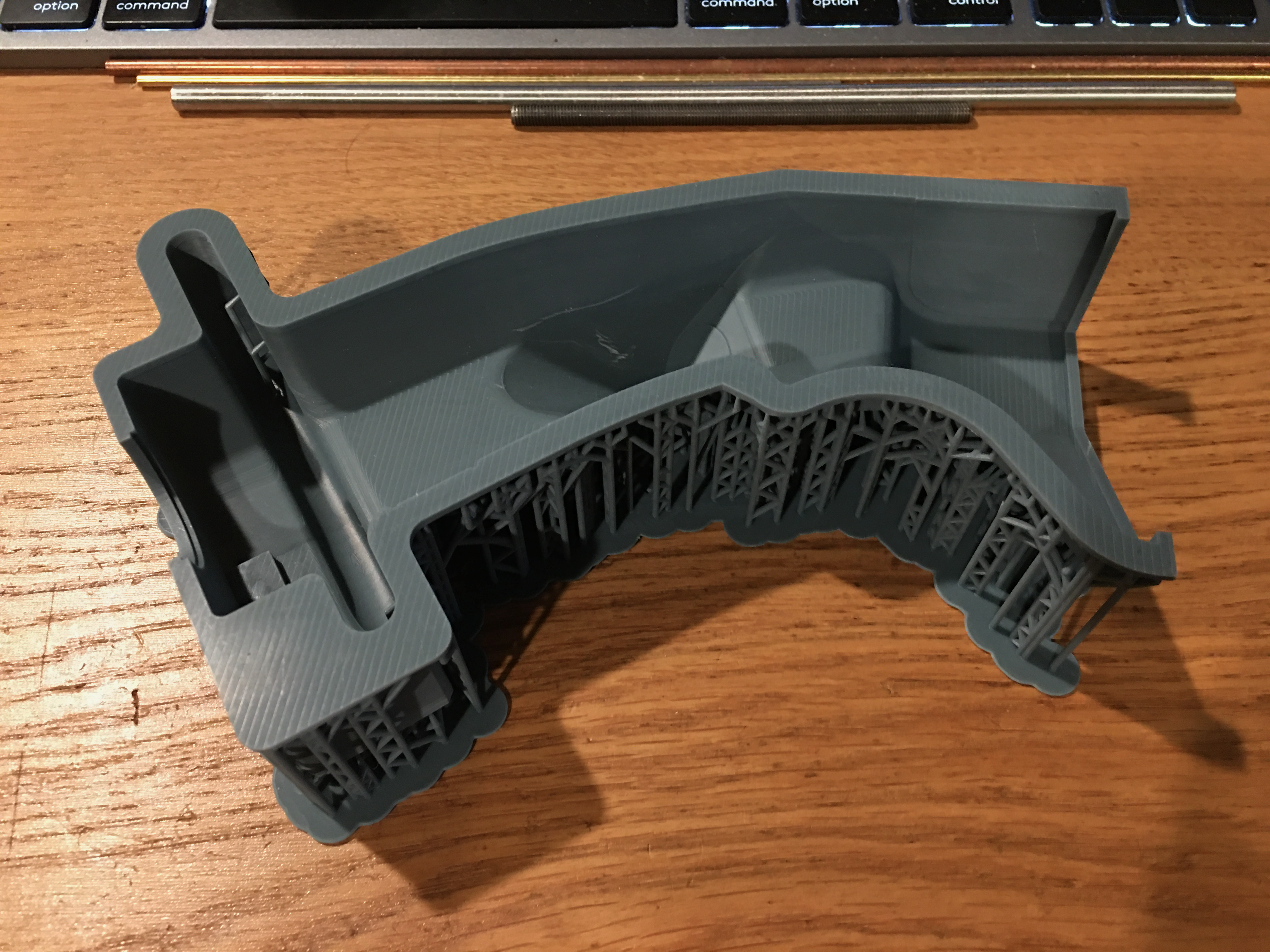
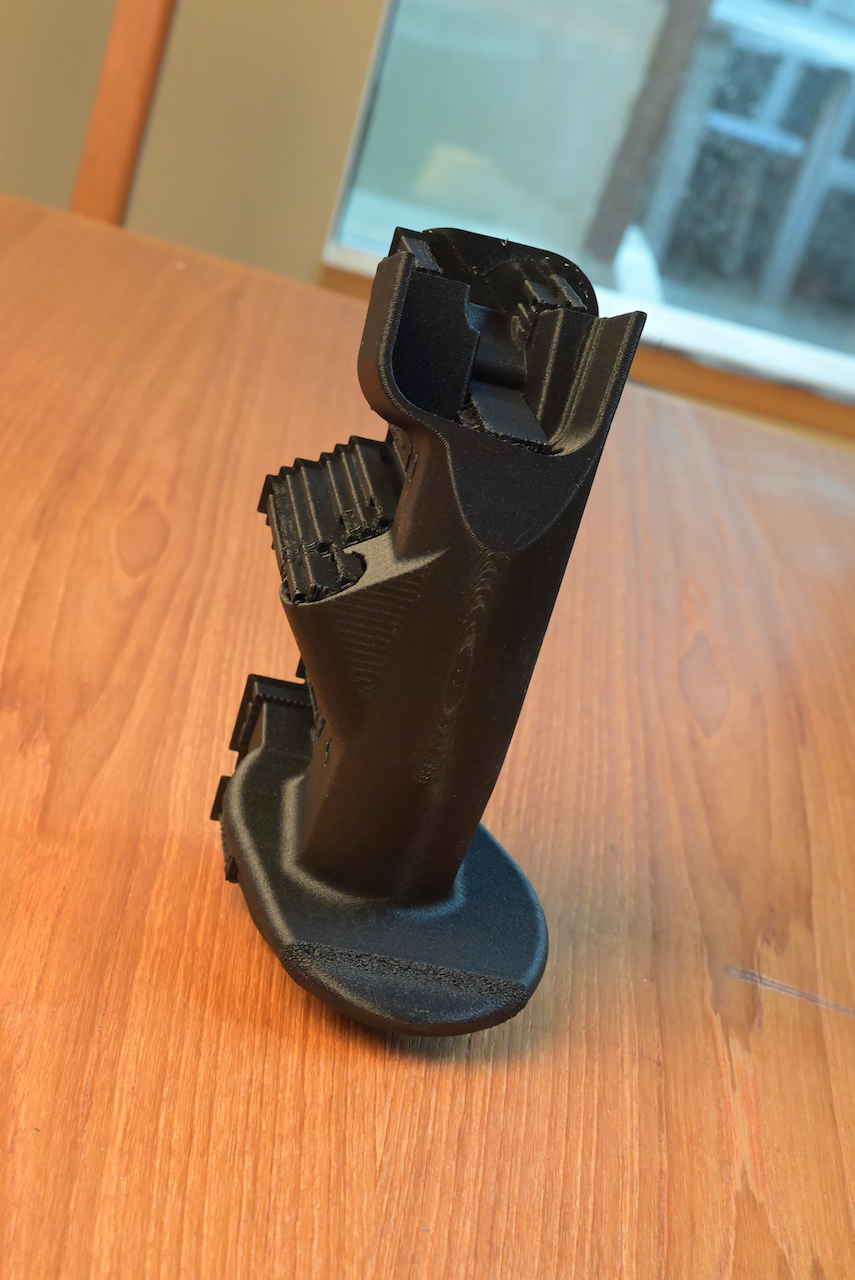
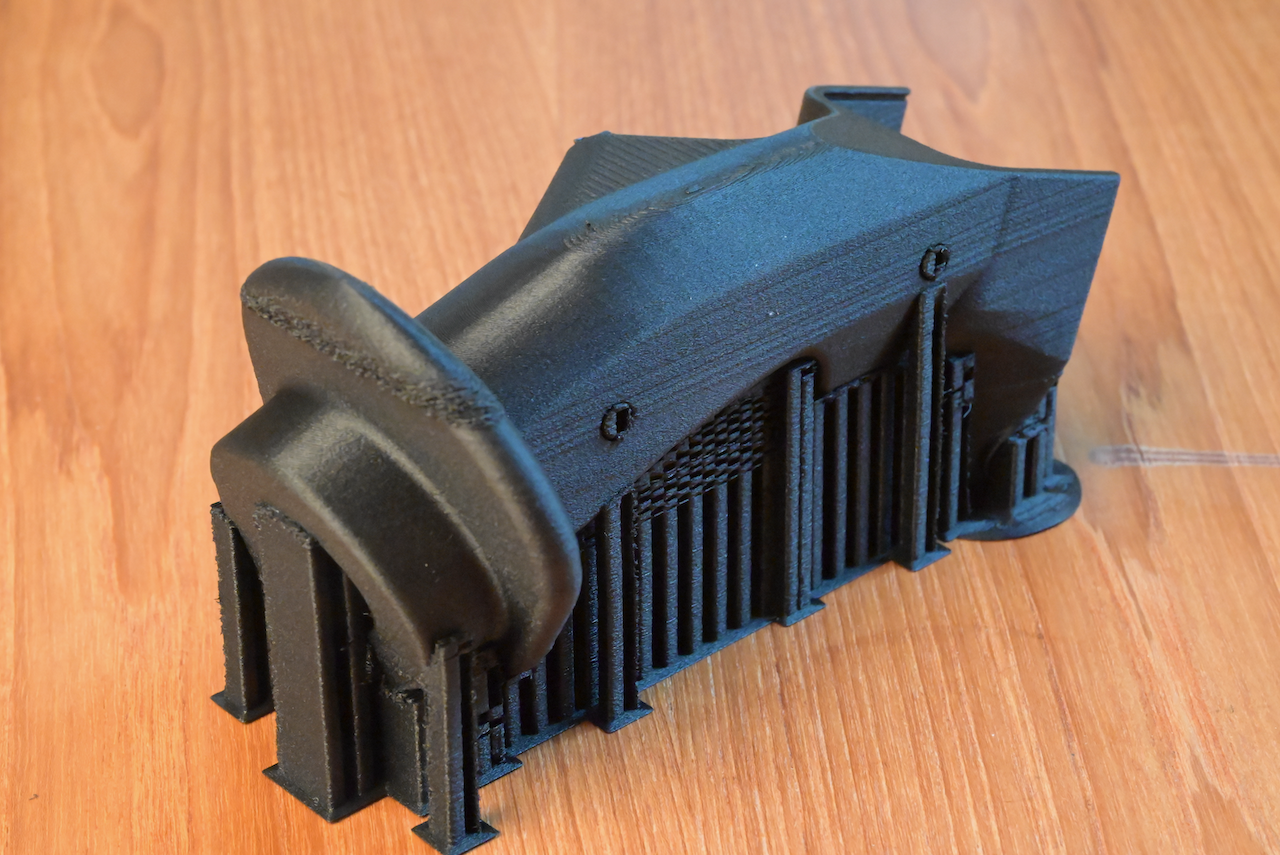
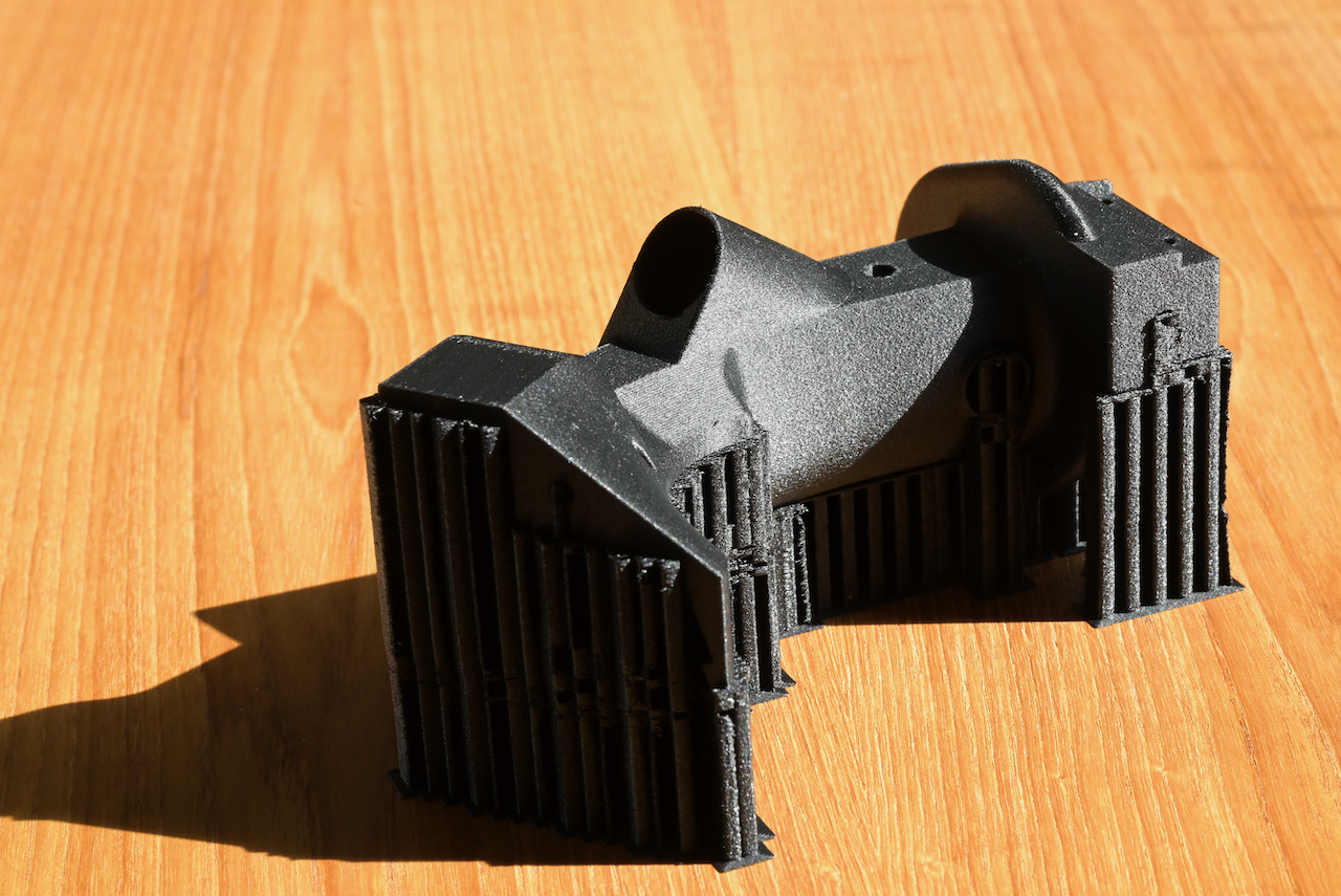
100% infill Nylon 12 Carbon Fiber. Fresh off the printer, support tore off... no sanding yet. I am pleasantly surprised about the raw surface texture where the support touches main body... not bad... a little sanding would take care of that. This is extremely strong! Also, take note on the back of the handle where the main body bends... This is the top of a curved 2-directional curved surface, printed horizontally. Usually, with fixed layer thickness, 0.2mm, you will get a serious stair case isolines. I turned on the adaptive layer height printing, so those staircase lines are dramatically reduced together with drastically increased print time. But, I think this is worth it. It will make sanding a lot easier. But, like I said in the previous post... it took about 12 hrs to print it.

-
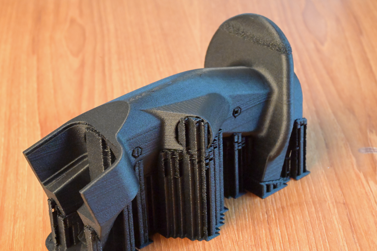
100% infill, speed adjusted for strength... adaptive layer heights, rotated to have the trigger part facing down for support... all the trimmings... It will take about 2x amount of filaments, 103g vs 207g. And it will take 11 hrs 50m vs. 4 hrs 49m. It's being printed, now.
-
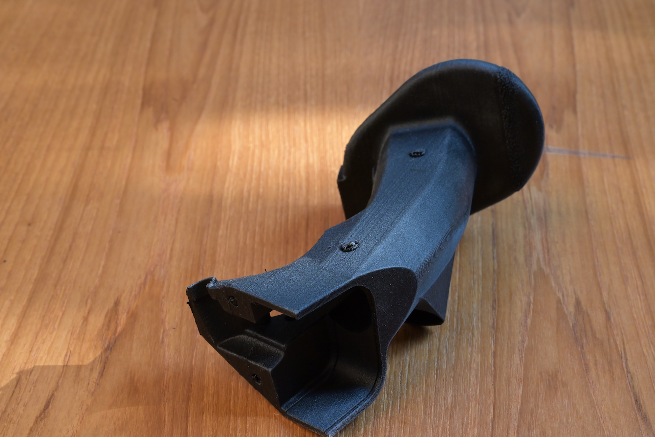
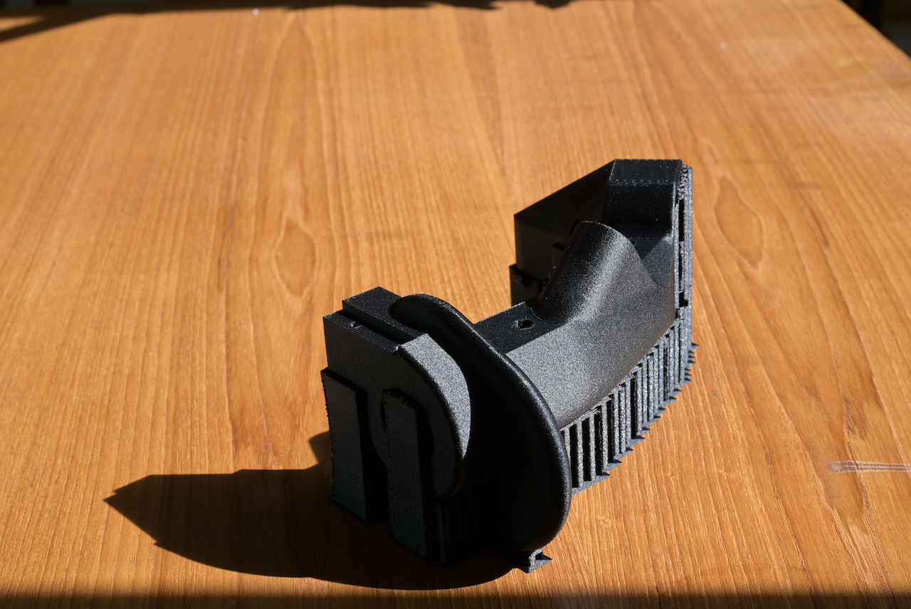
Nylon 12 Carbon Fiber printed (damn, I forgot to get rid of the screw holes designed for fastening two halves!). The surface condition on the supported side doesn't look too bad, nothing a bit sanding couldn't solve. There are some surface defects on the top side as well... nothing a little epoxy potty and sanding couldn't solve. It's incredibly light (feels cheap), but strong. Next time, I will try printing it with 100% infill (and get rid of the unneeded screw holes). Now I just have to figure out how to get the support materials out of the core. Don't need to have perfect surface condition inside... so shouldn't be a problem. Next time, I might print it with the trigger side down. This way, the surfaces we see mostly have better surface condition.
-
Try the drop down "Show all Axis Command", and then see what else axes are bound to Roll/Pitch/Yaw and Throttle. Clear them all except the ones you want! DCS has a nasty habit of "autoidiotically" assigning any analog axis of all "new" controllers it sees to Roll/Pitch/Yaw/Throttle in a "common sense" fashion... all of them! Make sure you have one and only one axis of one controller bound to one of R/P/Y/T. Any time you plug in a brand new controller/mouse DCS has never seen before, it will again autoidiotically assign the new axes again... to all airrcrafts you have! So, any USB device reporting analog X/Y/Z/Rx/Ry/Rz axes will autoidiotically be assigned to R/P/Y/T, respectively, all of them! So, you bump your desk, and the idling mouse would suddenly try to assert its authority over your roll and pitch. But from your PoV... you have no idea where that "unintended" movement came from! It might win some and lose some against your TM Warthog. Or, you pull on the TM stick hard, and some yaw authority would come from nowhere and then quickly evolve into an uncontrolled nose dive. Any combination is possible. All kinds of weird things could happen!
-
The new Bambu X1 Carbon prints so much faster, but it's actually not as fast as the eye can see. The real comparison is that after slicing and actually printing one half of the thin stick mold... it's about 14hrs vs 8 and 1/2 hrs (Ultimaker 3 vs Bambu X1 Carbon). The thing about it is that both are core-XY mechanism. The Bambu print head moves and prints at eye blurring velocity, while Ultimaker 3 moves a strolling pace. I would have thought that it moves at least 3 times faster, resulting in 1/3 print time. But no. It's a tremendous time saving, but not the 2x 3x time faster as I was hoping for. 40% time saving is nothing to be sneered at, but it's not 66% or more! (My Phrozen Might 8K prints the same thing in about 4hrs!) My guess/observation is that Ultimaker 3 has dual print heads, 1 prints with the primary filament, the other breakaway support. For each layer, switching filament is quite fast.... basically heat up the idle print head which is already almost up to temp... a second or two, then go the prime tower to print a round or two... and start printing. On the other hand, X1 Carbon has one print head only and an Automatic (filament) Management System, which would retract the current filament, it would need to readjust the temp of the print head for different filament, heating up would need the similar amount of time as U3, but if it's lowering temp... that could take longer. Once the print head is "up" to the temp, it has to re-insert the other filament by feeding it all the way from the AMS to the print head, then slowly feed forward to eject enough into the purge chute (similar to your loading filament operation), clean up the print head, then start printing (starting with the prime tower). It has to do this twice for every layer that has both primary and support portions. That adds a lot of time. I have already did the sensible setting of only using support filament on the "support interface" instead of all support. Meaning... only a thin layer of the support will be printed with support filament... so for layers that do not have support interface (the few layers where support actually connects to the primary article) do not need to go through this time consuming unloading and loading filament operation for each layer. I do expect that if you use the same filament for primary article and also for support... the print speed would dramatically improve. But I do not like that, as for some of my more complicated designs, it's very difficult, if possible at all, to break the support off! In essence, X1C is much faster than U3. But not the 2x 3x faster you might expect in practice. Durability, reliability... don't know for X1C yet. But U3... it's been utterly reliable for me in the past 5 years. But, since Ultimaker is also a coreXY machine, i.e. both movement of X and Y axes are on the print head, its head design is also light although not as light as X1C. It potentially can move faster than it is now if Ultimaker also program in Input Shaping as Bambu does. So, U3 speed could improve, but with Ultimaker's current "corporate direction", I am not holding my breath. In reality... I will be using the X1C as more of my exploratory printer (if it holds up to my abuses), and U3 as the primary.... and the fleet of resin printers as the messy-only-when-print-quality-matters stuff, like the knobs in the pit. Or... printing plugs for silicone RTV molding (lost wax).
-
Bought a Bambu X1 Carbon, upper left in the picture of my 3D printing "nook." Not shown in the picture is my messy vacuum pump, pot, and hoses on the floor! Boy, is this X1 Carbon fast! Don't get me wrong. I love my Ultimaker 3. It's my go-to printer, despite my plenty of other "choices." Slice it, send the file over, as long as the damned auto-leveling passes, it will print and get me what I want.... just slow... but very reliable. What I have problem with.... is Ultimaker's direction -- enterprise-oriented direction. New Hardware has very little innovation, and charge an arm and a leg.... and worst of all, no upgrade path for faithful customers like me. No Ruby print head and abrasive filament resistant parts that are in the S3 and S5 but no upgrade path for me, and charge like USD $4,500+ for a new S3! So, I can't print carbon fiber with my Ultimaker 3..... ya ya ya... I can try to mod it and stuff... but thank you but no thanks for messing with my primary printer! So, I have ordered some PETG CF (Carbon Fiber) from Bambu... maybe that will be good enough (I doubt it!, but I got to give it a try, right? And, I am sticking to it as my "justification" for buying the X1 Carbon!).
-
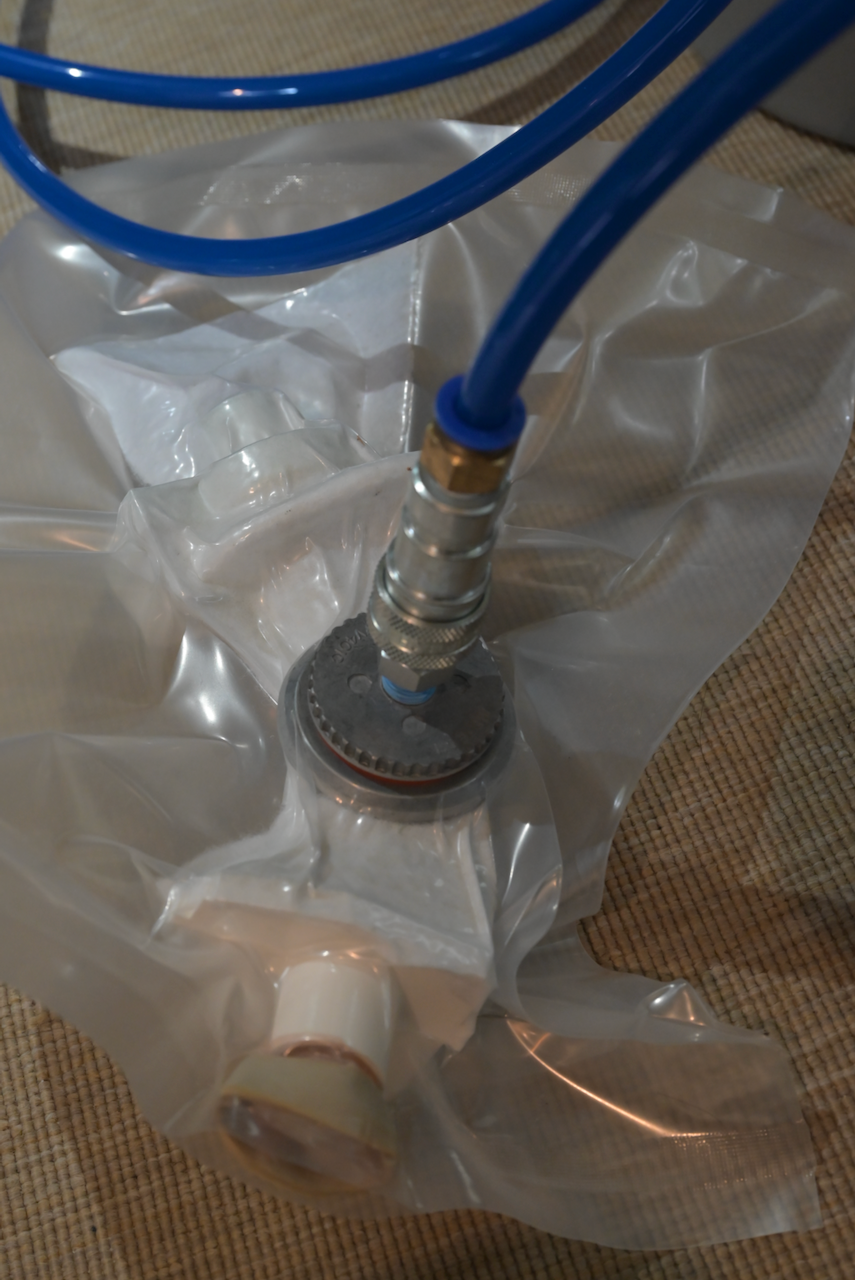
I was finally able to make the experiment today using the borescope and a new my own design of wrench for bicycle Shrader valve with the Stretchlon 800 plastic sheet. The idea was to rely on Stretchlon 800's ability to stretch and vacuum pressure to have it stretch and compress the fiber/resin mix from inside without the "ugly" folds of plastic bags. The folds could sometimes cause resin blocks locked inside making extraction difficult and require a lot of post processing. The experiment result is that the vacuum pressure I was able to achieve with a vacuum pump purchased from Easy Composite in UK, it wasn't able to stretch that much as I hoped. I was hoping the stretching to be the main "shape conforming" component but with excess material folds to supplement it. Unfortunately, the experiment result shows that I will have to live with excess material folds to be the main component, with stretch of Stretchlon 800 as supplement. In other words, I will just have to make the diameter of the inner plastic tube big enough to minimize the stretching, instead of making the D as small as possible but rely on the Stretchlon to expand. I guess, next experiment is in order -- paint on silicon RTV as the inner "bag." That, for sure, will have no fold.... but it requires making a new inner plug (extra CAD and 3D printing time).... Oh well...
-
Ya... tried just casting it. that was the original original idea... hot hot hot... Hence the thin shell idea of about 1mm thick, maybe 2mm max (would prefer to keep it at 1mm or thinner if I could). Tried using woven sleeves (D=4.5")... difficult to get it to conform to the more extruded parts of the plug...(the palm rest, obviously cannot be done in 1 piece with woven sleeves). Plus, it's going to be difficult for later more shapely control sticks/throttles like AH64, F15, etc. In other words, I am searching for construction methods that is as generic as possible, yet easy to do at home. Hence, the one time disposable thin mold (commercially bad idea as it took about 30 hrs on an FDM machine, 4 on an SLA, instead of the lost wax process for metal casting, over hang all your want within reason, and no daft angle required, no need to split the mold correctly), and thin shell. With chopped tow... the more shapely curvatures necessitate compression (even the woven sleeve requires compression to hold it to the desired shape), -- either use two, or three, rigid mold halves to compress it (draft angle again), or... do vacuum bagging. Vacuum bagging is far more flexible than rigid molds. I am sure open lay up of two halves and then later glue or bolt together would be good enough for commercial efforts... but I am not looking for commercial venues. I am just looking for a better way of doing it at home. If you have ever tried the Solidworks mold tools.... trying to split the damned F16 throttle mold, you would know how difficult it is to use SW to split that mold... Oh man... took me two weeks of trial and error to find the "right" lines to split it off into several pieces. It will tell you you don't have enough draft angle here, there... there is always something that got in the way no matter how I split it... until I cut it into more than 2 pieces.... It was neigh impossible to do it in two-pieces casting... for wax mold. And since it's going to be a bunch of flexible hand made silicon RTV molds, SW's mold tools was just too "rigid." It was obviously designed for CNC milled solid metal molds. Even a simple F16 rudder pedals are difficult to split due to those little ridge bumps on the side of the pedals. It's just difficult.... if you are doing mass production, it may be worth the efforts to go through that... but one off, two off... it's just not worth it. Hence, I tend to like lost wax... you are free to design it in any shape you like.... no need to consider later construction methods and change the designed shapes to fit that construction methods... much.
-
Simple. I want the outside dimension to be exactly how I designed it. There are basically two ways of doing composites. 1. You make a core, then you do a “lose” lay up. That is, you lay up the fiber on top of the core and dabble the resin on top of the fiber. 2. you do something to compress the fiber/resin to to the form so you a. squeeze out the air pocket and b. you make fiber/resin more compact, which reduces the resin/fiber ratio. You want the resin to fully fill among the fiber, but no more. The more resin you have after that does not contribute to structural strength. Moreover, the more compacted the fiber, the stronger the structure. Vacuum bagging is commonly used in composite construction, particularly in experimental aircrafts. It’s easy to do, and cheap, produces even compression, and can easily be done in garages. Now, since I want outside dimension to be exactly as I designed, #1 approach is out. I could do forged carbon fiber by printing two half of molds and compressed. But, with the stick shape, I might need 4 pieces mold, and will require daft angles to be design in! I need outside mold, yet I don’t like outside mold. Plus, how do I form the inside shape? So, the original idea was to print the outside mold, 2 pieces, the place a structural aluminum tube inside and cast. Two troubles. 1. The epoxy volume is too thick… exothermal reaction, gets it too hot. 2. Compression is a bit difficult to achieve. And how do I get that thing out. I actually destroyed the mold trying to get it out. So, change of plan. How about just cast a thin carbon shell, with a thin disposable mold? Then destroy the mold to get it out is easier and takes less time to print. Then I can use other material to cast in the structural tube and form the inner shape. Say, high density expansion foam. The problem? I need to compress the thin layer of fiber and resin mix in order to get the thin shell. But, then if I use a ballon to blow up from inside, the thin mold would easily be distorted. I could cast some plaster outside of the thin mold to reenforce. Or I could CNC the mold out of two pieces of big chunks of aluminum. But, vacuum bagging will allow me to compress from both inside out, and also from outside in simultaneously so not to distort the thin mold!
-
Just came back from Asia last weekend... This weekend... dry test for Strechlon 800. Not sure if it worked... The whole idea is to see if Stretchlon 800 can strech up to compress all corners. Seems to when I peeked from one end (D=1"), but I couldn't see all the corners. But, once I cut it open... not sure if it did (might have been it did, but once the vacuum is removed, it sprung back???). The result is inconclusive. I mean, should I make the Stretchlon tube's diameter bigger? How big? Why Stretchlon? I could use an oversize plastic tube... like everybody else does. But doing this has the trouble of some "folds" of the plastic bag would lock in some excess resin causing undesired bumps and ribs. So, if Stetchlon can "stretch" up to all corners, then there should be no locked bumps and ribs of resin, b/c there will be no folds. The alternative is to use a kind of paint on silicon RTV to make a silicon inner sleeve so it's exactly the shape of the cavity, hence no fold whatsoever. Then use this inner sleeve for vacuum bagging. I am trying to avoid this approach, b/c it's more expensive tooling and processes, although I have already ordered and received the said paint on silicon RTV (it's expensive! And think printing a different mold for the silicon sleeve, mixing the resin, degassing... paint.. and correct the fit, etc. etc.). So, if I can avoid another whole different process, and use only regular vacuum bagging with plastic bags, albeit different plastic bags, the better. So, I ordered a bore scope . Now back to waiting for delivery. null
-
*imitates Nixon's voice * It ain't if I do it!
-
I guess I will keep trying to contribute to the compounded server load. Is there a script to automate this?
-
1. It ain't a SPI bus (although it's possible to drive it with a SPI module). 2. It is supposed to be a daisy-chain of 3x cascaded CD4021 chips, i.e. 24bits. 3. The firmware to read it... it will assume #2, and read 24bits. So, if you only have one chip, the firmware is supposed to "still" read 24bits off the chip. So, it depends on how you wire up pin 11 Serial In. Assuming you wire up the chip correctly, and the firmware is reading correctly, then, if you float pin 11, you most likely will get the correct answer for the first 8 bits, and 8th (0-index) bit and beyond are pure garbage. If you ground pin 11, as you are supposed to, then you get 0s from the 8th bit and up. If you wire it up to Vcc, then you get 1s from the 8th bit and up. Read, pp. 34 to 38 of Hempstick User's Guide, https://www.hempstick.org/download/manual/Hempstick-UserGuide.pdf, for the correct pin assignments.
-
Wanna bet whether A P P L E will focus on health craze like with the watch? It seems to be their corporate crowd.
-
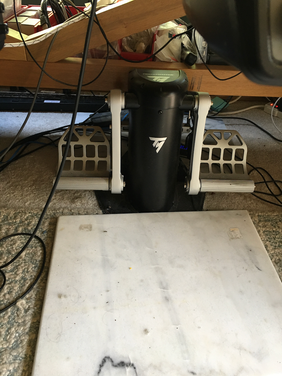
nullMine is bookended by two marble plates. Don't buy them from kitchen supplies stores like I did... very expensive. Anyway... I used other methods like a long stainless steel rod to butt against two front legs of the table. But this 2x marble plates method is much better. 1. I get to position it anywhere I like, instead of where the table legs are. 2. The rear plate serves as a glide surface for my heels without wearing two tracks on my carpet, like most planes and cars do. Plus, the marble surface has just the right surface roughness for bare feet to glide on. Bottom line is... just some plates heavy enough, with the surface texture you like.
-
Oh... BTW... forgot to mention... this "disposable" mold is an experimental concept.... The idea is that this serves 3 purposes. 1. It's an experimental step to tease out the carbon fiber/epoxy molding techniques and design details, for instance the first molding kinda-success/kinda-failure led me to the two caps. 2. It doubles as an one-off manufacturing process most of do. I mean, 30 hours printing for a mold that you can only use once is definitely not for production. But it serves most home projects well... particularly it frees us from the worries about over hangs, draft angles etc. etc. Very liberating for design and manufacturing process. 3. Once #1 and #2 are completed.... I might consider using the one-off mold to make another mold for using high-density expansion foam to make the one-off mold (as well as using it as filler between the thin carbon fiber outer shell and the internal structural tube (or just the thin shell!). I may or may not go to step #3... But, it's been in the back of my mind during the design process. Just found out... I have always used Smooth-On X3D 3D print epoxy to smooth out the FDM mold etc..... to great successes.... I just found out... it's a completely redundant step to do in this particular process.... in fact, it's down right detrimental. Don't do it! Lesson learned.
-
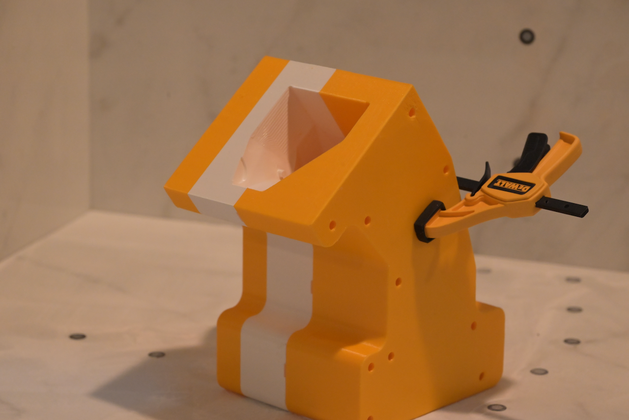
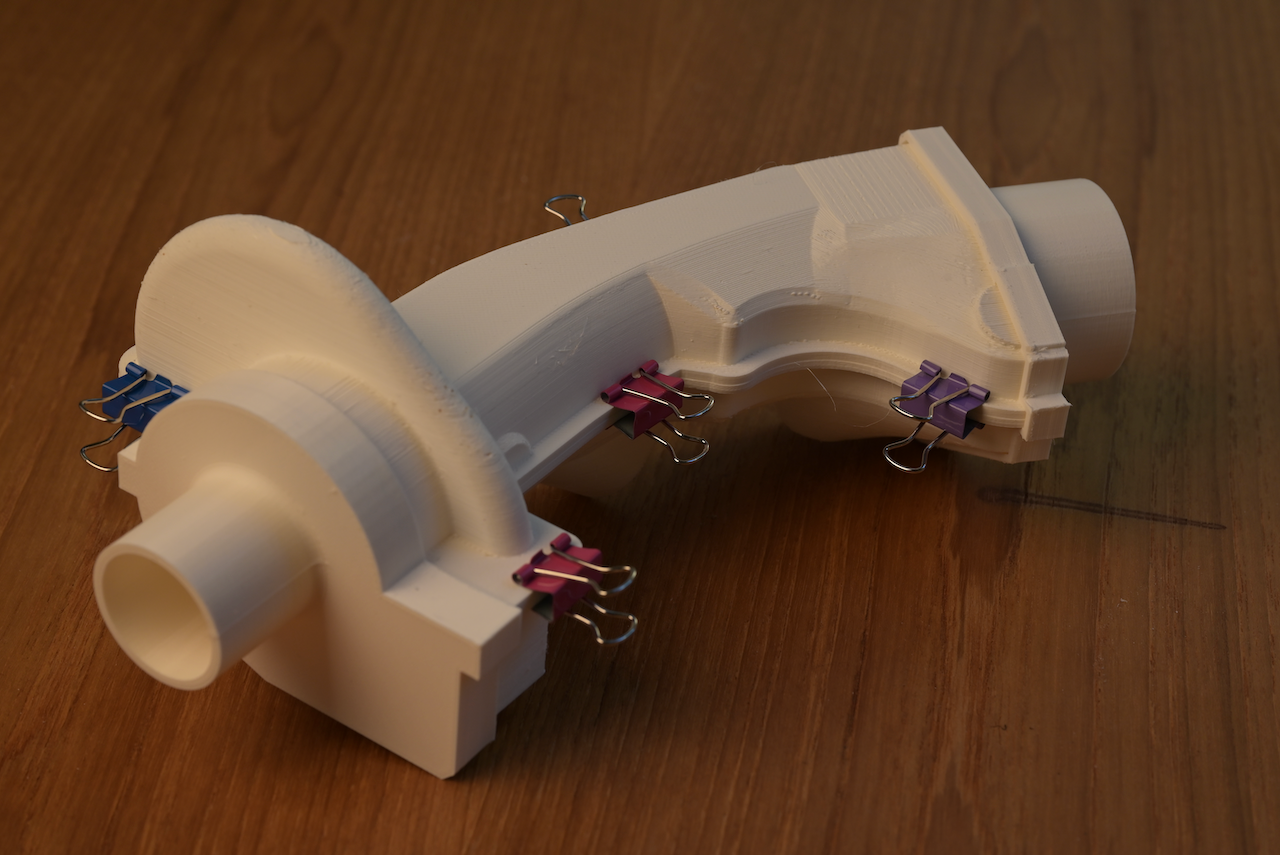
The two mold end caps. They serve for two purposes. 1. to clamp and align the two mold halves, not for "capping" the resin/carbon fiber mix. The mold is only for outer shell molding using vacuum to compress fiber/epoxy to the outer shell... the two ends... no. But 2. to create a space and shape to prevent the outer bag from getting sucked into the middle and pushes the fiber/epoxy mix inward and causing some parts of the article starve of fiber/epoxy mix. Hence the two tubes on each end. They are there to create the extra space for the outer bag to get sucked in without reaching the fiber/epoxy mix. Also, they are there for the inner film tube to anchor and seal with the outer bag. In the end, I might forgo the metal clips and just use some twine to tie up the two halves. I mean, all I needed is a temporary tie until the atmo compresses down. What I need is more of alignment than pressure down. I am hoping the two end caps are reusable. We shall see.
-
null All printed. Still needs some end "caps" to prevent vacuum bags to be sucked in and distort the tow/epoxy mix. White one is PLA filament. The gray one is Phrozen 8K resin (not that it matters).
-
null
-
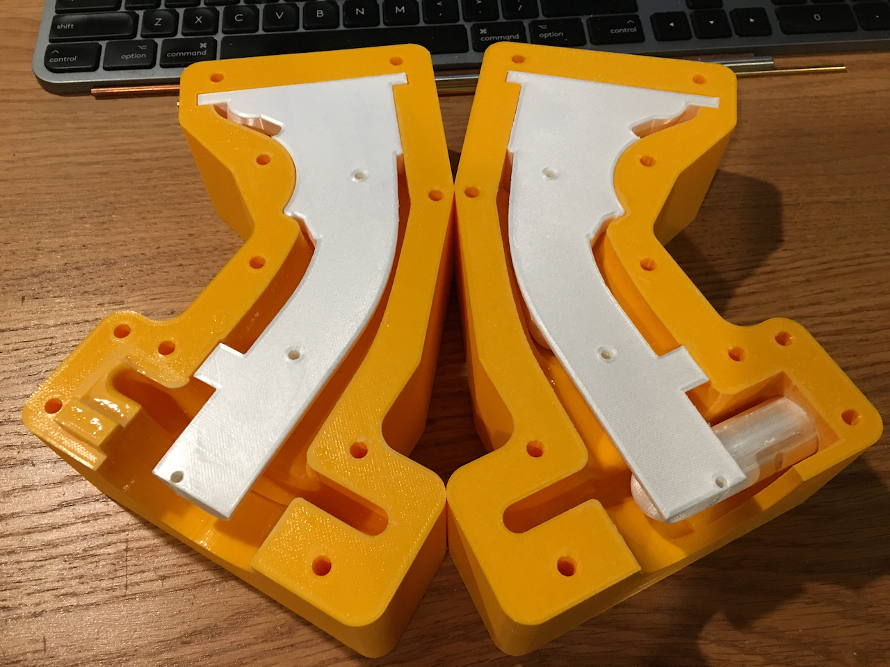
Thin shell disposable mold (half), printed on my Phrozen Sonic Mighty 8K... fits just barely in the Mighty 8K so I don't have to pull out my Mega 8K printer. I hate using the Mega 8K... just think how big your ISO alcohol tank has to be, and how man gallons of alcohol you gonna need to fill it! Using an 8K printer is overkill. a 4K or even 2K printer would do just fine, resolution wise. B/C, no matter what you do, this thing has to be heavily sanded multiple times. However, my Sonic Mighty 4K is just not big enough. Whatever, 8K it is.... It took about 3 hrs 48 minutes to print.... the same one being printed on my Ultimaker 3 filament printer will take total of estimated 13 hrs 50 minutes.
-
nullBeginning of 1mm shell mold. Still need to add reinforcement ribs, and some extensions to help prevent the unintended vacuum compression of both ends. I might consider using 1 of my 4 SLA printers for it for two reasons. 1. SLA prints hell faster than filament printers. 2. It's a disposable mold... SLA prints from the generic resin is fragile... but maybe it's strong enough for one casting. If so, then it's fragility might be an asset for de-molding, i.e. destroy the mold. I might have to worry about SLA resin inhibits curing of epoxy... A lot of PLA release film and/or wax perhaps? null null
-
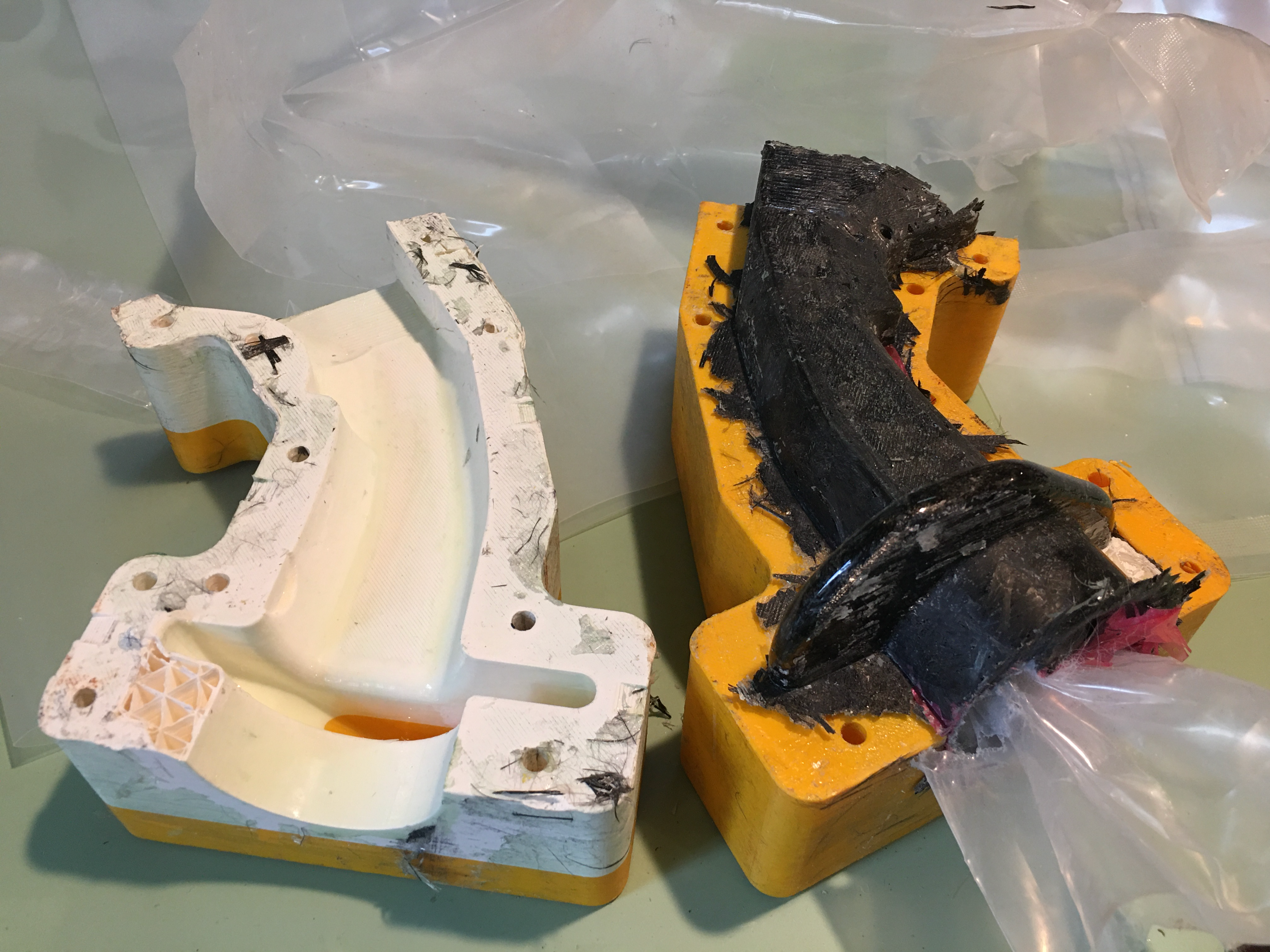
Kind of works. There are some "forging" defects. So, next forging will correct that. However, the biggest problem is there is pretty much no drafting angles... so it's very difficult to extract it from the mold. I pretty much destroyed the mold (20 hrs printing each half). I might be able to cast one more out of it... but... that's not good. So, now the idea is... how about just offset the shell out, say 1mm or 2mm, and add some reinforcement ribs... that's the "disposable" one-time use mold! After casting/forging, just destroy the mold! Doh! Also, as you can see, the seam has some red release film got pinched.... these are some casting skillz I have to learn and perfect, etc. etc. But, in general, the carbon fiber prototype is heading toward the right direction. I might even consider printing a mold for casting the disposable mold with high density foam (quite difficult to buy very high density ones, it's a 16 lbs density 2-parts expansion foam that can give you a lot of details and a lot of strength). nullnull
-

cannot repoduce and missing track file AGM-65D not locking?
Hempstead replied to tflash's topic in Bugs and Problems
-
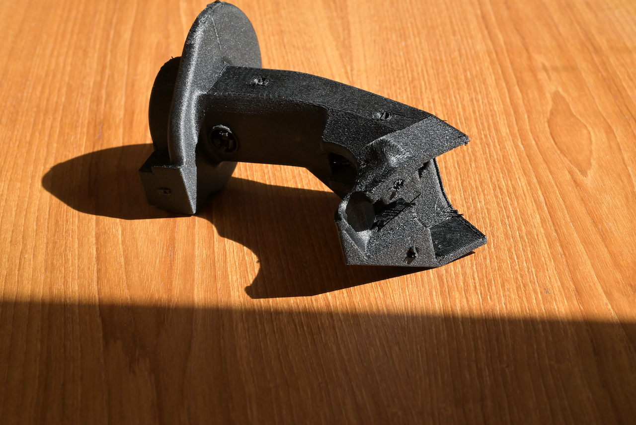
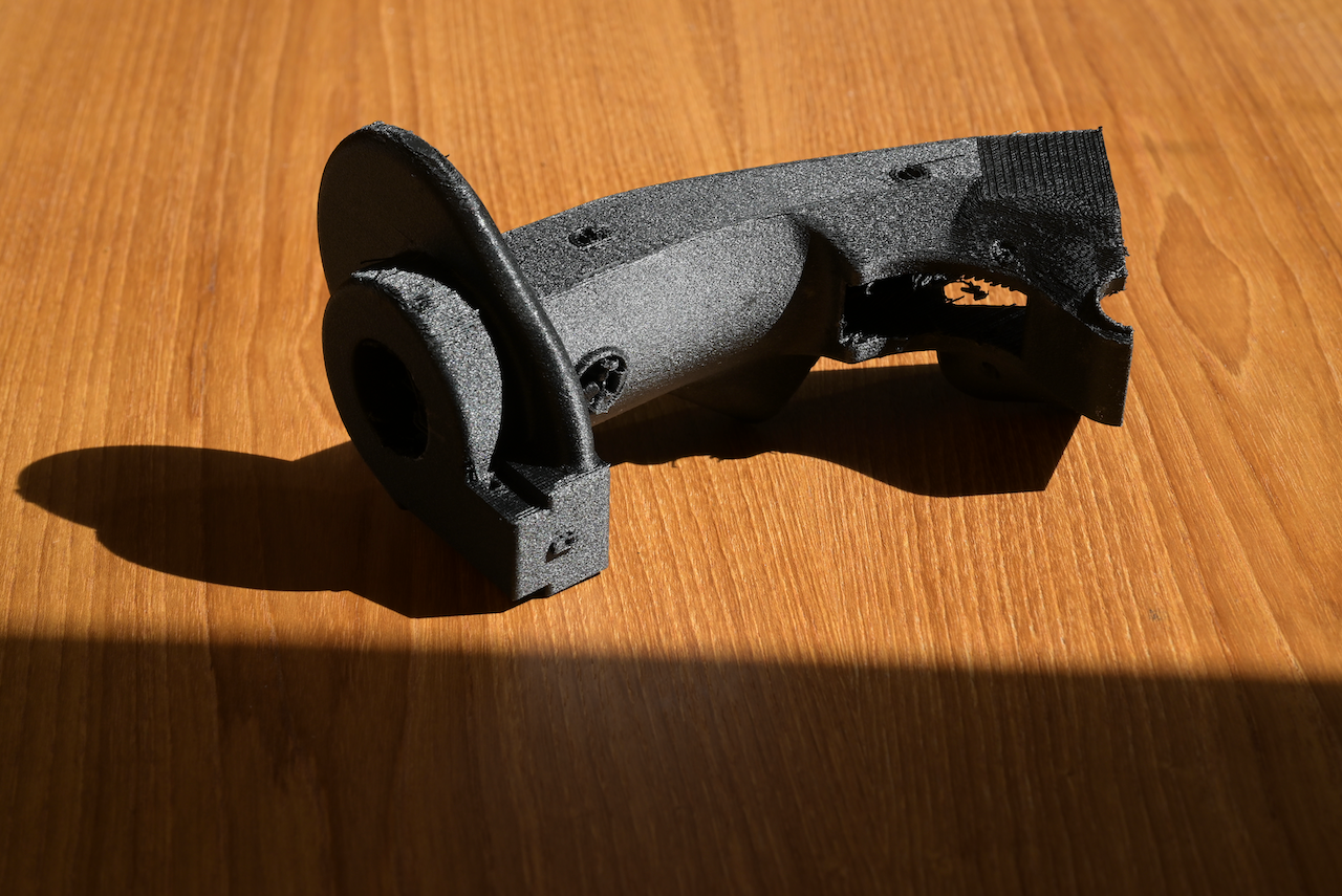
I am changing the mold and construction method. The basic idea of forged carbon fiber with a Breakaway core construction is sound... but there are technical difficulties. The most important part is that there is various thickness on the shell, vastly different thickness; some parts are over 10mm thick, some barely 1mm thick. It's very difficult to get the right amount of Carbon Fiber tow at the right place and have even compression. So, it hit me... why don't I just keep the mold and do a thin even thickness Carbon Fiber tow shell on the mold... and vacuum bag it to create a compression force? The rest of the cavity... I can either pour in cheaper glass fiber epoxy mix or, hell, high density expansion foam. So, I am changing the construction method. I am going to use a thin shell forge carbon fiber construction method. I am sure somebody else invented it before I came up with it. Basically, I am going to put a thin shell of Carbon Fiber Epoxy mix on the two halves, just like in hand lay up. Close the two halves... put in the release film, absorbent fabric, and a plastic tube in the middle and close the two halves. Then, I will vacuum bag it. This will give me a thin shell of "forged carbon fiber" look. Then, I can put in the Breakaway core and "pour"/tamp whatever space left between the core and the shell. Perhaps I will even use a very dense expansion foam I have at hand (16 lb... your regular structure foam is about 2lb.). If I use the expansion foam... then, the Breakaway part would only be the "head" space. The tube part could just be a carbon fiber tube and have it embedded right in there. That is, if the 16lb expansion foam is structurally strong enough (it should... I guess...). Therefore, I chopped up the mold to facilitate the thin shell construction. Like I said many times before in other places... my F16 3D models are just models.. they are not design. This here is the design/construction process you have to go through after the 3D model was constructed... many times.
-
I decided to leave the bottom open... this way, once the two halves of mold are closed, I can pour in more epoxy/carbon fiber mixture from the bottom and use a cylinder to apply pressure.


.png.cc2679b2dbd1ee063dc73e2991fc8e21.png)