Frederf
-
Posts
7593 -
Joined
-
Last visited
-
Days Won
3
Content Type
Profiles
Forums
Events
Everything posted by Frederf
-
Commonly Dan Hampton quotes describe stuff which is not textbook F-16 terminology. I think he is loose with what things are called or he's using something exotic/old. I've never heard of a "HARM cross". A slapshot HARM sounds like HAS (LOBL) or a POS RUK (LOAL). Probably GW is 88B block 3 and no HTS, right? 83 A blk 1 86 blk 2 eeprom 87 B spans blk 2 and 3 90 wgu2b which allowed blk 3 for flex & PB 93 C with wgu2c and blk4 Next update was called blk 5 or 3a depending if applied to a blk4 or 3 respectively. The Navy waited for 3a (staying 2) because they avoided 3 as programming the missile required powering the missile on CV, danger. By 2007 USAF is certainly operating 88C blk 5. D model operational test was scheduled for late 06 and IOC 08. Technically RUK should turn toward steerpoint but if it starts homing quickly after launch then I suppose it can be used on any bearing as effectively a straight shot.
-
I don't know of any specific feature for that like providing AFAC lasing. It will do a long duration rangefinder during some CCIP/strafe type attacks plus there is auto lase for laser weapons.
-

correct as is F-16 MFD brightness dims selecting each menu
Frederf replied to ac5's topic in Bugs and Problems
The text pages all share a single setting. The video pages each have their own setting set. There is a day bundle and a night bundle saved in the pilot's DTC preferences. He wouldn't have to set them in the airplane normally as they would normally load with the DTE file when starting the airplane. Text formats: SMS, DTE, TEST, FLCS, HSD, blank Video formats: FCR, WPN, TGP, FLIR, RCCE The particular format intensities do not change between master modes. E.g. if you dim SMS in NAV then SMS is dim in AG. If you dim FCR in MO then it's dim in NAV. You're only seeing brightness changes because different formats are present in the different modes. If you have a track showing different intensities for the same format simply by a mode change then that would be good to see. I could not cause that behavior. -
correct as is F-16 MFD brightness dims selecting each menu
Frederf replied to ac5's topic in Bugs and Problems
I don't understand. The MFDs do not automatically dim as that is not a feature of the airplane. However each MFD responds to the adjustment rockers regardless of the time of day. What behavior do you expect and what behavior is the DCS airplane not having? -
You can of course use the ILS localizer and glideslope plainly without the synthetic runway and other features by simply tuning the ILS station and looking at the position bars on the ADI. The marker beacon receiver would work as well. If that's the level of service needed then that's all you need to do. Only for the additional layer of the synthetic runway and steering cue features is more information required. The system needs data which is uses from whatever BUT (waypoint) is selected. Also the full system requires that QFE barometric altimeter setting is used for accurate display. The important digital data is the runway geographic heading, ideally to the 0.1° and the angle of the GS (3.0° in all cases). The system uses this extra information to provide display and guidance relative to the ILS beam to provide those extra features.
-
TMS right (short) only steps between system tracks. By default all tracks are tank tracks (not system). To be steppable/snappable they have to be elevated. Elevation can happen by cursor and TMS up (no bug) or if there are zero system tracks by TMS right (elevates up to 10). Un-elevation is by TMS down (no bug). It's really hard to tell what's going on with the Link 16 layer on top which is why it's a good idea to learn how it work with MIDS switched off. Here's a track showing manipulations of the TWS radar and elevating/un-elevating/stepping tracks by TMS up/right/down. F16 TWS step.trk
-
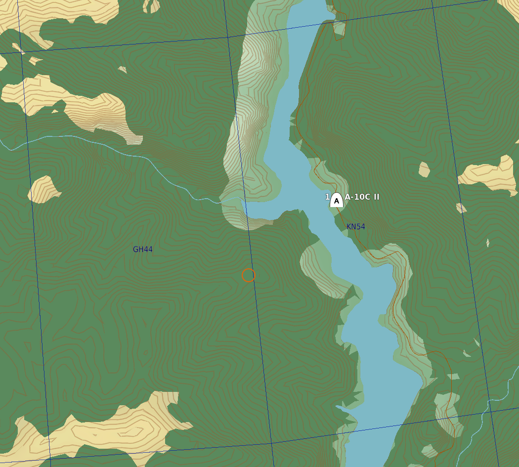
They mean 38T KN545441. 37TKN54 would be way way off the normal 37T UTM into 38T again. A lot of people forget the UTM which is a necessary part of a complete MGRS location. KN54 is right on the 37T 38T boundary. In fact the KN545441 location is on the wrong side of the UTM boundary. It's in one of those weird overlap MGRS zones which spill across the UTM boundary where two MGRS addresses can refer to the same plot of land. The A-10 will accept either of the double-addressed locations although the correct one is preferred for accuracy. Converting the six-digit grid into LL and back into MGRS it is correctly expressed as: 38T KN545 441 -> 42.8100936°, 041.9973767° -> 37T GH 450 440 That's approximate because I truncated. Be aware that MGRS always refers to the middle (or entirety) of the square addressed of any size, not any of its corners. I.e. KN54 is not the same as KN5000040000. KN54 is effectively KN5555545555 but with an infinite number of 5s. The A-10 (at least in DCS) however will just add zeroes and thus takes the corner when increasing the precision to 10 digit. So watch out as that's an error of ~7.2km for a 10km grid. A lot of people don't pay attention to the center-of-square rule as well. KN545441 is a perfectly valid MGRS (as is KN, KN54, KN5444, KN541441, KN54124412, KN5412344123) and 2-4-6-8-10 digits can all be entered into the A-10 CDU just fine. The letter-only zero-digit (100km grid) entry is rejected.

-
Here's an example mission to practice on and a track demonstrating. Procedure Active pause ON INS Preparation: INS parameter dL/dG 1or7 N 11118 INS 3or9 E 14024 INS INS parameter dALT 3or9 + 95 INS Weapon Preparation: BL1 select PI select NB 08 DIST. 02 Fuze INST Weapon command FWD Active pause OFF INS update: Fly radar diamond to reference landmark (control tower) Press Magic slave button on throttle Attack: Follow navigation cues to align with target Master ARM At toss range select afterburner and pull into loft while maintaining lateral aim Hold trigger before solution is reached Train M2K M82 PI.miz M2K PI Attack.trk
-
correct as is F-16 MFD brightness dims selecting each menu
Frederf replied to ac5's topic in Bugs and Problems
At 33E/45N 2000m on 21 June 2016 According to A-10CII and F/A-18 and F-16: 20:59:35 is daytime 20:59:36 is nighttime "This doesn't happen with other airplanes" true. F-16 is a different airplane with different systems that work differently. Details can get tricky in terms of what is saved where and when according to what parameters. MFDS allows independent selection of symbology S/B/C/G for each video format and a single selection of S for all text-only formats. There is a concept "display mode" that says it has a memory which returns the last selected S/B/C intensity. I don't know what display mode means if that is master mode or format or what. I'm going to assume it means format, e.g. if a display shows FCR then something else then FCR it will return to the last FCR SBCG. I have found that the SBCG settings don't follow the FCR format correctly from RMFD to LMFD for example. By the description the SBCG values should follow the FCR format around regardless of which display it is on in whatever master mode. Similarly the sym rocker should affect all text-only displays on both displays the same i.e. SMS, DTE, TEST, FLCS, HSD, and blank should respond simultaneously on both displays if both displays are text-only formats. Other than the fact that both displays are not connected in memory (which is wrong by simple manual reading but maybe that's how it is, manuals can be light on details) I don't see any behavior which is other than documented so far. I haven't checked sensor gains though. (FCR GM in NAV gets confused when changing to the other display thought). -
Give a track
-
Some confusion here: PYLONS switch is only for fuel and has no effect on rocket employment either way GUNS MSL & CAMR switch is only for guns, missiles, and camera and has no effect on rocket employment either way Trigger only controls camera and guns and has no effect on rocket employment either way Here's a MP track showing rocket use both FFAR and Hydra 70 with HEAT warhead. Indeed the DM/DG settings will inhibit rocket firing. server-20211209-132819.trk
-
AGM 65 E drifts when flanking the target during lasing
Frederf replied to gemballa974's topic in General Bugs
Honestly slightly better modeling would be for the laser spot to not exist if it doesn't intersect. Really because laser sensing is a round trip affair the intensity should decay going there, reflecting, and going to the sensor. Even if the airplane can't see the spot the missile or bomb can as it gets closer. -
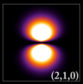
ALQ-184 (and I assume -131) act generally in the direction of their fore/aft antennas. It's a picture of an electron orbital but roughly the shape I mean: Abeam is not so good. No idea how ALQ compares to internal (some F-16 have internal as well). I agree that EW sounds like a challenging pursuit.
-
97s are set on the ground. You can change what the airplane thinks the BA is on the SMS CNTL format but the weapon is unchanged. I don't think the CNTL page is modeled yet. There is no data connection between airplane and weapon.
-
Missing implementations in the UH-1H Huey module.
Frederf replied to Calabrone's topic in DCS: UH-1H
I would like the IFF switches fixed. They used to move correctly until a more recent version and now knobs turn the wrong way and stop at wrong positions. I know it's just eye candy until if/when IFF becomes a real thing but sometimes I like to keep the habit up. Plus it integrates with Lot4ATC. -
The only time the airplane moves the trim wheels automatically is the pitch wheel to zero during the takeoff roll. Every other time the trim is only moved by pilot input manually. Other behavior would be fictional. Such features could be added as convenience options but I don't anticipate they are all likely.
-
Yes, it should jump highlight to first detent on the first half of trigger motion and jump highlight to second detent. The highlight jump occurs when a new down context event occurs. You won't be able to tell if upon pressing the second detent if the first detent remains pressed or not using DCS's control menu. If the laser doesn't work on full trigger action then you know it's changing output instead of adding. Also you can look at joy.cpl in Windows to see how the buttons are being processed by Windows (or any realtime joystick monitor). DCS expects that both buttons are status ON when trigger is at full action.
-
The ACTIVITY word above the ACT/PWR label should flash when illumination activity is detected. The POWER word below the ACT/PWR label should illuminate when the RWR is powered. I know the POWER word below the neighboring POWER label sounds redundant with the ACT/PWR POWER word but I think they refer to slightly different statuses. E.g. the POWER-POWER is the whole system power which comes on immediately and ACT/PWR-POWER responds perhaps slightly later if a particular part of the system is powered. These two lights on this button don't seem to come on under any condition currently.
-
AGM 65 E drifts when flanking the target during lasing
Frederf replied to gemballa974's topic in General Bugs
This is due to DCS's funny way of putting the laser reflection as a jewel on the end of a stick. In the simulation the laser reflection spot can be in mid air and that's what you're seeing here. The stick length in DCS is a maximum of 8nm and if the line of sight to the target is >8nm then the last spot just hangs in mid air at 8nm from the source. If you were to keep the target no more than 8nm away throughout the designation you would see normal behavior. -
It should be -1.5°. For some reason the angle scale was changed from degrees to tens of mils some time ago. "10" on the scal means 100 mil as can be compared to the fixed reticle ring. 1.5 is 26.666 mill or 2.6666 on the current angle scale. Checking it's sorta "25" but I'm pretty sure it's 'centiradians', definitely not degrees.
-
Whoops, forgot file F16 VRP 12-6B.trk
-
My track does. I probably moved too quickly. I also didn't make too much fuss about the precision as my slews were very large. I'll make another slower one. I never saw the Syria track because it requires that I own the Syria terrain to view it. Be aware there is another bug related to the radar where it doesn't move the imagery properly until 1 or 2 azimuth sweeps are completed. The cursor will appear to "snapback" after slewing until the picture updates which makes refinement of the cursors more difficult to do precisely as it would otherwise be. The cursor placement isn't as it appears until you allow the radar to do 1 or 2 passes after the last time you slewed. DCS radar doesn't do FTT mode fully yet. The TMS forward from GM/GMT/SEA produces a sort of middle ground freeze that I've seen documented for AGP-66 MLU radars. Proper "full" FTT completely blanks the display except for the target diamond and crosshairs and is in a B-scope format not PPI. But to your question, with MARK DED page open, TMS aft should not change the selected marking sensor as it does. TMS forward should not record coordinates onto the next markpoint slot until the radar is already in the locked state. I.e. the first TMS forward from a searching GM radar would enter a track mode and only the second would record coordinates for the mark point. In this way the radar can be locked/unlocked any number of times without recording coordinates. Pressing TMS aft should have no effect on the mark mode as it is strictly a radar control input at that point. It should not change the marking sensor to HUD. The only way to do that directly would be to SEQ from FCR to HUD. F16 FCR mark and CZ2.trk
-
Provided track has TGT defined by STPT 1 center of runway ahead. RP is defined as 90.0°T 6000' relative to TGT/STPT. RP is selected as sighting point. On run in TD box is seen geographically correct as target at center of runway and steerpoint. RP diamond is seen geographically correct as one mile east. However CCRP aiming is directed in error toward RP and bomb delivered normally lands at RP location. This should never happen as OA1, OA2, RP, or IP are never the weapons target and no bombs should be directed at them in any circumstance. What should happen as RP/TGT are cycled is that ASL remains unchanged as aiming direction towards target location. Sensors follow sighting point, ASL doesn't.
-
I'm getting a crash on sighting point change too: https://forums.eagle.ru/topic/287564-crash-cycling-vrp-sighting-point/ I don't believe that crashes have a saved track. In several important ways DCS VRP and VIP is working correctly and in several important ways it is not. Judging by the "IP" on OSB10 label you are in VIP mode, not VRP. But in either mode the IP/RP and the TD symbols should move smoothly and continuously while slewing the TGP. The symbols should always be pointing at the sensor sighting point at all times. Pressing CZ should cause both symbols and sensors to jump back to their zero-slew positions together. Here is a track demonstrating how the symbols should move together with slewing. By changing the sighting point the sensors will jump to the other sighting point. This is normal and correct. What is incorrect in the attached track is that the weapon aiming cues (ASL, etc.) are changing based on the sighting point selection. In the real airplane the weapon aiming and weapon delivery are always to the target, regardless of sighting point selection. In VIP there is some navigation to the sighting point but never, ever weapon delivery. F16 VRP 12-6.trk
-
Have you seen my track? It's an example of an FCR mark and mark was accurate.