AeriaGloria
-
Posts
5886 -
Joined
-
Last visited
-
Days Won
2
Content Type
Profiles
Forums
Events
Everything posted by AeriaGloria
-
Potential mistake in MiG-29A FAQ about R-27ER and R-27ET
AeriaGloria replied to quantum97's topic in DCS: MiG-29A Fulcrum
Yeah, and only missing radar mode is SP which even domestic models were made without sure third batch. Radar, TP, CC, Helm, Opt, Fi0, toss, 6 modes!! Every manual I have read fire all the sub variants sure identical radar range -
Wonder if anyone has more insight then I have been able to glean from manuals. In FC3, I’m sure I’m not the only one that likes to constantly switch sensors. If I am in position to have IRST lock, but need to get closer, I might acquire with radar, switch to IRST, then either fire fox 2 when ready or fire fox 1 and have it switch to radar leading. And I’m sure EVERYONE has to atleast do this to IFF an IRST target. And for FF, this won’t change in that, as long as IRST is leading, you won’t get IFF. So, unlike FC3, where one sensor will pick up lost lock of other in any mode, this only happens in IRL and FF if we flip the cooperation/interaction switch forward, which will lock radar to MPRF. And HUD scale to 25 km. This seems like a meaningless gimp and asinine and dumb! Right? But it almost makes sense, MPRF range is anywhere from 18-35 km depending on altitude, background, RCS, etc, so this roughly lines up with IRST range well, though I expect many times to have IRST outrange against a rear aspect AB target. So, let’s say we acquire with IRST and need to IFF, or acquire with radar and go to silent running with IRST? After all, there are no simple radar and IRST on/off switches like FC3 leads us to expect. What I’ve figured out so far is…….. TP (IRST) mode: Switches to radar if Fox 1 selected Permanently switches to radar if Press lock before laser range RL mode: Select Fox 2 and move SUV knob to TP will switch to TP leading IF TP selected and entered RL by selecting Fox 1, selectingFox 2 will go back to TP leading Its possible TP may be forced temporarily by lowering gun trigger I also have a hunch that even without the cooperation switch, Fox 1 selection might just switch to radar no matter what. Manuals mention this frequently enough. And Su-27 does same thing. Also, complications that, I don’t know for sure but it’s possible that even without interaction/coop switch the radar may take up to 8 seconds to range an IRST target beyond laser range. Or it might be instant as long as coop switch is on It’s a shame it can’t IFF while doing its 3 seconds ranging pulses…… So, if out of Fox 1, sucks to be you If out of fox2, also sucks to be you! I wonder if you fire your last fox 1, it switches to TP, you lose TP lock, then it switch back to radar as long as coop switch is forward It’ll be interesting to see how it’s implemented on release! It’s the big unknown for me along with things like “will RWR be able to tell you about missile launches” and “will RWR actually put PD fighters in medium range SAM category beyond 20 km, or both categories light up.”
-
Every Mi-24 manual I have e read says keep it in MK unless above 70 degrees latitude or around magnetic anomalies. Mi-8 is a little different. That’s all.
-
Yes, mag deviation changes with date I prefer to stay in MK mode for accuracy
-
R27R/ER lose track if you enter memory Mode
AeriaGloria replied to GRY Money's topic in Su-27 for DCS World
But wouldn’t it send out pseudo CW and datalink at same time? I don’t see why it would separate them -
Hello, this video covers the unintentional “Cobra maneuver” of the Mi-24 when pulling back on the cyclic, why it happens, and how to prevent and recover from it!!!!!! With this you should be able to turn and burn to its maximum performance!!!!! Enjoy the opening!!!!!!!! https://youtu.be/cxVypUj-_Lk?si=dx0trxzmsfCz_dw5
-
MiG-29 radar is weird. as far as I can tell, 65 degree azimuth limits is only for search, it goes to 70 degrees as soon as you track. Sam for elevation, only -36 degrees in search, goes to -45 in track. I would only really use the downward limit for tracking a low target from high altitude or lofting R-27R/ER
-
What is the MAR for an AIM-7M/MH Sparrow in DCS World?
AeriaGloria replied to CommandT's topic in Sim Research
Fly and wire gives from 10 nm at low Altitude to 16 nm at high. This seems quite over estimated to me though, I have gotten away with half these values -
It represents the gimbal limit. So when on left/right border of the HUD the target is 70 degrees to the side. When at the top/bottom the target is 60 degrees to the top/bottom. In the FF though the top/bottom borders will actually represent 45 degrees, as the radar can only point 45 degrees down. Since gimbal limit is represented by diamond in FF, it will be a bit harder to use on a left crank as the HUD has no right border, and thus you will need to look at the HDD to see the right HUD border there for FF.
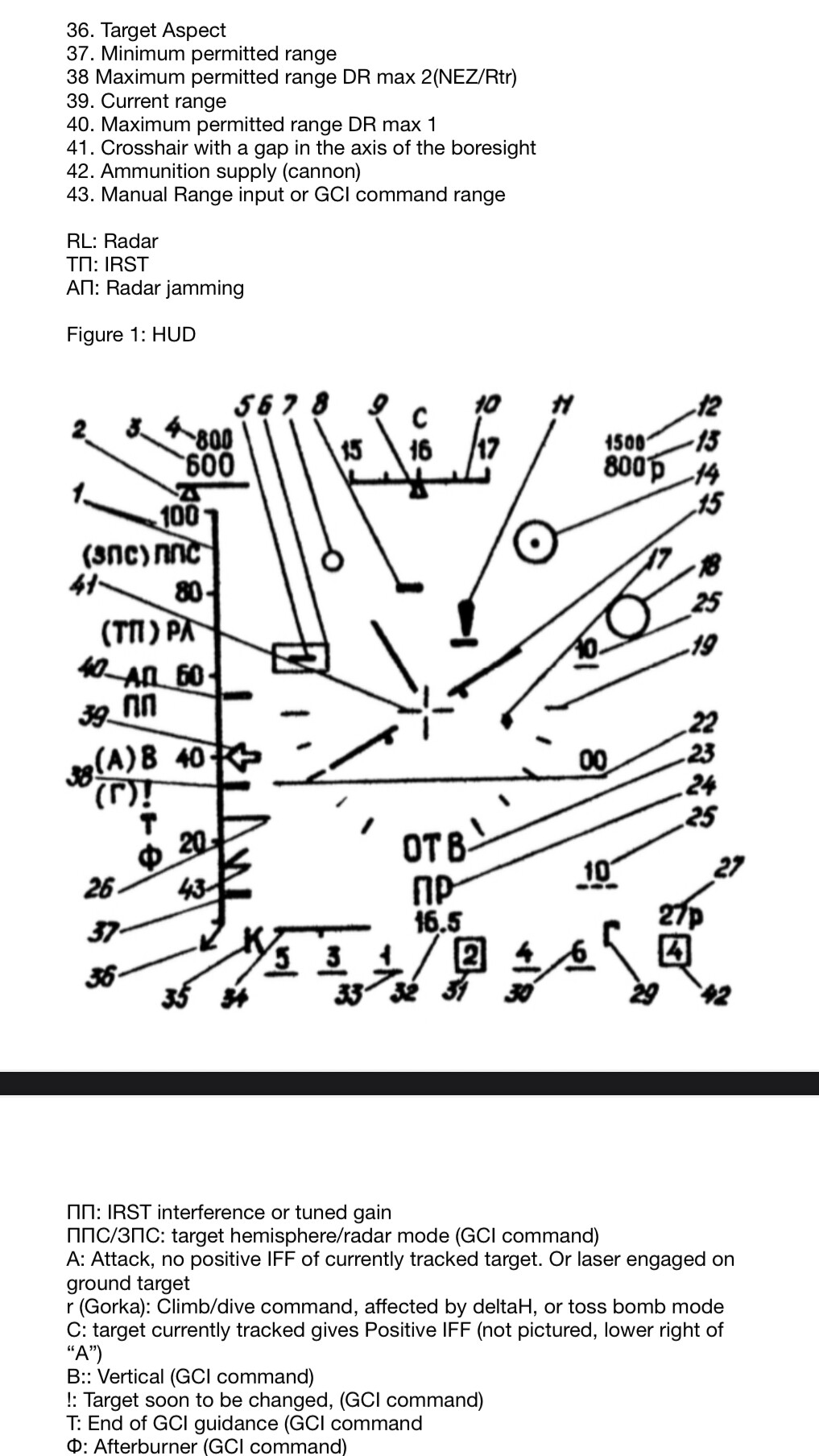
-
I understand. Just thought I could help. Regardless my AP document could serve as a thorough manual for the AP system. And some of my YouTube videos can provide information for other respects. And anyone is free to pick my mind for other stuff.
-
I am your manual!!!! What you want to know?? I wrote a guide on autopilot and weapons, translated the aerodynamic manual, and have a YouTube with currently 6 videos about the Mi-24. I’ll answer any question you have! https://youtube.com/@aeriagloria?si=Kod06Sp_eegzBJe7
-
Doesn’t work in FC3 or in FF. in FC3, the R-27R/ER goes completely dumb as soon as you exceed gimbal limits. Going back into them before memory mode expires does not fix this. In FF. It should completely drop the lock. What? The circle should give you perfect gimbal limits in FC3 29. When it reaches the HUD borders you’re at the limit. It’s just not there with IRST lock. And you didn’t say you meant only for FC3!!!!! The only way you’re going to work off bullseye with MiG-29 is if it’s set as your waypoint. Here target is within 12 degree HUD area, so circle is relatively close to center

-
1. In a mission, fly a specific altitude, airspeed, over a specific landmark pitch up to a specific angle at about 1.4 G. 2. fire the rockets and press active pause to use ruler and see how far the rocket type goes 3. Write down the distance with the altitude and speed you started at Usually 20 or 30 degrees is best.
-
I was reading recently that it does take the parallax into account, and even takes wing bending into account.
-
The most complicated part will be switching between Radar and IRST lock. It’s pretty complex all the different ways it can be done.
-
I do know that the scroll wheel has a press action to enter range. So perhaps you see no range number and/or bar, you press the wheel and they show up. You scroll it to choose range then press it again to enter into the system and the numbers and/or range bar then disappear.
-
Brazilian missile never happened. They couldn’t make it due to US sanctions on the needed anti radiation equipment. Replaced with LD-10
-
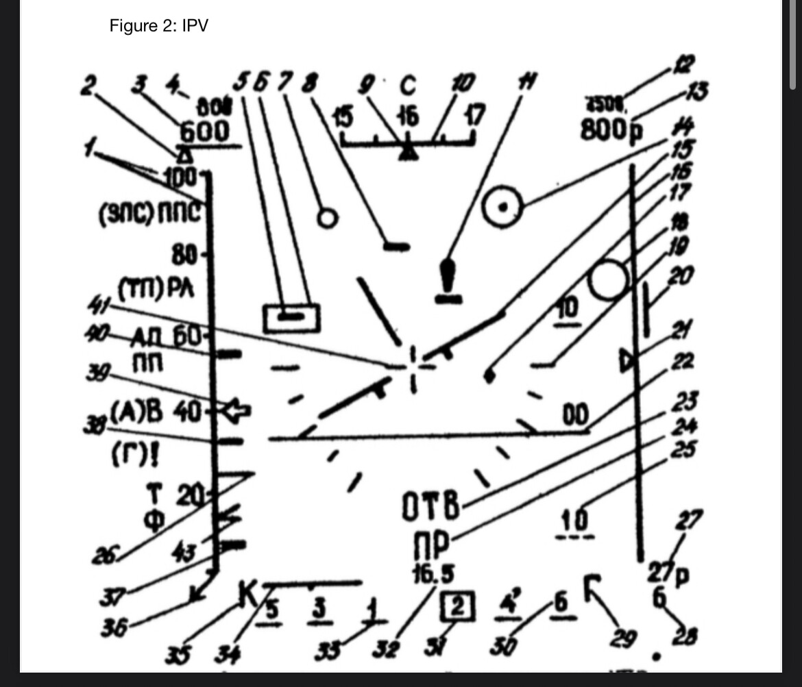
HUD: No target speed/alt without datalink. No target overlayed symbol. Right side of HUD is only on IPV/HDD. Symbology is only correct for level flight. Heading tape goes away with lock. No radar mode displayed, can only tell by fixed radar range in each mode. No target aspect in IRST mode, IRST mode ranging is uncertain beyond 6.5 km and might take 8 seconds or alert enemy RWR. No specific ATK symbol to show memory mode. Bar scanned on HDD/IPV. Rhombus is radar gimbal limit. RWR: No EWR or AWACs categories. Sides and rear have less range then front. 50/90 doesn’t show target at 60-80 degrees but actually 80-100 degrees and only at close range, 50 light only at medium to long range. PD fighters are misplaced in medium range SAM category until close range. Presence of missile tag showing estimate of enemy attack distance. Signal strength no longer shows linear distance but exponential. Possible blinding at close range. Elevation showing only works at close range. Low SHORAD priority. Sensor interaction: You do not have simple on/off control of radar and IRST to switch primary sensor. What is primary sensor will be decided by placement of SUV knob, whether in search or track mode, selected weapon, if laser range is present, and placement of interaction switch. In addition, one sensor will only pick up the lost lock of another sensor if you turn on interaction switch. Which locks radar to MPRF. Some things for people to expect
-
I have a YouTube where I’ve been releasing helpful videos for the Mi-24, I plan to switch to MiG-29 shortly before its release. I first plan videos best speeds and most efficient BVR profile, then perhaps RWR and HUD, sensor interaction use, etc
-
Another thing I have no idea how will they model it, if selecting Fox 1 forces you’re radar on. Meaning switching SUV mode will only work with Fox 2 selected. Also who knows if they mode the SPO-15 only having 90 degree light up with 50 at close range, and at medium to long range a radar at 90 degrees only lights up 50 light. Or if PD fighters will be in Hawk category until close range 15-20 km. Also don’t know about altimeter, their pre order video shows altimeter as exact as FC3. But watch videos of the HUD and you will see baro alt only does 100s, and radar alt only does 10s. I was talking earlier about how the HUD basically shows symbology as if you are level, here is a video showing it. He locks a target and turns right with 90 degree bank. Does the gimbal indicator and missile circle move down where the target is? No, it drifts to the left of the HUD reflecting it hitting the 70 degree gimbal limit of the radar. I think Su-27 can do it like we have in FC3 where it shows true direction partly because its radar has 60 degree gimbal limits in every direction. There is also this description of the HUD in L-18 manual, but combines IPV/HDD and HUD. Shows IFF symbol though. But on an old software update. There was a late 80s software update, a software update I’m sure we will get as it has other features like KMOD and R-27ER support that have been promised. This software update changed the IFF “C” from the left to the top middle of the HUD. It also switched around the large and small circles for a few things which has lead to so many things disagreeing on what they are used for. I bet people on release will wonder why they can’t shoot at a target, and miss the IFF “C” in the middle!
-
It’s hard to say. It seems the long horizontal line on the range bar represents set range. I wouldn’t be surprised if it ends up being just the horizontal line on the range bar, or if item 32 (waypoint range) also shows the range at the same time. But from images of the HUD I find illustrated in manuals or docs, and in videos, I do not see these numbers present during the search process. People are in for a big surprise. Like how the whole right border is only shown on HDD, namely the elevation/HUD elevation index and radar search elevation index. Or the HUD not showing target speed, alt, or even overlaying a symbol on target position (unless in gun mode and range, and only showing speed/alt with datalink). The freaking heading tape goes away when you lock someone! Guess they thought it was clutter to know where you’re pointed and it’s totally fine to look down while targeting someone! Also found an interesting image about landing mode the other day, it says the large circle only shows direction to airfield RSBN, only small circle shows actual flight path along PRMG beacon. IRST lock doesn’t show azimuth, we’ll have to figure it out from relation of missile max range and NEZ and movement of the IRST gimbal indicator. That is, once we get a valid range which may take as long as 8 seconds beyond laser range or never until we do kinematic range finding! It never says radar mode, you just have to figure it out from the range scale on the HUD! It will only say PPS/ZPS with datalink, and that is more telling you target hemisphere. But hey! It’ll tell us bar being scanned atleast! On the HDD…… So much for overlaying a symbol on the target being a wide spread feature of all 4 th gen’s, even F-14 HUD shows you closure rate! I personally plan to take advantage of TWS mode to make up for not knowing target speed, that way it will automatically pick the target with highest speed/range, and I won’t accidentally lock someone who isn’t the greatest threat to me. I asked a MiG-29 pilot once about not having any symbol that overlays the target, and he just said “it takes great skill to make visual contact!” Also all symbology is only valid if level. For example, if you lock someone in FC3, and turn away from them with 90 degree bank, the gimbal indicator will be on bottom of HUD becuase that’s the true direction to target. But the real MiG-29, as you turn away, no matter the bank angle, the gimbal indicator will drift to the left of the HUD. Ironically, I think this will make cranking and reversing cranks easier in Fox 1 combat. But the same applies for missile circle.
-
I think 32 is right, but yes that first instance of 42 seems to be a typo. The next instance correctly identifies it as either bad or cannon round indicator. Here is original We must remember though that whatever FC3 taught us about the HUD is wrong. It is really more like a watered down Su-27 HUD with MiG-29 symbols. In the L-18 manual and its description of the HUD, those central numbers are called only “distance to turning point of the route in navigation/landing mode”
-
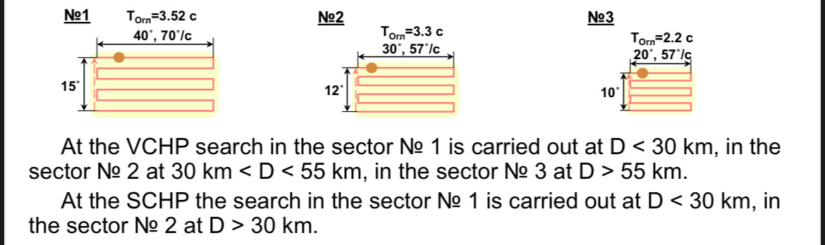
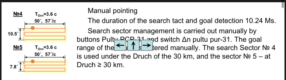
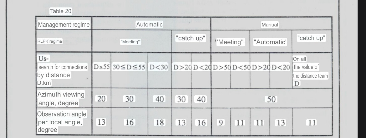
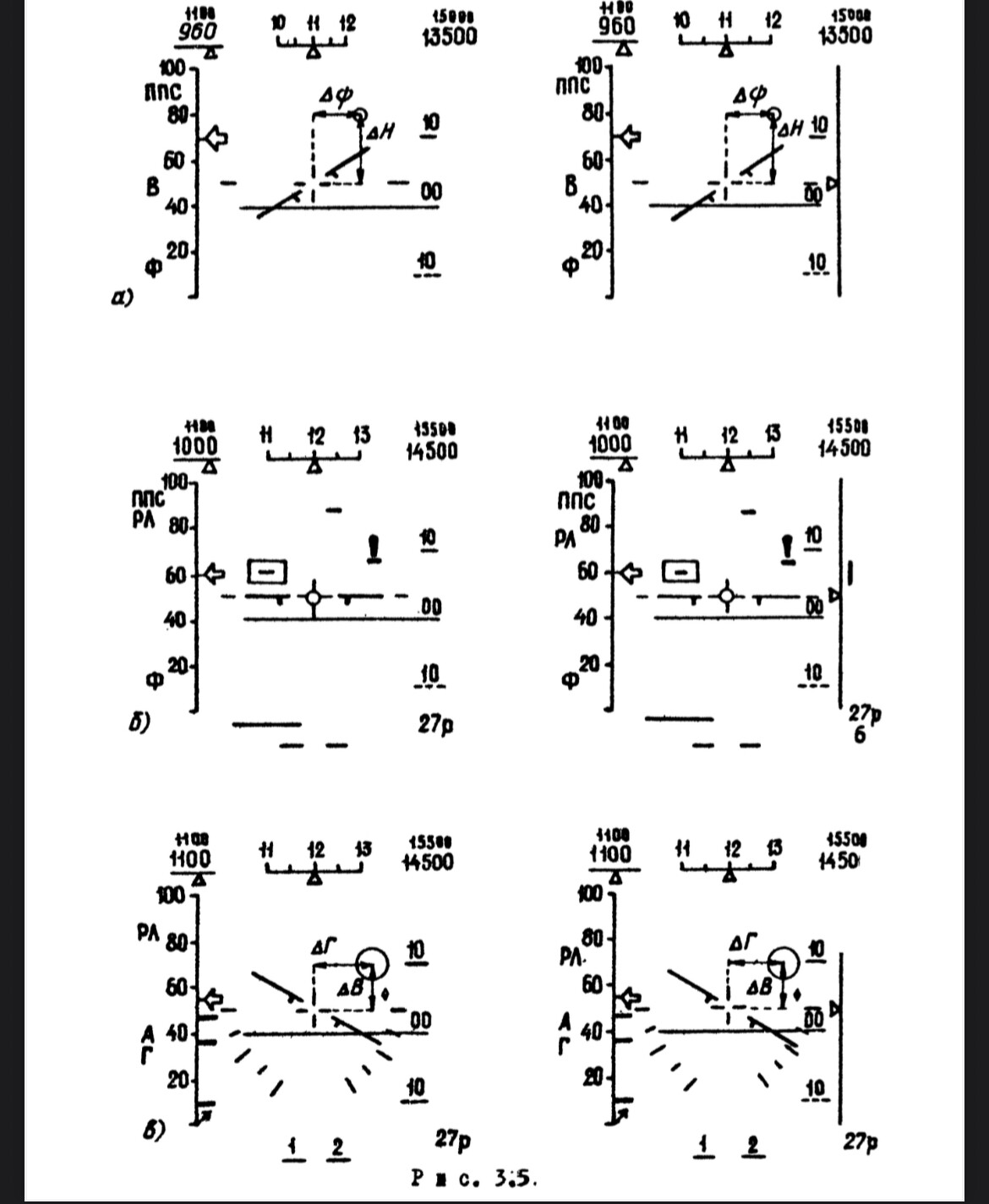
Yeah just be aware this is for Lazur GCI guidance. For non GCI guidance the combat employment manual gives the single 11 degree elevation 50 degree wide scan number. You see different numbers all over the place, I suppose if I went through the list of software updates with a fine tooth comb I might find something about it. For example this is from a PowerPoint from a Ukrainian university, for instrument/GCI guidance and for non GCI guidance And here is what L-18 manual gives
-
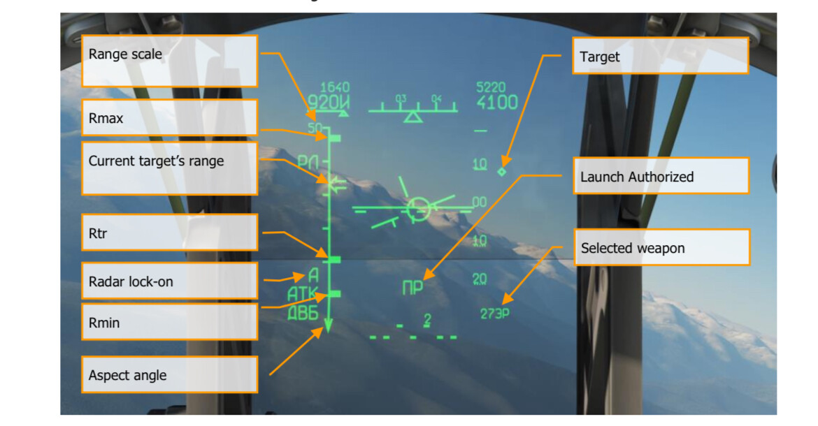
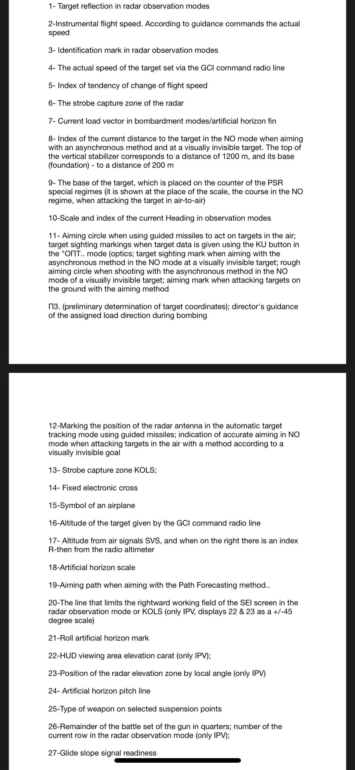
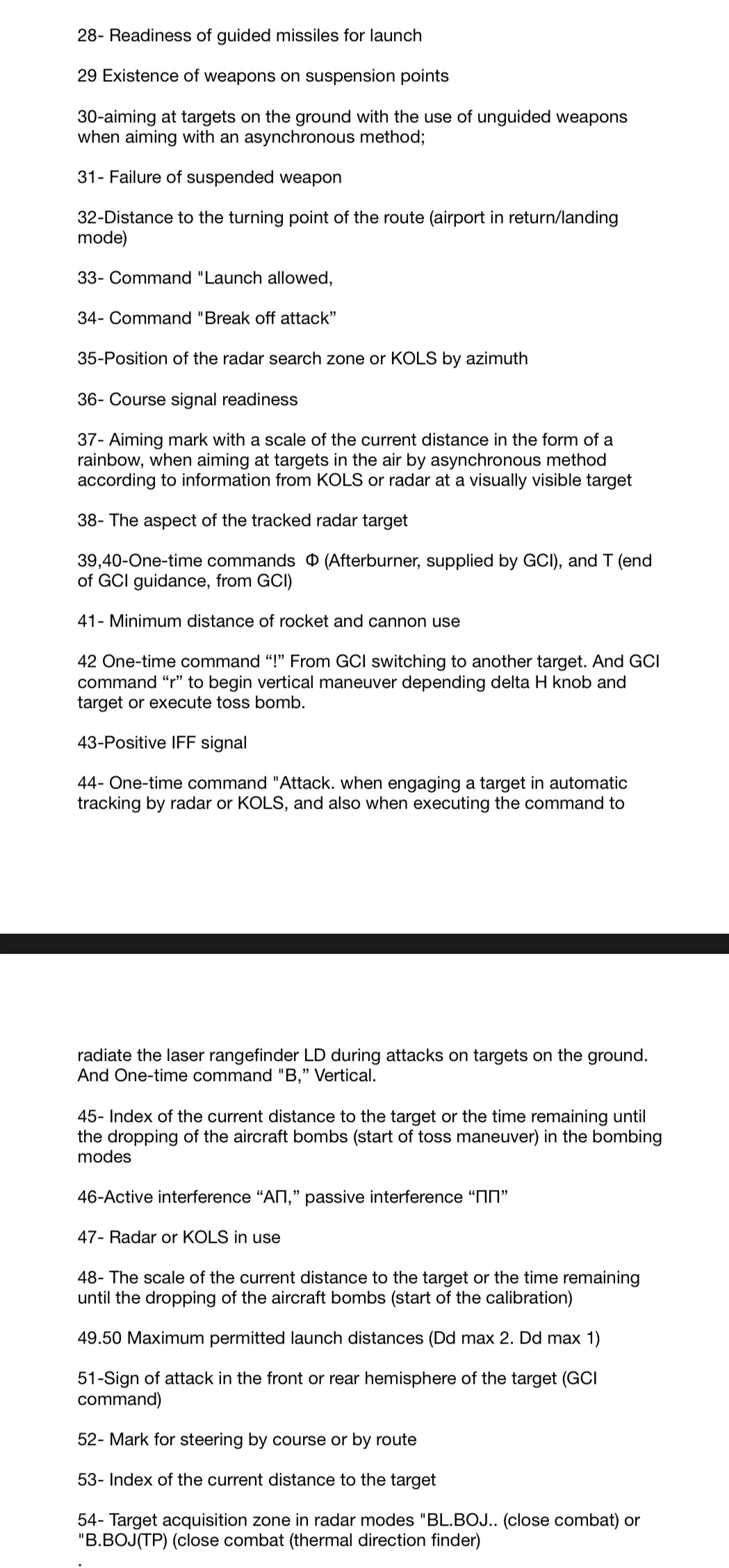
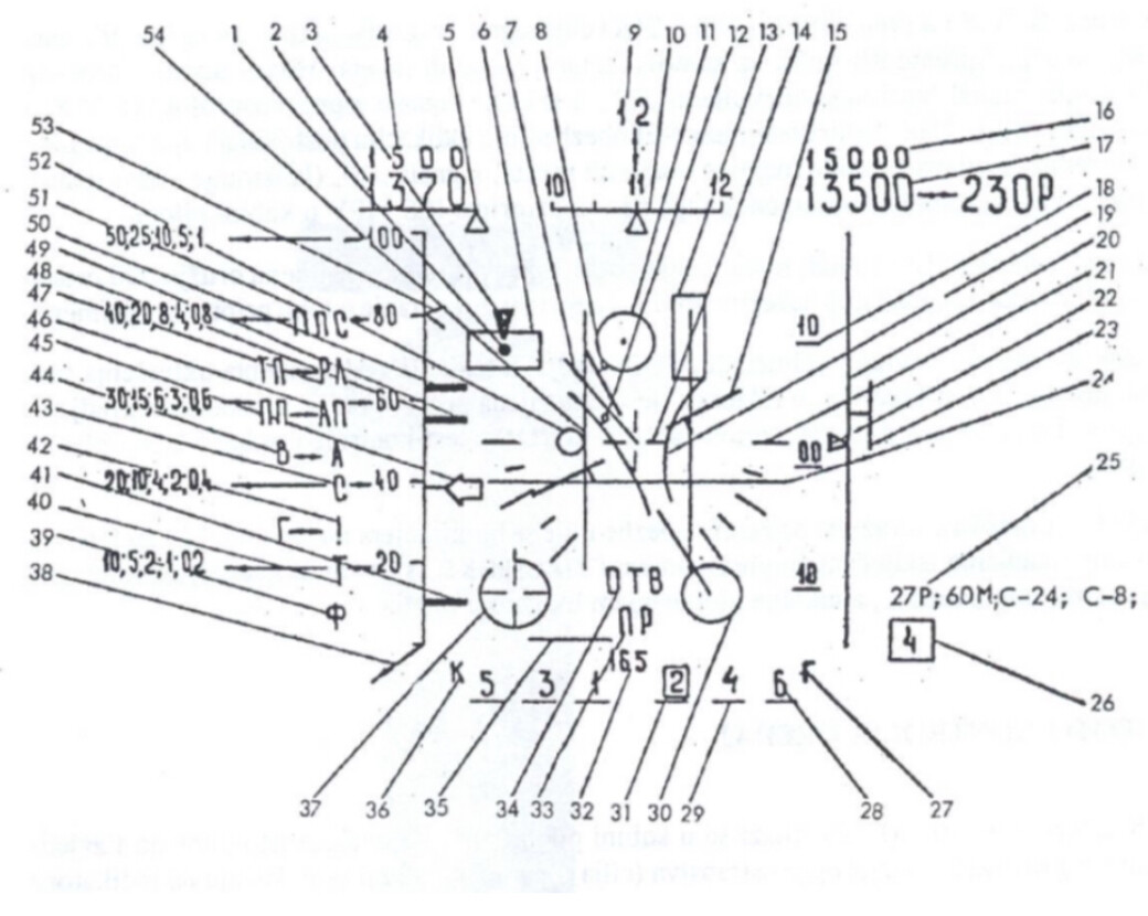
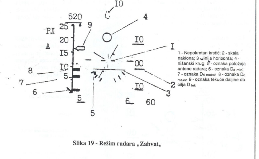
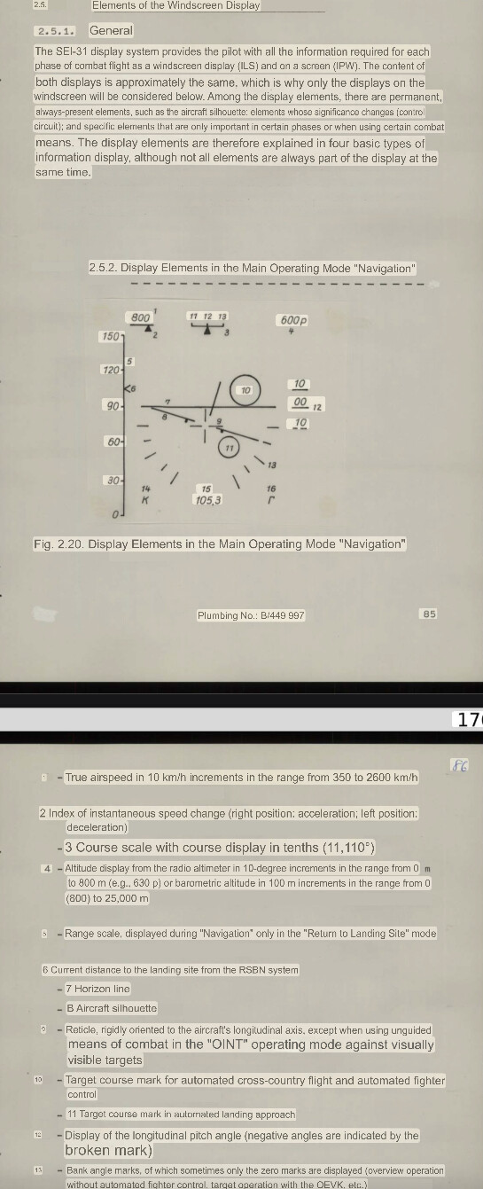
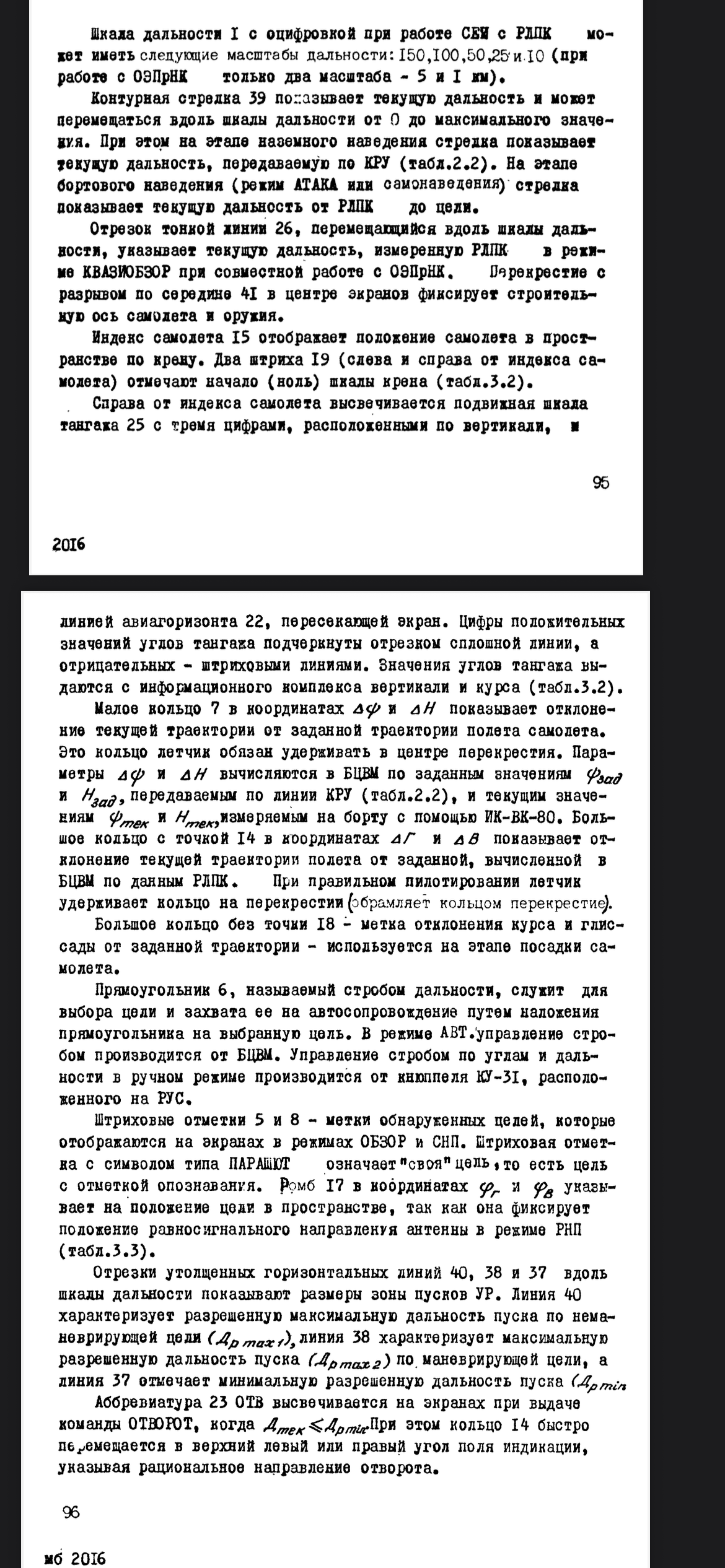
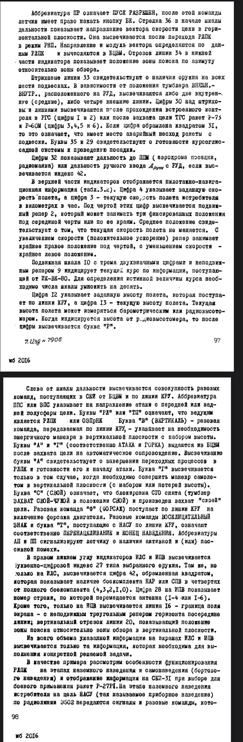
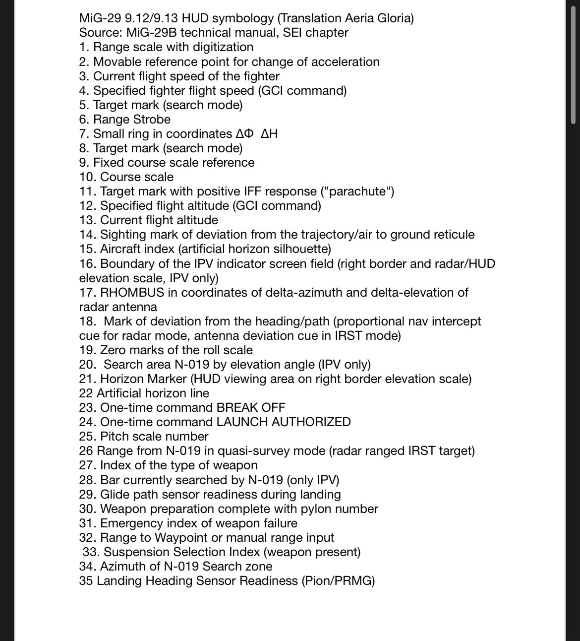
You would think but apparently the number (32) is just for navigation mode. Item 39 is STT range arrow, and item 43 is range from radar quasi scan. As you found item 26 is radar range that you set with the wheel or the GCI commanded range. This comes with some paragraphed that describe most of it “Range scale I with digitalization when working with SEI with the MO-ket radar has the following range scales: 150, 100, 50, 25 and 10 (when working with the OEPRIK only two scales 5 and 1 km). The contour arrow 39 shows the current range and can move along the range scale from 0 to the maximum value. At the ground guidance stage, the arrow shows the current range transmitted via the control unit (Table 2.2). At the on-board guidance stage (ATTACK or homing mode), the arrow shows the current range from the radar control system to the target. The thin line segment 26, moving along the range scale, indicates the current range measured by the radar in the Quazi scan mode in conjunction with the OEPRNK. The crosshair with a gap in the middle 41 in the center of the screens fixes the construction axis of the aircraft and weapons. Aircraft index 15 displays the aircraft position in space by roll. Two lines 19 (to the left and right of the aircraft index) mark the beginning (zero) of the roll scale (Table 3.2). To the right of the aircraft index, a movable pitch scale 25 is displayed with three numbers located vertically, along with artificial horizon line 22, intersecting the screen. The numbers of positive pitch angle values are underlined by a segment of a solid line, and negative ones by dashed lines. The pitch angle values are given by the vertical and course information complex (Table 3.2). Small ring 7 in deltaH coordinates and it shows the deviation of the current trajectory from the specified flight trajectory of the aircraft. The pilot must hold this ring in the center of the crosshair. The parameters deltaH and delta course are calculated in the on-board computer according to the specified values from the GCI command line(Table 2.2), and the current values of height and course, measured on board using the IK-VK-80. The large ring with point 14 at coordinates delta pitch and delta heading shows the deviation of the current flight path from the specified one, calculated in the on-board computer using data. During correct piloting, the pilot holds the ring on the crosshairs (frames the crosshairs with the ring).Large ring without point 18 - mark of deviation of course and glide path from the given trajectory of the aircraft. It is used at the landing stage of the aircraft. Rectangle 6, called the range strobe, is used to select a target and capture it for automatic tracking by superimposing the rectangle on the selected target. In the AVT. mode, the strobe is controlled by the on-board computer. The strobe is controlled by angles and range in manual mode from the KU-ZI key located on the RUS. Dash marks 5 and 8 are marks of detected targets, which are displayed on the screens in the REVIEW and SNP modes. A dash mark with a symbol like PARACHUTE means "own" target, i.e. a target with an identification mark. Rhombus 17 in coordinates 4 and 48 indicates the position of the target in space, since it records the position of the equal-signal direction of the antenna in the RNP mode (Table 3.3). The thickened horizontal lines 40, 38 and 37 along the range scale show the dimensions of the missile launch zone. Line 40 characterizes the permitted maximum launch range for a non-maneuvering target (Dr 1), Line 38 characterizes the maximum permitted launch range (Dr 2) for a maneuvering target, and line 37 marks the minimum permitted launch range (Dmin). The abbreviation 23 ОТВ is displayed on the screens when the ОТВОРОТ command is issued, or when Dmin is larger then present range. In this case, ring 14 quickly moves to the upper left or right corner of the indication field, indicating the rational direction of the turn. The abbreviation PR means LAUNCH ALLOWED, after this command the pilot has the right to press the BC button. Arrow 36 at the beginning of the range scale shows the direction of the target speed vector in the horizontal plane. It lights up after the RLPK switches to the RNP mode. The direction and module of the vector are determined by the RLPK data and calculated in the BCEM. Section 34 of line in the lower part of the indicator shows the position of the search zone in azimuth relative to the viewing zone. Dashed lines 33 indicate the presence of weapons on all six suspensions. Depending on the position of the EXTERNAL-INTERNAL toggle switchlocated near the throttle, either two internal (middle) or four external lines are illuminated. The numbers 30 above the dashed lines are illuminated after passing the built-in control in the RGS (numbers 1 and 2) or after target acquisition by the TGS of missiles R-73 and R-60M (numbers 3, 4, 5 and 6). If the number is framed by a square 31, this means that there is an emergency failure of the missile to leave the suspension. Letters 35 and 29 indicate the readiness of the course-gliding system to land. The numbers 32 indicate the range to the landing point (landing airfield, radio beacon) or the range of manual input of the control lever if the index 42 is displayed. The upper part of the indicators displays flight and navigation information. 4 indicates the GCI received speed, and 3 indicates the current flight speed of the fighter in kilometers per hour. Under the line of these numbers, a movable benchmark 2 is displayed, which can occupy three fixed positions under the middle of the line or to its edges. The middle position indicates that the current flight speed does not change. With an increase in speed (positive acceleration), the benchmark occupies the extreme right position under the line, with a decrease in speed, the extreme left position. The movable scale 10 with three two-digit numbers and a fixed reference point 9 indicates the current course based on information received from the IK-VK-80. To determine the true course value, the numbers on the scale must be multiplied by ten. The number 12 indicates the set flight altitude, which comes via the GCI command line, and the number 13 indicates the current flight altitude. The current flight altitude can be measured by a barometric or radio altimeter. When the altitude from the radio altimeter is indicated, the letter "P" is displayed after the number. To the left of the range scale, a set of one-time commands coming to the SEI from the on-board digital computer and via the control switchgear line is displayed. The abbreviation PPS or ZPS indicates the direction of attack from the front or rear hemisphere of the target. The letters "PL" or "TП" mean that the RLPK or OEPRNK is leading. The letter "B" (VERTICAL) is a one-time command transmitted via the control GCI line, indicating the need for an energetic maneuver in the vertical plane with a gain in altitude.The letters "A" and "r" (ATTACK and HILL, respectively) are issued from the on-board digital computer after target acquisition for automatic tracking. The display of the letter "A" indicates the completion of transition processes in the RLPK and its readiness to begin an attack, or laser emission. The letter “r” is displayed only when it is necessary to perform an aircraft maneuver in the vertical plane (with a gain or loss of altitude). The letter "C" (OWN) means that the “lock only negative IFF” switch is removed (the OWN CAPTURE switch is in the OWN position) and the "own" target has been captured. A one-time command "Φ" (FORSAH) is sent via the GCI line to turn on the engine afterburner. The one-time commands “!” and the letter "T" coming from the ground station via the GCI line mean RETARGETING and END OF GUIDANCE, respectively. The abbreviations AП and ПП signal the pilot about the presence of active and (or) passive interference. In the lower right corner of the HUD and IPV indicators, the alphanumeric index 27 of the selected weapon type is displayed. In the same place, but on the HUD, the number 42 framed by a square is displayed, which shows the presence of NAR or gun ammunition in quarters from the full ammunition (4,3,2,1,0). The number 28 on the IPV shows the number of the line along which the antenna moves (1-4 or 1-6). In addition, only on the IPV is line 16 displayed - the border of the screen field with a fixed triangular horizon reference in the middle of the line; a vertical segment of line 20, showing the position of the search zone relative to the viewing zone in the vertical plane. Of the entire volume of information indicated on the ILS and IPV screens, only that information is displayed that is necessary for completing a specific task being solved is displayed. As an example, let us consider the features of operation at the stages of ground guidance and homing (airborne-RLPK guidance) and the display of information on the SEI-31 when selecting R-27RI missiles for combat use. At the stage of ground guidance of the fighter to the GCI target (the so- called instrument guidance), signals and one-time commands are transmitted via radio line 3502, which are intended for controlling the aircraft, the RLPK complex and weapons. Information intended for controlling the aircraft at the ground guidance stage is shown on the ILS and IPV indicators, shown in Fig. 3. Let us consider in more detail the set of commands intended for controlling the RLPK. Note that the receptionand processing of transmitted signals and commands will be possible only when the GUIDANCE toggle switch on the PSR-ZI console is turned on and the IZL. EKV. OFF switch on the PUR-ZI is set to the EKV position. After the fighter is brought into the zone from which it can make radar contact with the target according to the GCI 3502-20 data, target designation signals are transmitted to the antenna system of the radar control system (B; Σ (Table 2.2)) and commands for remote activation of the BRAS transmitter for emission and line-by-line movement of the antenna. If the KRU operates in the LAZUR mode, then emission is activated by a set of commands "100" ("60" or "36") and PPS when intercepting a target from the forward hemisphere or commands "36" and ZPS when intercepting a target from ZPS. In the first case, the VCHP operating mode is automatically activated (if the switch on the PUR-ZI is in the AVT position), and in the second case, the SCHP operating mode. Thus, the radar control system begins to operate in the REVIEW mode, the detected targets are displayed on the ILS and IPV screens (Fig. 3,5,6). The range strobe is automatically set to the specified target if it does not respond to the IFF system request. The pilot continues to fly the fighter according to the commands of the vertical ring, aligning it with the crosshair center. After pressing the MRK ZAKVAT PZ button on the throttle, the RLPK switches to the RNP mode. A large ring, missile launch zones appear on the indicator screens (Fig. 3.5, c) and the R-27RI missile radar operability check begins. Upon completion of the check, the numbers 1 and 2 are displayed. The pilot, placing the ring on the crosshair, attacks the target and continues approaching the target. When the current range is equal to or less than Drmax! the PR (LAUNCH ALLOWED) command is displayed and the pilot can press the BK button. For other operating modes of the control system, the indication on the IDS and IPV is similar to that discussed above” It is from the MiG-29B technical manual.
-
It is signified by a specific symbol on range bar, item 26 in this picture. Yes it does change that, but remember it changes much less and less drastically for manual radar control. Only GCI control really changes scan pattern vs range a lot. Fig 3.5 shows GCI intercept, left side is HUD right is IPV. It’s incorrect in showing heading tape while locked