Ramsay
-
Posts
3750 -
Joined
-
Last visited
Content Type
Profiles
Forums
Events
Everything posted by Ramsay
-
Not AFAIK. Instead you use the HUD and steering cue/tadpole.

-
10 days* is not a particularly long time given the nature of the report and size of Polychop • Posted as question, not a report • MP only, random (occurs 50% of the time ?) • No track, acmi or video to show target aspect, speed, etc. or how to reproduce Polychop is a small team (of three) and AFAIK the Gazelle is being "maintained" on a volunteer basis by a programmer using it familiarise himself with both the DCS code base and the Gazelle code. If you'd like to speed up the process, you can help by adding a track, acmi or video to this thread. * It was reported in the Gazelle bug section 3 days ago
-
1. Foogle already answered your question 2. Jet engines are more complex than a mechanical lever connected to fuel pump, when you move the throttle, you are actually moving a lever on the engine governor i.e. for 100% rpm/thrust. What this means for fuel delivery, etc. from the governor depends on • air temperature • air pressure • current rpm • etc. (i.e. I'm likely forgetting a few factors) The engine has various sensors fitted to measure these and "govern" it's speed i.e. when the pilot moves the "throttle" lever to 100%, RPM increases to 100% and holds steady, (i.e. the engine doesn't overspeed and destroy itself like most cars would if give full throttle while out of gear). I'm not sure on the conditions required for the JF-17's weapon system to reduce engine RPM to idle but IIRC in the L-39 they would be • Weapon System ARMED • Cannon selected • Speed Above 310 km/h (req'ed to fire the cannon) ... and when all 3 conditions are meet, the RPM will drop to idle when the Trigger is DEPRESSED. Comment I'm a little surprised the JF-17 reduces engine RPM when firing wing tip SD-10's but perhaps it's a disadvantage of mixing an older engine system with a modern weapons computer (i.e. it can't can't be hard wired for a particular weapon type/station) or is just another of the JF-17's "peculiarities".
-
No, however the question is outside my expertise, AFAIK it's usually a matter of FM tuning rather than something missing, and I have to be guided by the feedback given by RL Yak-52 owners/pilots who say there are things that could/should be improved (but none of that matters if ED feel their time/resources are better used elsewhere). For those who can, I suggest enjoying the DCS Yak-52 for what it is, rather than what it might have been.
-
Parasitic drag increases, AFAIK best glide is calculated at max. weight, so with less fuel, etc. the best glide speed would be slower, I did a zero fuel test as well but actually glided a slightly shorter distance than I had previously.
-
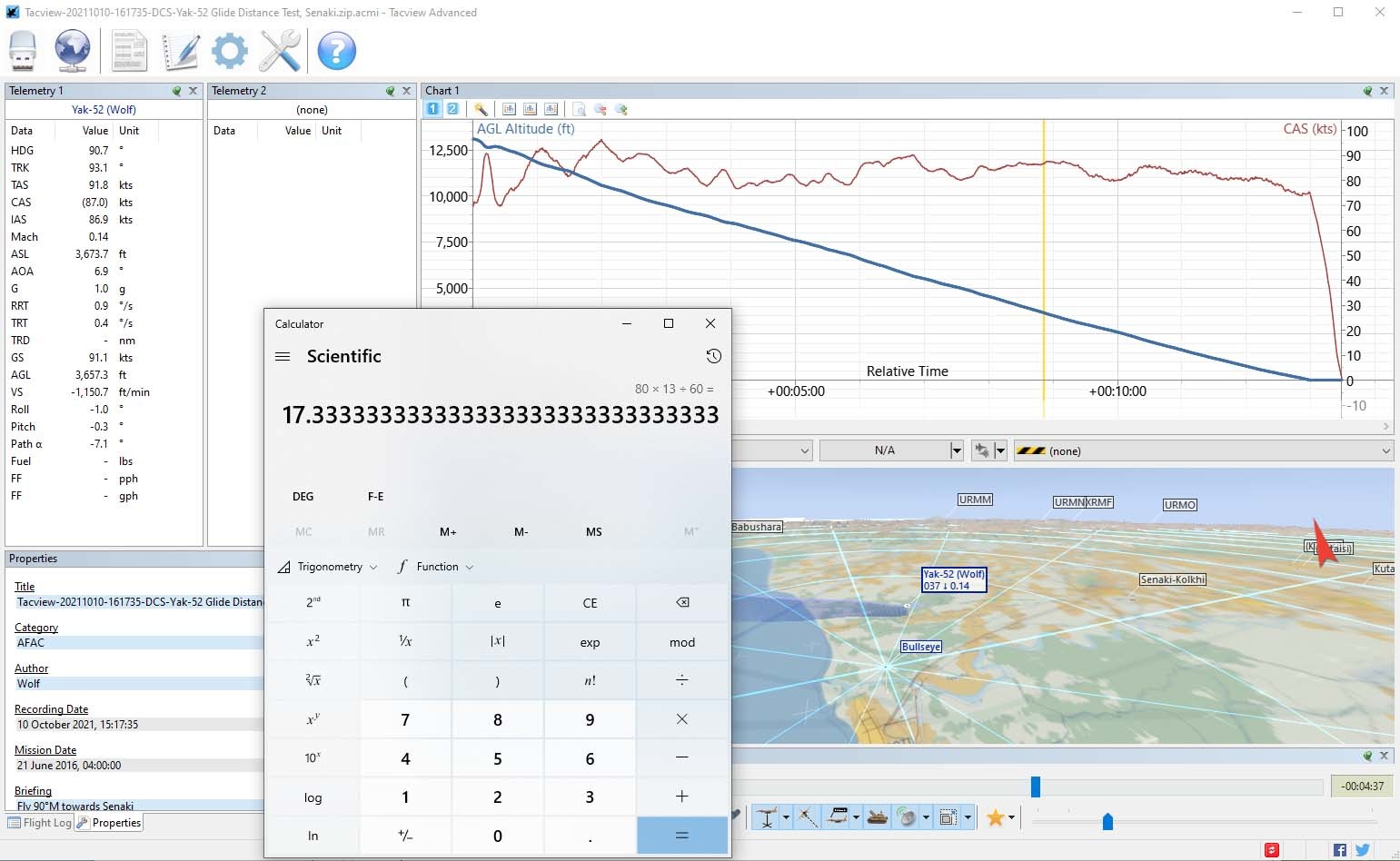
Testing in Open Beta 2.7.6.13436, I'm seeing a glide distance of approx. 17 NM (32 km) which is 20% further than expected from the POH but not nearly as bad. Perhaps the previously quoted 40km estimate was overly optimistic or something has changed since the video was made ?
-
Unlikely as the height of planes using Flight Level would need to change if/when the air pressure in the weather tab was changed.
-
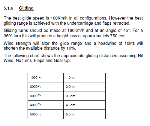
Best Glide Speed (Lift to Drag) is 160 km/h, so at higher speeds the increased drag *should* reduce the glide distance. In the video the engine failed at approx. 4,000 m and was able to glide approx. 40 km. • 4,000 m = 13,000 ft • 40 km = 21.5 NMI The expected glide distance = 5.5 NMI x 13/5 = 14.3 NMI = 26.5 km So the glide distance in DCS was 50% further than expected (assuming negligible tail wind).
-
Are this files DCS global or AV-8B specific?
Ramsay replied to DmitriKozlowsky's topic in Problems and Bugs
They are Windows operating system files. gpapi.dll is a Group Policy Client API. This file is part of Microsoft® Windows® Operating System. Gpapi.dll is developed by Microsoft Corporation. It’s a system and hidden file. Gpapi.dll is usually located in the %SYSTEM% folder and its usual size is 79,872 bytes. Gpapi.dll creates new records and folders in the Windows registry. Check your system performance to eliminate possible application conflicts and system failures. https://www.fileinspect.com/fileinfo/gpapi-dll/ -
Not AFAIK or at least not very well. See @myHelljumper's previous answer for how the current implementation is working.
-
ENT is a mix of HFR (High Pulse Rate) + BFR (Low Pulse Rate) scans • HFR scans use a doppler filter and display contacts like the current radar "V" • BFR doesn't have a doppler filter, so is similar to ground mapping/Visual mode There are couple of WIP videos of the WIP version of ENT on Razbam's Discord, there will eventually be a detail forum post on how all this stuff works closer to the release of the "new" radar modes, etc. This static picture doesn't really capture it but it'll give you an idea ... the chevrons are displayed by one sweep and the ground by another, IIRC the order/number of HFR + BFR scans depends on the radar settings, number of bars, etc., so you might get 2x HFR scans followed by a single BFR scan depending on where you are in the scan pattern. One thing to note that isn't shown in the screen shot above is that ENT only works out to 40 NM and reverts to pure HFR scans if the range is increased beyond that.
-
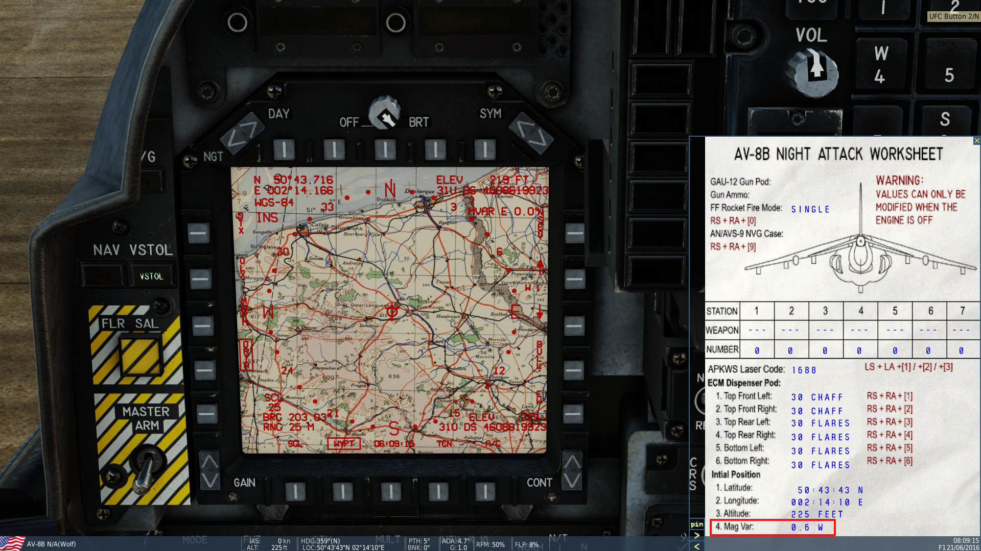
[REPORTED] Magnetic Variation issue in The Channel.
Ramsay replied to Draken35's topic in Problems and Bugs
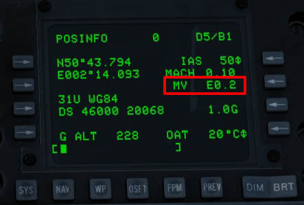
Your screen shots show a mission date of 2016, both in RL and in DCS, Magnetic Declination/Variation was close to zero at Saint Omer in 2016 i.e. Magnetic and True bearings read the same. Checking the position page of the A-10C shows that in DCS MagVar = +0.2°E at Saint Omer Longuenesse in 2016. This is consistent with the current (2021) MagVar of +1.02°E as the nearby Merville Calonne Airport (LFQT) shows an annual change rate of 0.19° Unfortunately, although the AV-8B's MagVar is very small, it doesn't match ED's "correct" declination value, instead the AV-8B's Kneeboard reads -0.6°W and it's EHSD map rotates ever so slightly when switching between True and Magnetic settings (which it wouldn't do if MagVar was correct).
-
I've always found compass behaviour inconsistent in the WWII maps, but couldn't tell if it was an issue with the map, the aircraft or a misunderstanding about the "correct" historic magnetic deviation on my part. I also have to admit to not noticing the problem on the modern Caucasus map as I usually (always?) fly the WWII warbirds using visual landmarks and only used the compass for the most basic of SA i.e. which way to look for a particular landmark, etc. So when looking at your initial reports, I certainly didn't expect to find such a pervasive problem or that Chuck's Guides for the FW190D-9 and BF-109K-4 from July 2019 would show the problem has been present at least since then. On the positive side, ED have marked it as a "known" issue
-
Still haven't found anything specific but am thinking ED might have modelled the mossie as using a Bendix Flux Gate compass or perhaps the simpler Magnesyn Compass ? If so, AFAIK it shouldn't show errors due "magnetic dip", acceleration, etc. Re: The Magnesyn Compass Think the base non-gyro stabilised, oil damped Magnesyn Compass still shows errors but they are reduced from those found with a "normal" magnetic compass. It's floating compass has 20° of freedom of movement, so I would expect it also to read accurately when stationary or in unaccelerated level flight.
-
TL;DR: You'll want to enter "Options>Controls>Mosquito FB Mk. VI Sim" and swap DCS's force axis outputs to match the MSFFB2. This post about setting up FFB for the Yak-52 covers it in more detail.
-
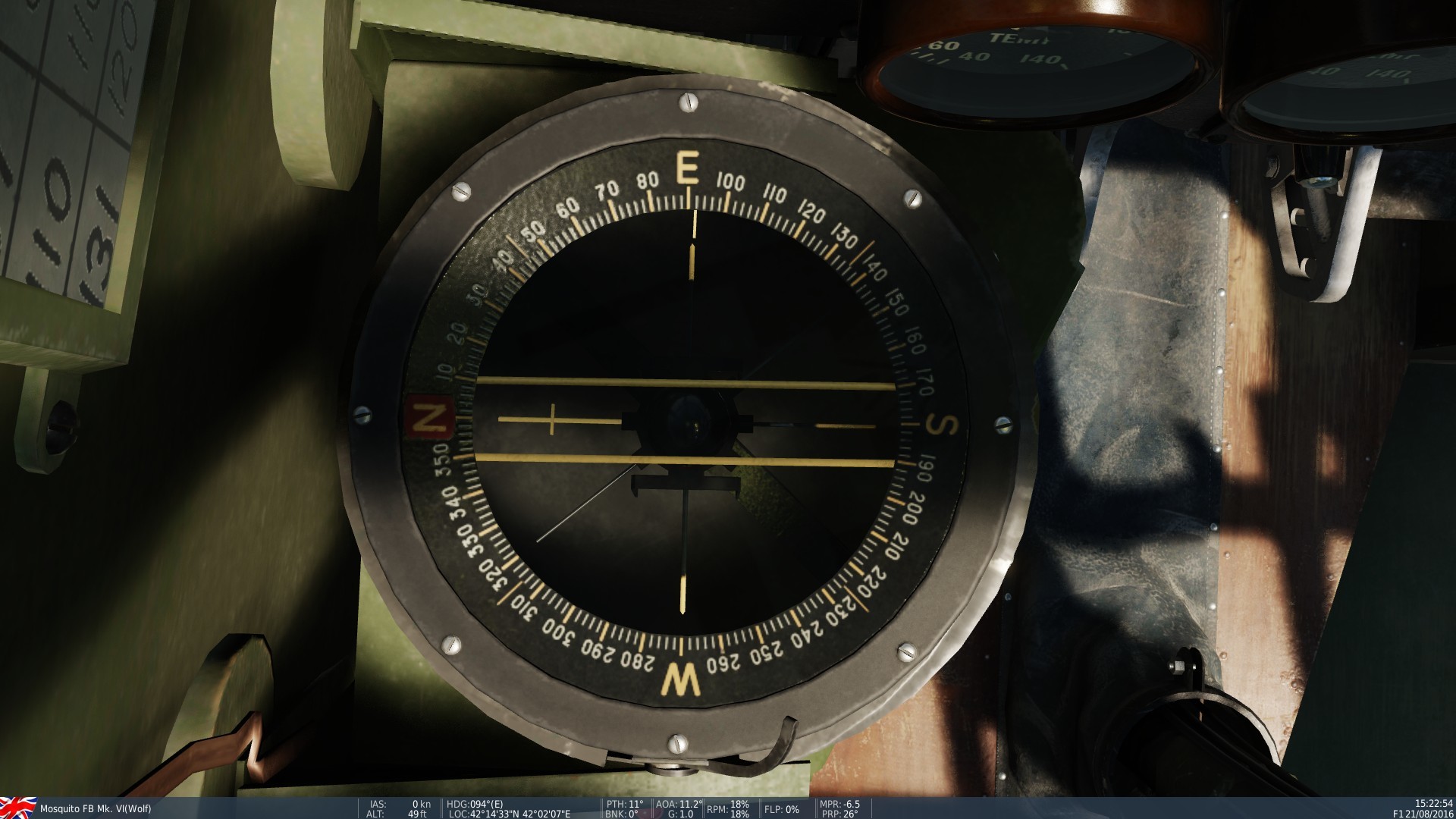
I haven't seen the issue with the base magnetic compass (Spitfire is hard to read) but the Mosquito and Spitfire Gyro Compasses are set "wrong" when spawning. Here the Mossie's magnetic compass reads approx. correct at Senaki (2016) 88°M / 94°T while the RI Compass Repeater and Gyro Compass read 115° and 122° respectively. I haven't found any details on the Mossie's RI Compass Repeater to find out if it's Master Compass is similar to the Bf-109's PFK/m I think ED are modelling "Magnetic Dip" which effect magnetic compasses under acceleration or in a turn, however it shouldn't effect them when stationary or in non-accelerated level flight. Magnetic Compass Errors - Acceleration Magnetic Compass Errors - Turns
-
This video suggests the daughter compass should read correctly when stationary and lined up for take off. Note • @0:17 the compass initially indicates the aircraft/runway heading • @0:47 As the aircraft accelerates to take off, the compass deviates (10-30°) due to the acceleration, • @1:05 Once airborne and flying level the compass pointer returns to it's previous heading until the pilot makes his turn. See my other post on how the RL Master Compass is gimbaled and how the DCS compass should likely read correct when the aircraft is stationary but I'm not a SME.
-
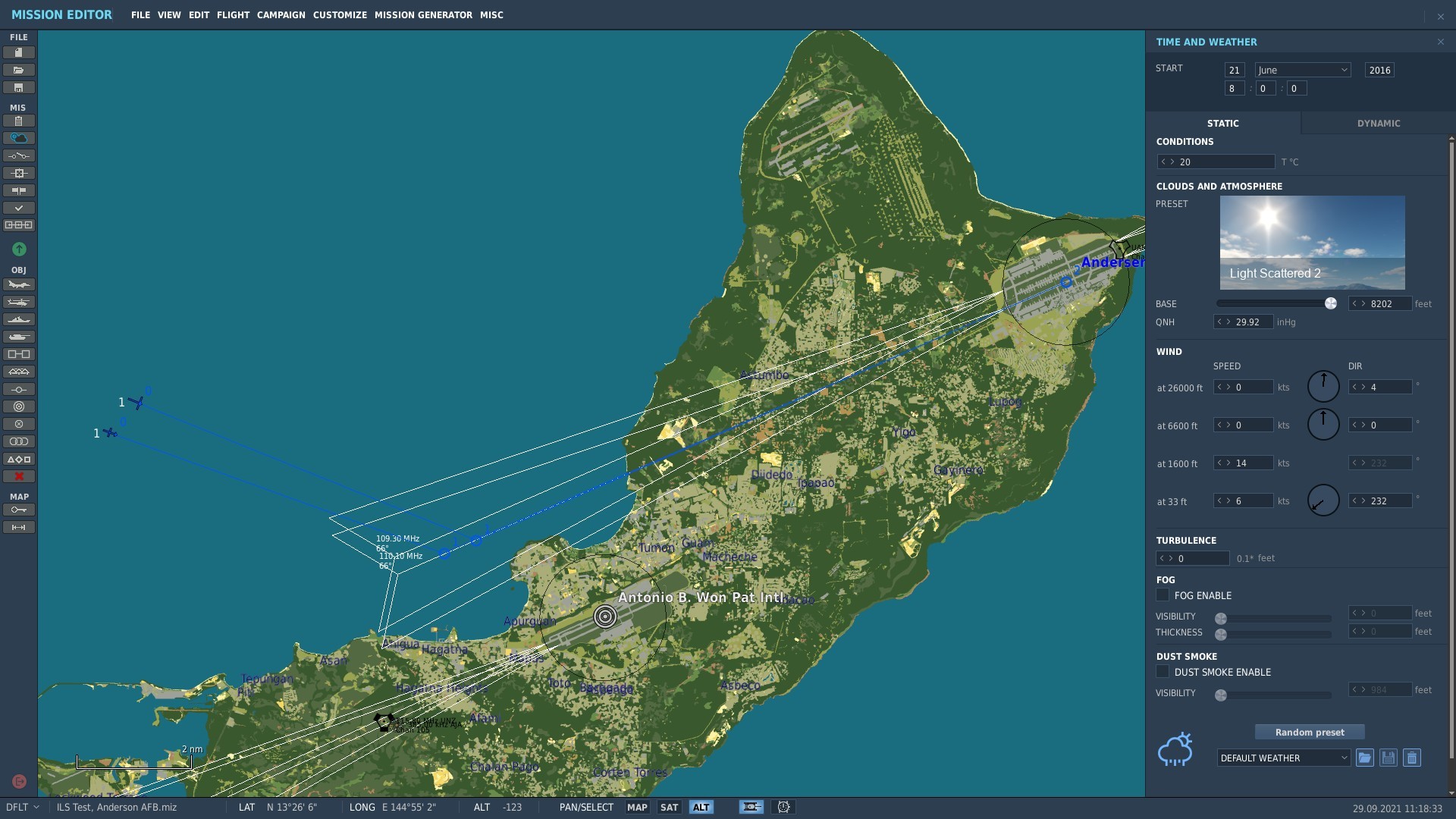
DCS 2.x.x has issues with moderate 1-5 knot headwinds for the last few years (haven't tested the recent changes to ATC/ILS sync). AFAIK DCS ATC doesn't handle multiple (Left/Right) runways yet (or does so poorly) and though the extra beacons/frequencies have been added to the maps, missions need to tailored for each airport i.e. RWY 06L ILS didn't transmit with a 6 knot headwind and ATC doesn't call out 06 Left, etc. However I didn't have an issue with RWY 06R and a 6 knot headwind from 58°T, ... did you allow for the fact that the ME uses the wind direction towards a bearing and check with ATC which direction was active There did however seem to be an issue with the Anderson ILS's for the 24 runways when changing the wind direction, as although ATC switched direction, neither ILS 24L or 24R became active. Tested in DCS Open Beta 2.7.6.13133 using A-10C and F-16C
-
need track replay TACAN Distance Meter on HSI freezing up
Ramsay replied to Ready's topic in Bugs and Problems
Your report matches these previous reports from 2018 where ED's TACAN receivers would intermittently freeze after 40 minutes in the F/A-18C, F-5E and A-10C. I haven't experienced TACAN freezes recently but have been using TACAN to line up on final, etc. rather than navigation. -
The Anton in common with most Axis aircraft uses a mother / daughter compass system, with the mother/master compass positioned in the fuselage away from sources of electrical/magnetic interference. The Mutterkompass can be a magnetic or gyro compass with electrical signals used to drive one or several remote daughter readouts. This is the best source I've found so far for it's operation https://sites.ph9.com/RemcoCaspers617/upload/editor/files/Patin remote compass.pdf I'm not sure it's modelled correctly in DCS as, AFAIK the Mutterkompass is gimbaled and will remain in the horizontal plane up to a max. 25° but in DCS shows a large error while stationary on the runway (how would a pilot check the compass heading before takeoff ?).
-
I don't recall DCS's exact magnetic declination model but it uses declination tables, using the A-10C's MFD position page allows the in game MagVar for a particular place/time to be read to 1 decimal place. Although @Nealius gets the sign of the declination wrong • Magnetic = True - MagVar i.e. 299°M = 305°T - ( +6°E) his post is accurate in what is observed in the DCS Anton.
-
In DCS the aircraft needs to be level for the compass to read accurately (not sure what is being modelled). Tested using the Dora but the Anton is likely the same i.e. screen shots show the same "wrong" compass headings at Senaki in Chuck's Guide. See this post for additional detail
-
Correct, I'm not sure what is being modelled but • flying West --> East (95°T), pitching up will cause the compass reading to increase i.e. 90°M --> 120°M • flying East --> West (275°T), pitching up will cause the compass reading to decrease i.e. 270°M --> 240°M Pitching down has the opposite effect but it's magnitude seems more dependent on how aggressive the manoeuvre was. Flying North or South (005°T/185°T), the effect seemed reduced provided the heading was already close to magnetic North/South Tested at Senaki 2016, using Fw 190 D-9, A-10C measures MagVar = +6.6°E, DCS Open Beta 2.7.6.13133
-
This covers the main points using TPOD generated TOO target points.
-
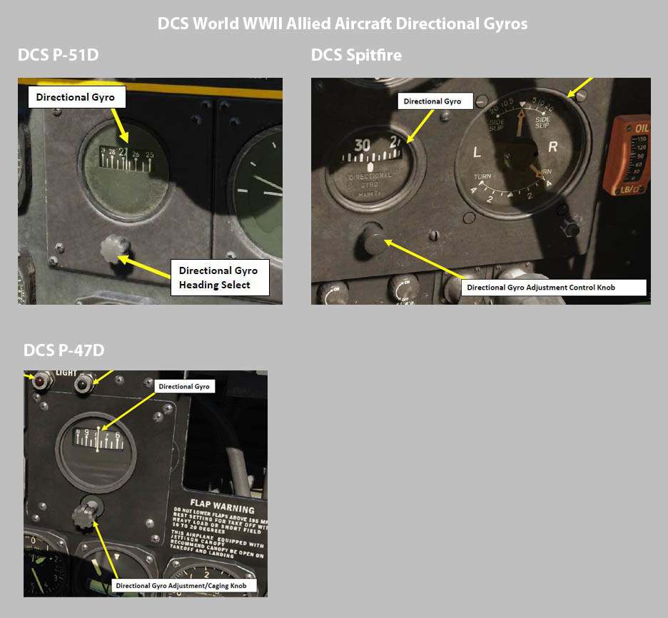
Not sure what you mean, the operation of other allied warbird DGI's are the same with the scale increasing to the left, only the DGI scale of the Early Access Mosquito is different. Do you have an example of a WWII DGI that rotates in the direction you'd "expect" ?


.png.59a64bca7a022f7916c7c8a39b7e7634.png)