Search the Community
Showing results for tags 'model'.
Found 17 results
-
Hi everyone, While the Kh-25MR appears fine prior to launch, after launch it transforms to appear as a Kh-25MP/MPU. It looks like line 570 of CoreMods\aircraft\AircraftWeaponPack\kh25_29_family.lua is to blame, "model = X-25MP" should instead be set to X-25MR and changing this line to be as such fixes the issue.
-
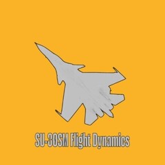
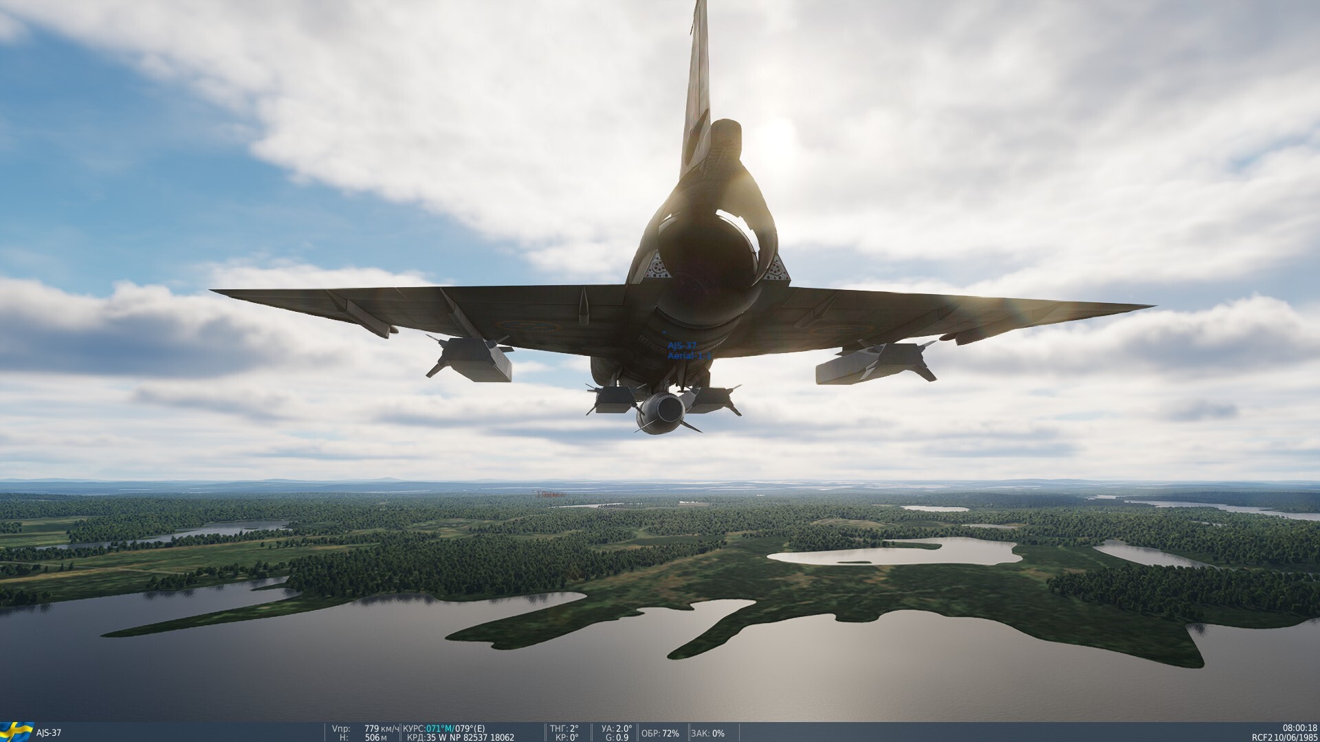
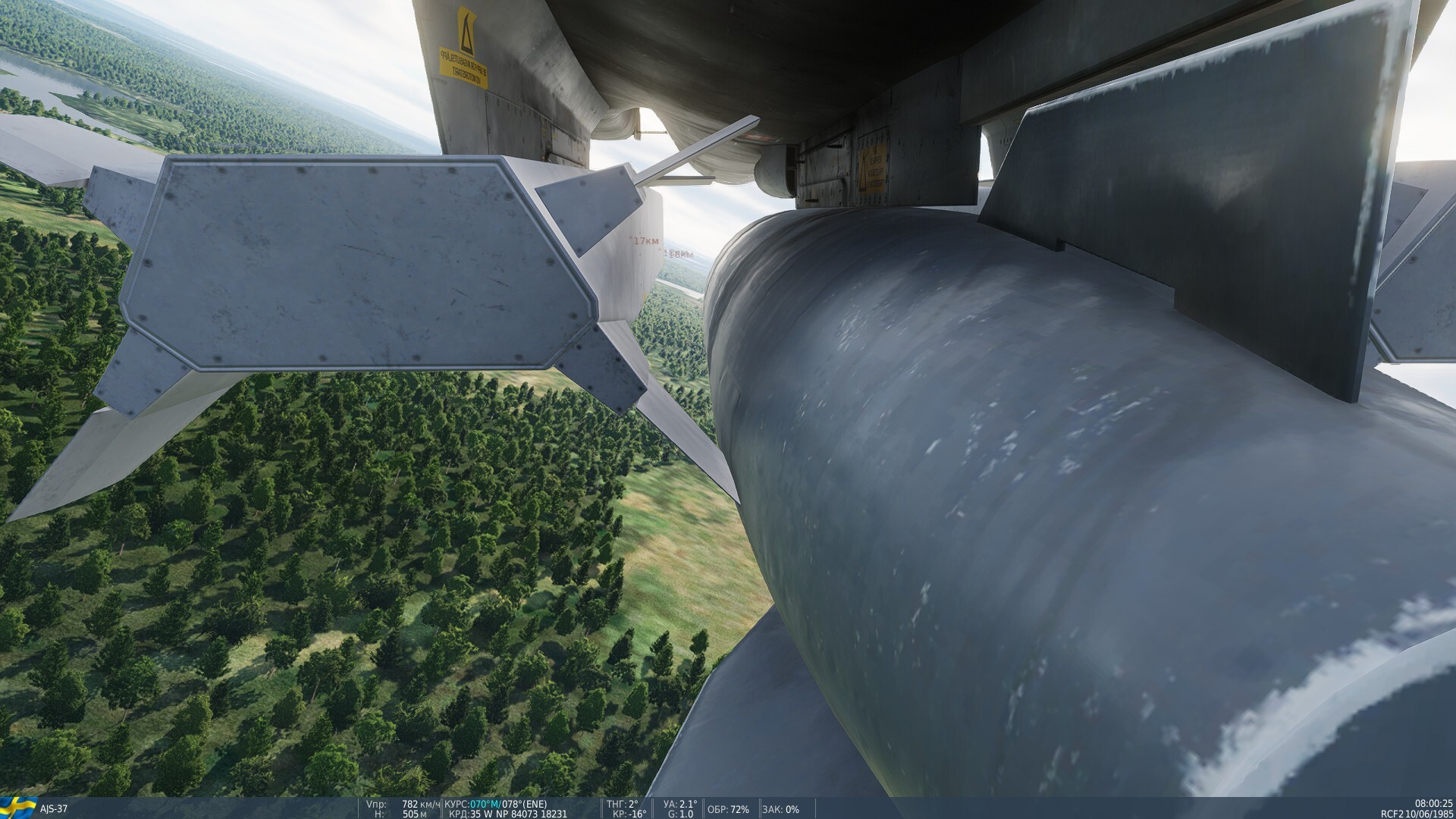
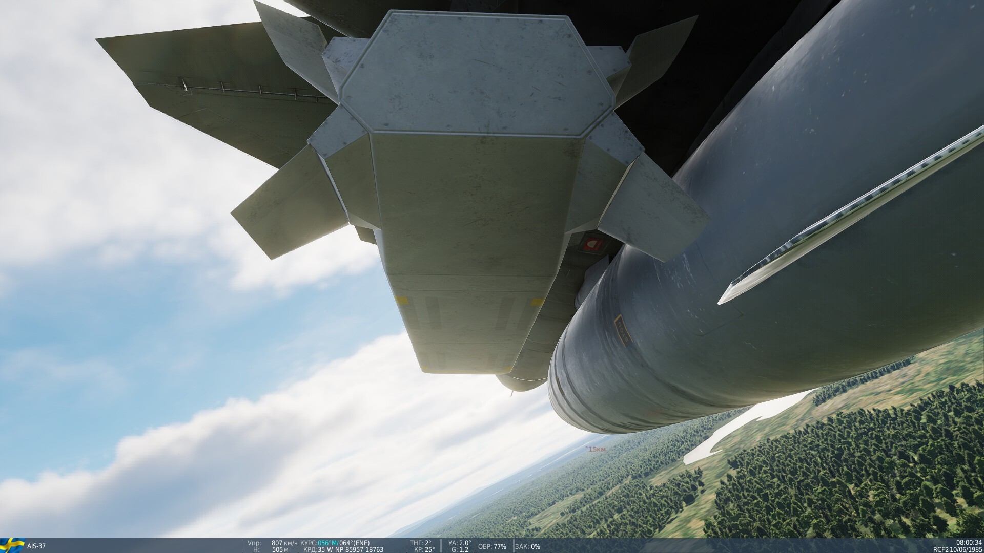
Hello. The bomb model is "mated" with the fuel tank.

-
Hello! I am Widow, and me and my development team are working to bring an A-7D Corsair II Mod to DCS. The model to this plane is nowhere near completion but here are some small snippets of what we have done, our goal is to make the best Standalone A-7D Corsair II mod that we can, If you would like to support us and our journey to creating the A-7D for DCS go ahead and join our server down below! Join our Discord community to get exclusive development updates, behind-the-scenes looks, A-7D discussions, and more. [https://discord.gg/PAH7HchW]
-
 Hi everyone, In the most recent newsletter, all of the Mogami's turrets appear to feature rangefinders - IRL, these were only present on the No. 3 and 4 turrets (though the No. 4 and 5 turrets were deleted upon conversion to an aviation cruiser, which I believe is the fit DCS is depicting - it is accurate for 1944). These blueprints are of Suyuza, but depicts pre-1943 AA conversion. The configuration forward of the stern (and the 3 forward turrets) should be identical to Mogami. Source
 -
Fairly often there is a row over the damage model, and most often it ends with confusion because as users, the best we can get are the misleading graphics for damage from the outside, and a very simplified (doesn't catch nearly everything) debrief window that's only available to singleplayer. And aside from that, a small chat window that just says "Aircraft damage/destroyed" on the right side of the screen. It would benefit a lot of discussion and potential bug-finding if a tool such as featured here in Nineline's video we're available and open to OpenBeta users.
-
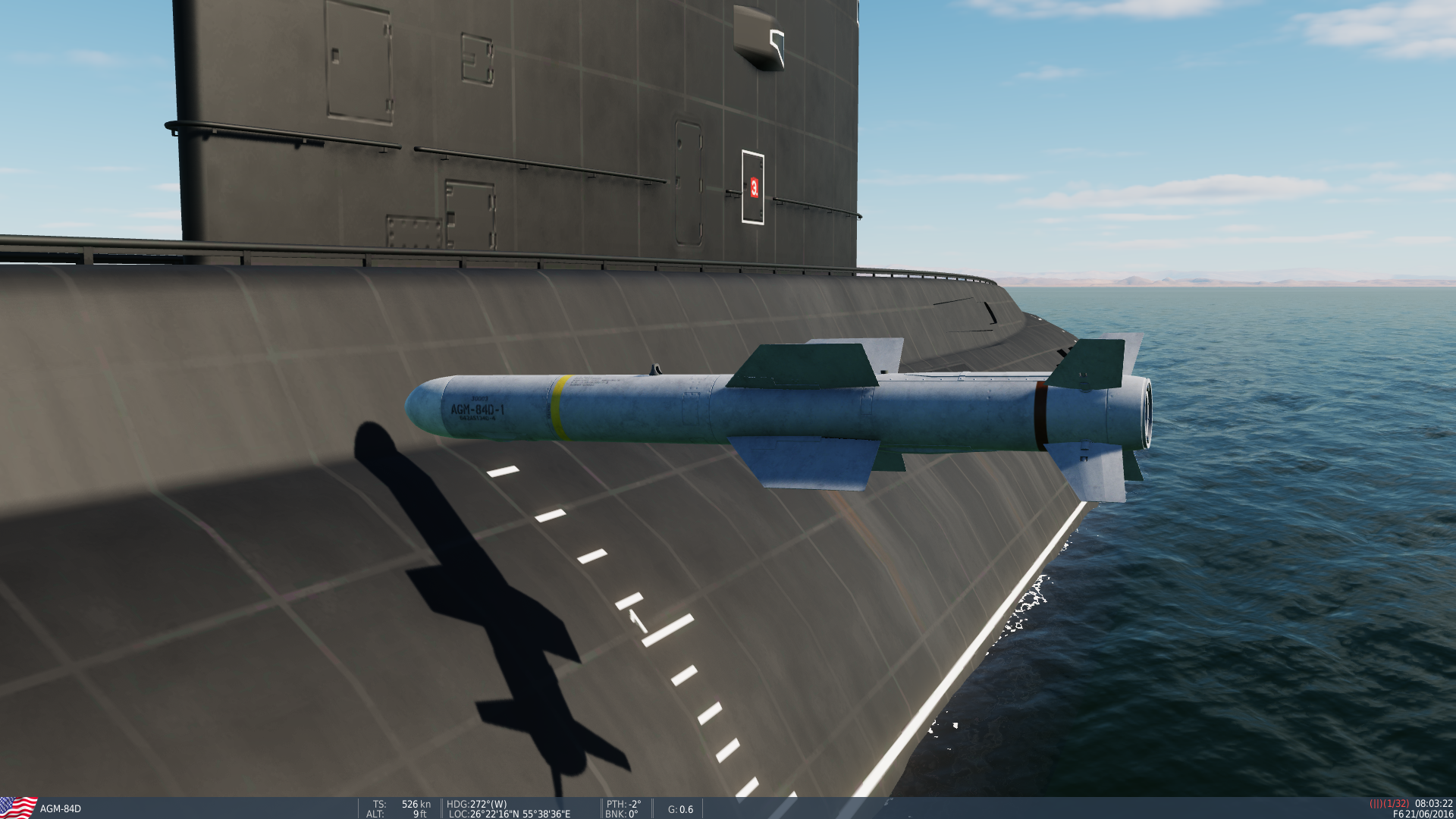
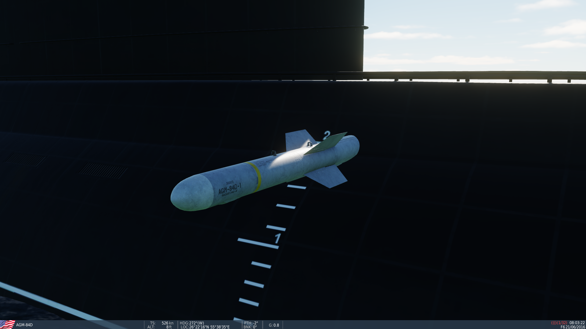
 Someone informed me that they fired RB-15s onto a sub and the missile went right through and do no damage, I made a quick test to try and recreate it but I used a hornet with harpoons instead. Similar result. The harpoon goes right through as seen in these screenshots. I'll provide my .miz file i used for the test and a track file as well. I did another test but using a AGM-65F as well and similar result but the MAV still goes right through and explodes as it hits the water where the sub is and does splash damage instead. If memory serves me right a single AGM-65F should sink a submarine (Improved Kilo class) in 1 hit. Sub Harpoon Test.miz Submarine Harpoon.trk
-
 TL;DR first: The P-51 does not have it's fuel vapor line simulated in DCS. This could have a noticeable affect on how much fuel is recaptured into the fuel tank, as it could be as much as 10 gallons an hour. In close conjunction, the fuselage tank vent line (that the vapor return line feeds into) does not appear to be modeled, quite literally. Track: P-51 Fuel Vapor Return Check.trk I'm going to split this into two different parts. One for the fuel return line, and one for the fuselage tank vent. THE FUEL RETURN LINE: 1) THE ISSUE The DCS P-51 currently does not simulate fuel being returned to the fuel tanks from the carburetor. You can check this yourself by loading the P-51 with full fuel, and run on the left tank until it is empty. Then run and drain the fuselage tank next, followed by the right wing tank. You can check if any fuel was fed into the left or the fuselage tank by checking the gauges, and setting the fuel tank selector to either the left for auxillary tanks. You'll notice that no fuel will feed, the tanks are still empty. This is what's included in my track replay, linked above. 2) THE INFORMATION The fuel vapor return passes excess fuel from the carbureator back to a fuel tank. It is widely touted that this excess fuel was routed back to the left wing tank. However, starting halfway through P-51D-15 production, this line was redirected to instead feed into the fuselage tank behind the pilot, using the same opening as the fuselage tank vent line. Photos: The following two photos were taken from the Pilot Training Manual, AAF Manual 51-127-5, dated 15 August 1945, from page 20 and 22 respectively: Now here we have a maintenance manual (AN 01-60JE-2, 13-Feb-1948 Section IV, Para 14-15) stating the same thing, with some more detail. In addition, a representative drawing showing the placement and path of the fuel lines: Now, how is this dated to the P-51D-15? If you look at the schematics for the Mustang, you'll see assemblies for building the pipes to link the carbureator to the fuselage tank. Here you'll see this fuel vapor return line, returning fuel to the fuselage cell vent. On the bottom left, it reads used on P-51D Airplanes AAF 44-15253 & Subs[equent] also on AAF 44-11953 and Subs[equent]. The P-51D serial number is a D-15 airplane, halfway through their production run. So it's clear that when referring to the Californian Mustangs, it's specifically pointing out the middle of the P-51D-15 variants, when the vapor line change was implemented. However in this source, it seems that some Dallas-built Mustangs serial numbers are excluded or missed. I think we can assume though that the change occured similarly as in Cali, on the D-15s. 3) THE FIX At a rate at 10 gallons per hour or less, fuel should be fed back into the fuselage tank. For simplicity sake, it could be a generalized 7 gallons per hour, as DCS pilots will constantly change their engine settings between economic settings and military power, or even WEP. THE FUSELAGE TANK VENT LINE: 1) THE ISSUE In DCS, this fuel vent line is not in the 3D model at all 2) THE INFORMATION This was a tube that vented the fuselage tank, and gave air a place to enter the tank to stabilize the pressure as fuel was consumed. Additionally, with the fuel vapor return tube directly connected to it at the point that the joint where the vent tube met the tank, this would be the pathway that excess fuel would be leaked overboard and outside the aircraft, in the event the fuselage tank is full. Schematic drawings: Exerpts from the E&M Manual: 3) THE FIX The vent line isn't even represented visually in the cockpit, but it's in a very hard to see location so it's not that pressing. However, it is also not even seen from the outside, specifically the outlet port, that was located at the bottom of the USAAF insignia on the right side. It is an external identifying mark of Mustangs with the fuselage tank installed. And in addition, it is also where fuel will vent outside the aircraft, in the event the fuselage tank is already full, and getting fed by the fuel return line from the carburator.
 -
Hi everyone, I've noticed some minor model issues with 4.5" Mark 6 naval gun, common to all of the Leander-class ships and the 2 Condell-class ships introduced in the new asset pack. Starting with the gun rounds, the 4.5" Mark 6 naval gun, as the name suggests, has a calibre of 4.5 inches (114.3 mm), at the moment however it's firing 130 mm rounds (presumably copied from the Slava class' AK-130). The real gun should have HE, SAP, AA (not sure if it has a timed or proximity fuse) and possibly, illumination. Secondly, there's the 3D model of the turret itself, which looks a fair bit off; the gunhouse is largely the correct shape (though roof doesn't look as sloped), but the main problem are the barrels, which are way out of proportion and serve to make the turret look more cartoony IMO:
-
Hi everyone, A fairly minor issue that's as old as DCS: every unit with "Ural-375..." in its name (be it current or in-development assets) are not actually Ural 375s, they are in fact Ural 4320s. While the 2 are very similar externally, there is at least one obvious difference, which is by far the easiest way to tell them apart - the grille; the Ural 4320 has a grille with much more prominent vertical bars compared to the 375. The vertical bars also have a slight angle to them roughly 1/3 the way down from the top, whereas the 375 looks to be pretty much completely flat. Here's a comparison of what the 2 look like in reality: Ural 375D: Ural 4320: Note the significantly more prominent and thicker vertical bars on the grille on the 4320 as opposed to the 375 and also the slight angle to them ~1/3 the way down from the top. And here are the current models present in game: Truck Ural-375: Truck Ural-375 Mobile C2: SPAAA ZU-23 Mounted Ural 375: As you can see, all 3 clearly resemble Ural 4320s - not Ural 375s. To top it off, the unit "Truck Ural-4320T" has an identical cab with an identical grille seen in these models. This also applies to the 2 WIP Ural 375 trucks, showcased in this newsletter from 2019: While the angle of these 2 don't give us a good view of the grille, it's still fairly clear that these are actually Ural 4320s as opposed to 375s (the more prominent vertical bars can just be seen, and they have the angle to them). When these WIP models do finally get released it would be better to have them replace "Truck Ural-4320" and not "Truck Ural-375" as that too is an outdated LOMAC-era legacy model.
-
Noticed that the trim gauge does not have its glass cover during some retexturing for the gauge face glass. This pink appearance was a solid color fill on id_13_D_FILTR, which doesn't bring anything up on the trim gauge. Also noticeable by looking at the default/unedited gauges at a sharp angle. Comparison between the default RPM (U/min) gauge at an angle and the trim gauge at an angle:
-
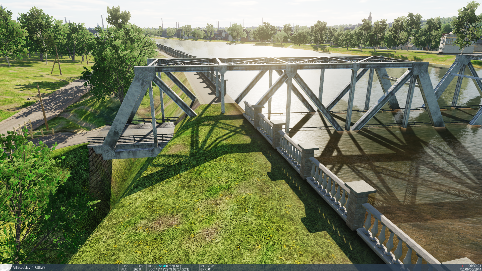
This bridge on the North side of L'île Saint-Germain located at N48°49'27" E2°14'55" appears to be submerged in the water. On the North end, the bridge clips through the terrain. On both ends, the terrain has an odd looking trench. The smaller bridge on the south side of the island also has those trenches. Additionally, the bridge seen in game is a truss bridge, but Wikipedia has a historic photograph which does not include the steel superstructure. I may be mistaken about this - I'm not sure if this photo is the longer or shorter bridge.
-
Simply, is it possible to add an invisible model piece that covers a large section of the nose of the aircraft, similar as is done with bort codes? This would be a place for livery creators to easily add things such as nose art, and have it be easily disabled within DCS via rearming menu to switch between a livery with nose art, or a generic squadron livery on the fly. This would save massive storage for liveries, as this would essentially merge two liveries into one. While in the current system, one has to create a decorated livery and a generic squadron livery separately, with a system similar to bort codes (but for nose art) this would allow the livery to switch between the two, but within a single livery, saving space in DCS and making usability faster, and livery creation easier.
-

reported Canopy Glass is Flickering During Head/Zoom Movement
razo+r posted a topic in Bugs and Problems
The external part of the glass is flickering. -
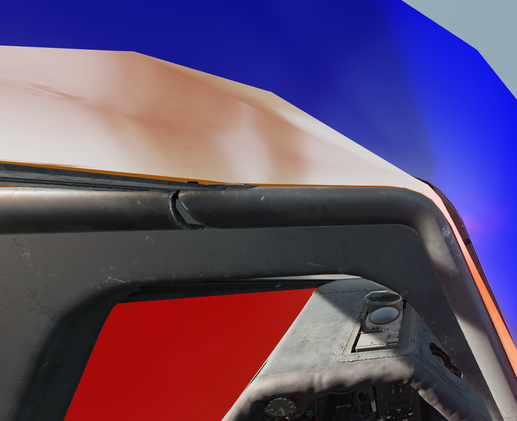
There appears to be some sort of visibility bug with the interior canopy glass material FW_190_GLASS_INT. All textures, to include the diffuse, and the roughmet and probably the glass ('14' in the description.lua) will flicker in visibility when head or zoom movement occurs. Here is a video, after I gave each material's diffuse texture a color (seen in the quotations in the description.lua at the end). If you remove the diffuse texture (set it to empty) so you only show the the glass texture ('14') for FW_190_PLEXGLASS_extr, it flickers with its parent material FW_190_GLASS_INT as well. This does not appear to be due to the interior and exterior planes being positionally coincididal (overlapping), as you can still make out the two if you move the camera inside the glass pane. The glass hue texture (14), which is used on both inside and outside materials: The FW_190_GLASS_INT in red, and the FW_190_PLEXGLASS_extr in blue. Both are visibly separated between inside and outside materials: While I'm using the ModelViewer here since I have more control, there's been folks reporting it occuring during gameplay.
-
Hello, help me find a script to add a missile guidance TV screen to a custom cockpit, or tell me how it can be implemented э. Здравствуйте, помогите пожалуйста найти скрипт для реализации в кастомной кабине в игре Lock on flamming cliffs 2 этого ТВ экрана для наведения ракеты таких как Х-29Т или Х-29ТЕ, если не скрипт, то подскажите как этот экран можно реализовать
-
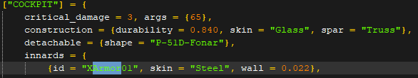
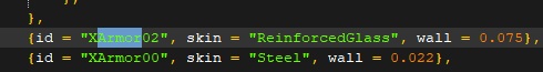
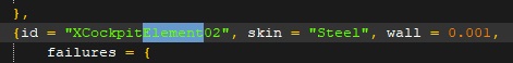
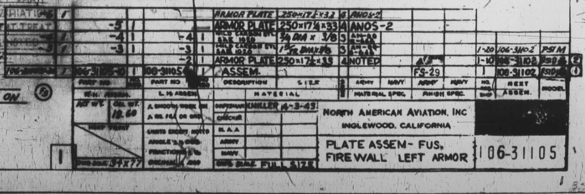
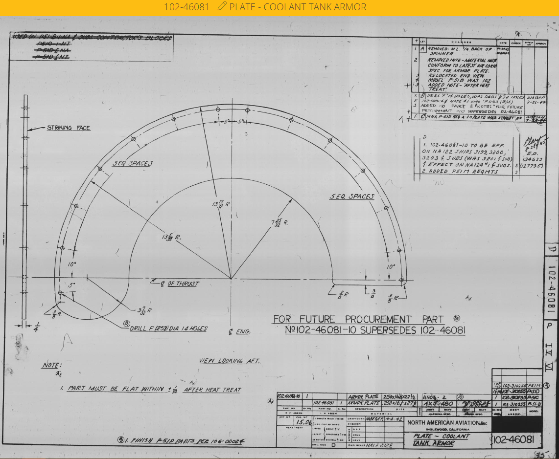
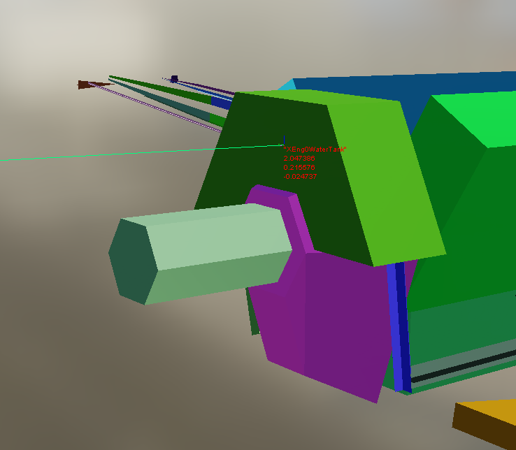
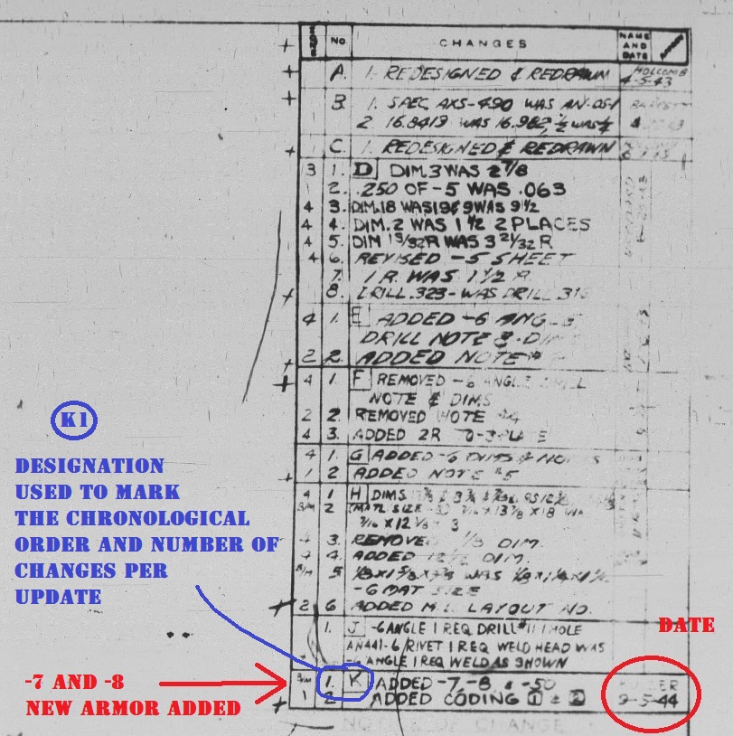
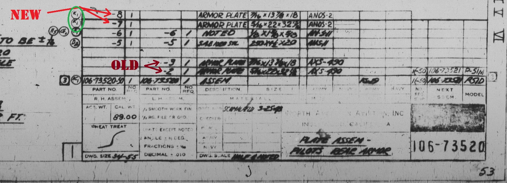
12/16/22 Preface: In this Friday's OpenBeta update, the easy coding fixes have been added for the P-51, 190s, Spitfire, 109, and 47. However, the Mosquito has been missed. Additionally, the armor plates that are missing from DCS entirely haven't yet been included. Items that were fixed in the 12/16 OpenBeta update will be highlighted in green, and marked with the update date. TL;DR: Many warbirds have incorrect armor values, or are missing armor. If you open the x-ray.edm in the Modelviewer, and the individual aircraft's Lua, you can see the IDs from the Modelviewer and see what those objects' properties are. Please click on the photos here, as while I've minimized them in this post so it doesn't get cluttered, but if you click on them you will see them in better resolution. The P-51D (INCORRECT): [FIXED: DEC 16, 2022]The headrest and seat back armor (aka XArmor01 and XArmor00) - If we open Aircorps Library and look at the drawings for the late P-51D, like ours, we will see that these are two pieces of armor welded together. The headrest being 7/16", or 11mm...and the seat back being 5/16", or 8mm thick. Meanwhile in DCS, it is given a thickness of 22mm! For both plates! Almost three times the value of most of the area of the armor. I have an idea on how this value came to be, but I'll drop it into the spoiler below: [FIXED: DEC 16, 2022]The armored glass (aka XArmor02) - In DCS, it is given a thickness of 75mm. Using the schematics from Aircorps Library, we can again see that it is 1.5" thick, or 38mm. [FIXED: DEC 16, 2022]The instrument panel (aka XCockpitElement02) - In DCS, this is given a thickness of just 1mm! In truth, the instrument panel is a part that's for once, thicker in truth, coming out to 0.128", or 3.25mm. [FIXED: DEC 16, 2022]The firewall (aka XArmor03) - This is given a value of 12mm in DCS, or just a scratch under 1/2". For our 51D, it appears that a more possible value would've been 1/4", or 6.35mm. The P-51D (MISSING): The coolant header tank armor - This is a piece of armor that has been missing from the Mustang's damage model. It is 1/4" thick, or 6.35mm, and lies just forward of the coolant header tank within the engine nacelle, between the coolant header tank and the spinner. In summary for the P-51: -[FIXED: DEC 16, 2022]Change XArmor00 from 0.022 to 0.008 -[FIXED: DEC 16, 2022]Change XArmor01 from 0.022 to 0.011 -[FIXED: DEC 16, 2022]Change XArmor02 from 0.075 to 0.038 -[FIXED: DEC 16, 2022]Change XArmor03 from 0.012 to 0.00635 -[FIXED: DEC 16, 2022]Change XCockpitElement02 from 0.001 to 0.00325 -Add coolant header tank armor. Steel, 0.00635
- 29 replies
-
- 10
-

-
- protection
- dcs
- (and 17 more)
-
 Я скачал скрипт, засунул его в Макс 12, делал все по инструкции, указываю путь к папке Shapes а модельки не открывается, приложу видео для просмотра проблемы более понятно, заранее спасибо большое за помощь VID_20250110_190403_802.mp4 I downloaded the script, put it in Max 12, did everything according to the instructions, I specify the path to the Shapes folder, but the models do not open, I will attach a video to view the problem more clearly, thank you very much in advance for

(4).png.791a9d8dcb3379550899eca266da2a38.png)
(3).png.c2f1d0cc20837a86c2e2a22572c5acba.png)
(2).png.b5dd1aa7e809257a4ae2114ca2e42272.png)
(1).png.f2b5ca55b9b7654a8bfab4fdfa43b286.png)
.png.8d6d55d1ef2bf71c2438908c803a0793.png)
(5).jpg.fb3d54d31d8c034de2371d9cc07218f7.jpg)

.png.21a204103c77a0c43197a9527a1c9657.png)