
Rongor
-
Posts
1595 -
Joined
-
Last visited
-
Days Won
3
Content Type
Profiles
Forums
Events
Everything posted by Rongor
-
how would you know its on? Is there any indication? Mine looks dead.
-
Cant find any controls setting to switch it on.
-
any module is complete by itself. If you want to fly the A-10C II, you only need to install the A-10C II
-

How does airliners appear on Hornet's sensors IRL?
Rongor replied to Darcaem's topic in DCS: F/A-18C
Any IFF challenge wouldn't receive any response. Civilian aircraft don't have Mode 4 transponders. If they appear as friendly via datalink, some AWACS or GCI might've designated these contacts as friendly, relying on other sources. If there is no such controlling instance, then any appearance as friendly is realistically impossible. -
considering the terrain elevation in the example above, this could simply be parallax error
-
DTOT-fed Required speed in HUD might have issues
Rongor replied to Rongor's topic in Bugs and Problems
The R-speed didn't change. And btw -:07 actually means I am already 7 seconds late, so reducing speed further makes no sense. -
DTOT-fed Required speed in HUD might have issues
Rongor replied to Rongor's topic in Bugs and Problems
-
Of course you can. Don't think you should though.
-
DTOT-fed Required speed in HUD might have issues
Rongor replied to Rongor's topic in Bugs and Problems
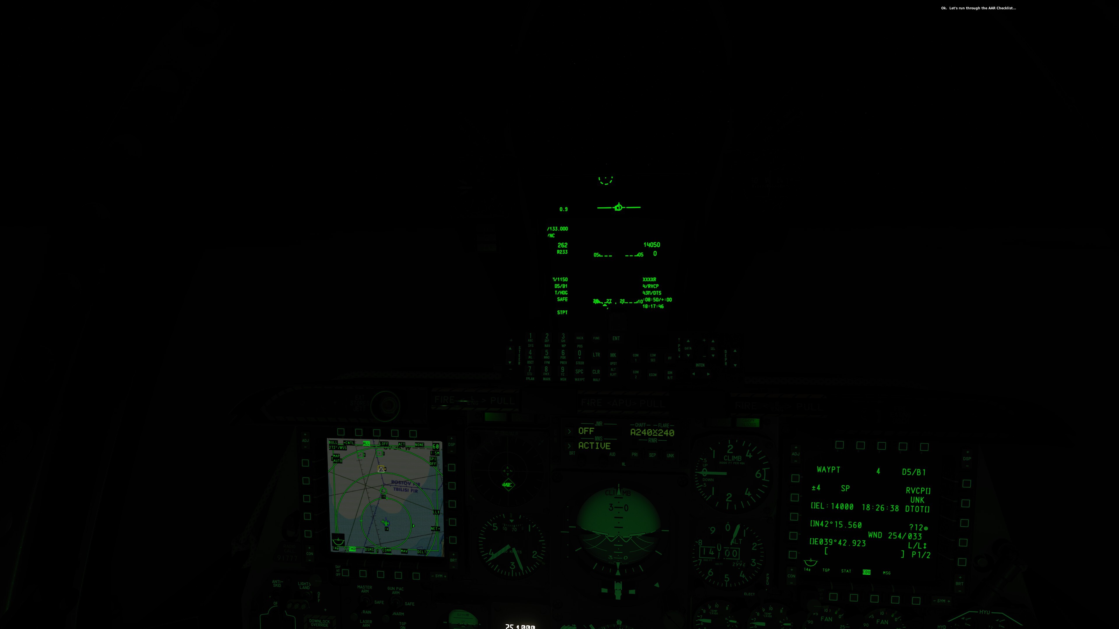
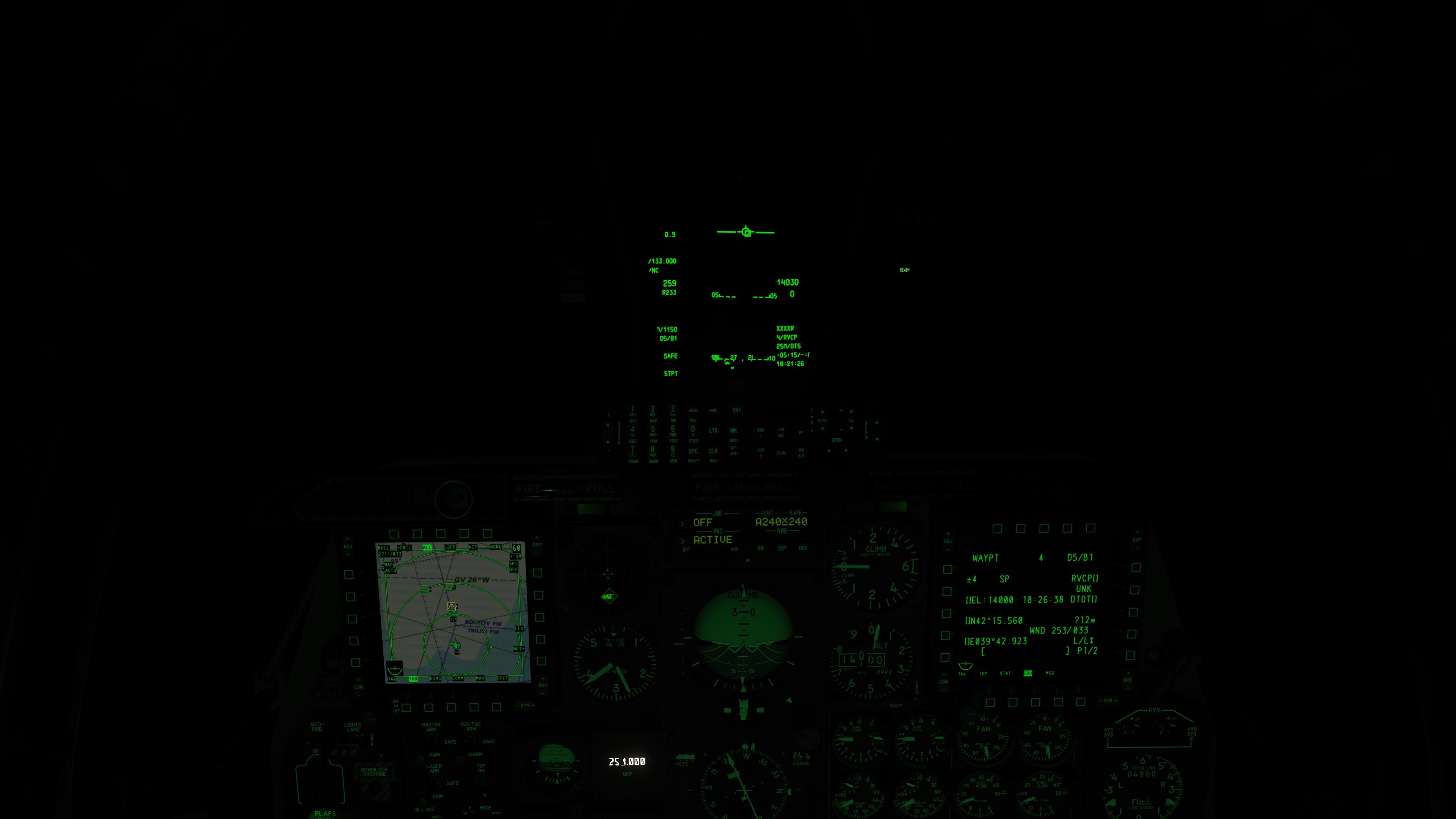
I think you still don't get it (please don't take it the wrong way, I appreciate you participating here) Flying the R-speed in the example above wouldn't have prevented arriving 7 seconds late. It would only have gotten me even more late. The 195 kts did keep me right on time. (7 seconds is nothing at this distance, basically equals right on time). Reducing to R-speed did increase the negative delta rapidly. Just do the math: 195 : 170 = 1.147 13:25 = 805 seconds 1.147 * 805 seconds = 923 seconds (15:23) Flying R-speed would have taken me 15 minutes 23 seconds. I would have arrived at 18:28:35, more than 2 minutes after DTOT. Here is another example which might make it more visible, because two pics this time, I fly constant speed of around 260 keeping the delta at zero, while the R speed tells me to do 233. 1st pic at 43 Nm distance, 2nd at 25 NM distance almost 4 minutes between these pics. The R-speed doesn't make any sense here.
-
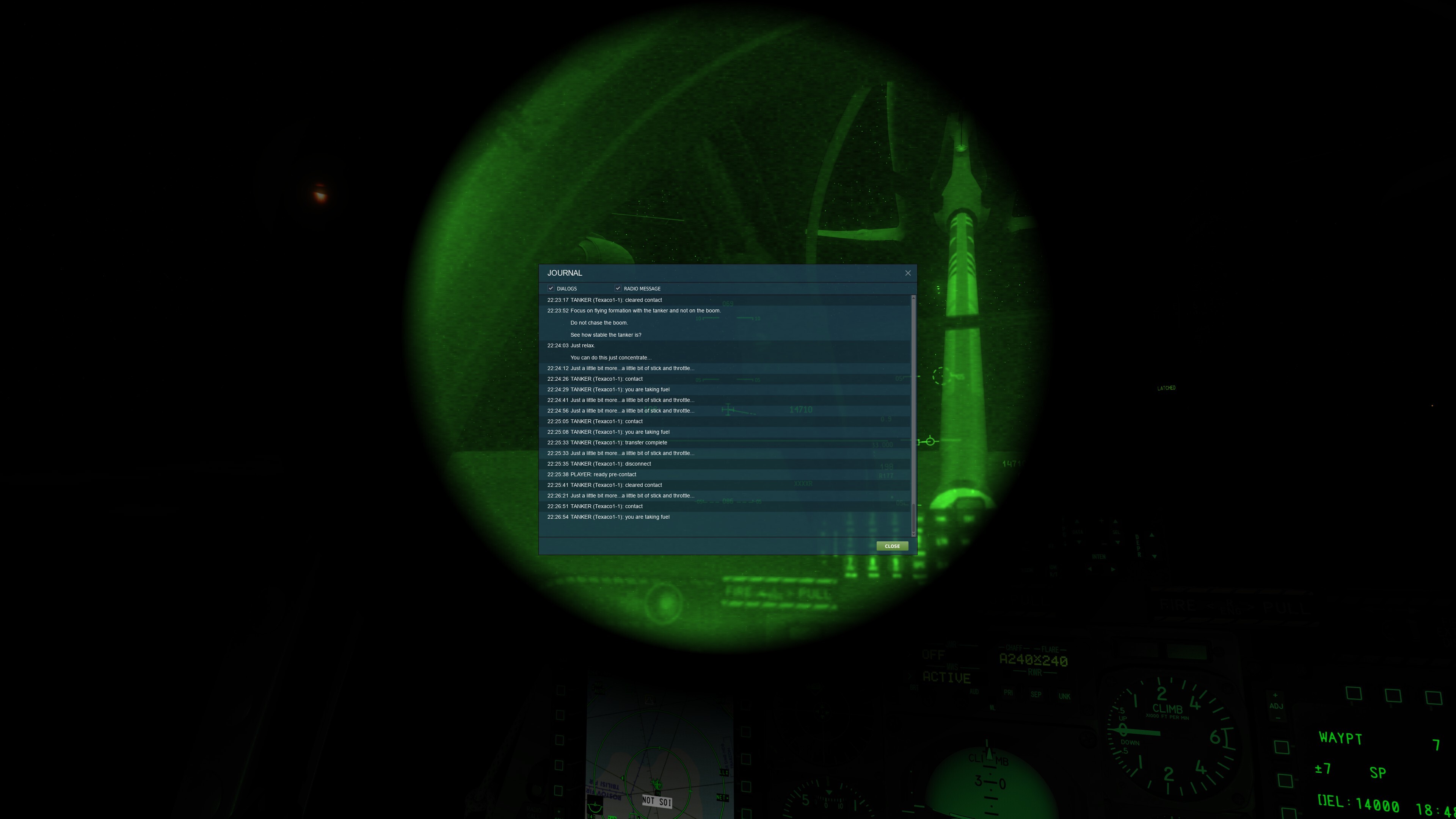
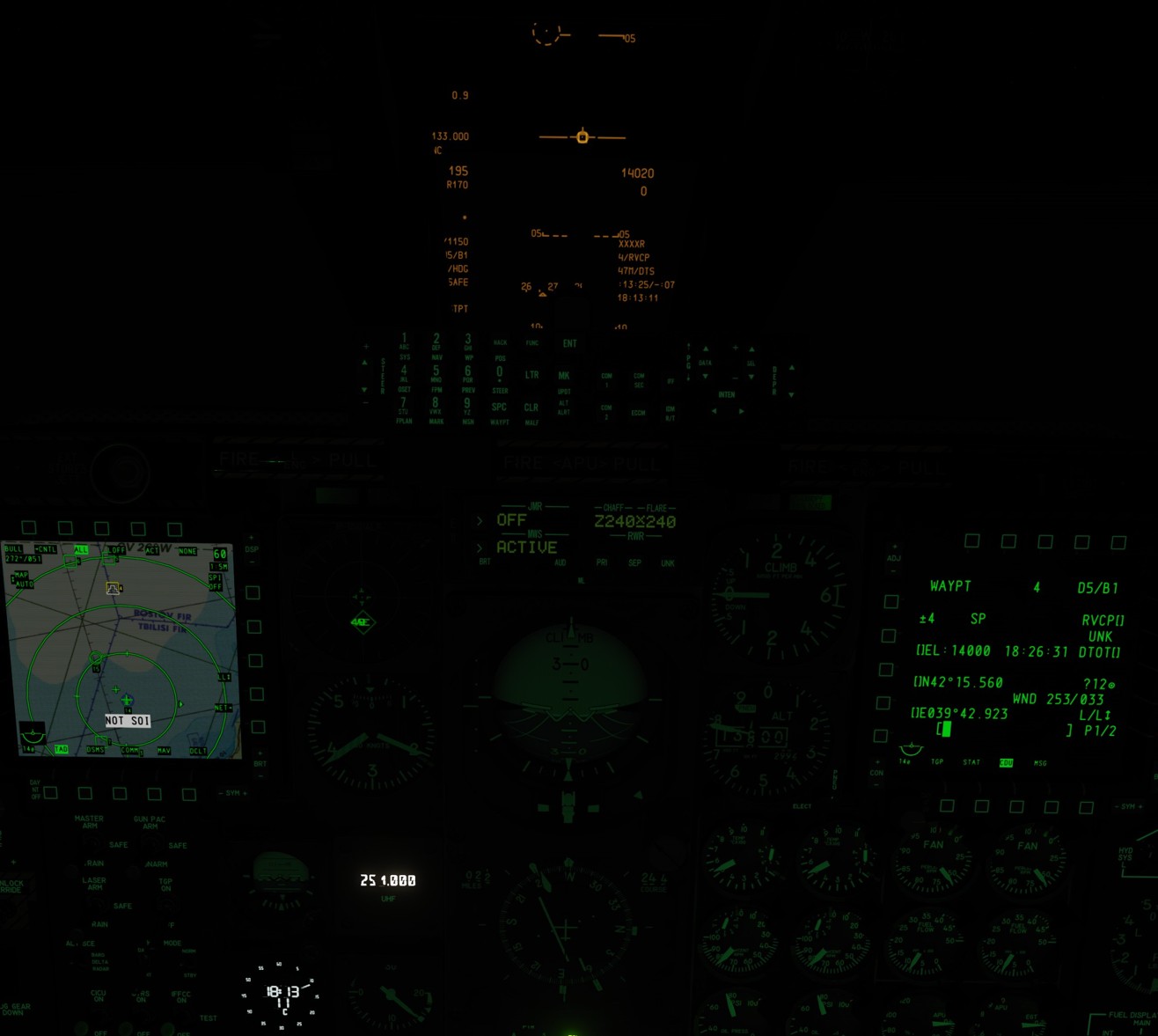
Tried it again today, again allegedly missed the rendezvous. As you can see in my HUD, I should be right on time to arrive at WP4 at +00 at the DTOT 18.26 in 2 minutes and 31 seconds. [Btw if you look at the R speed on the left side of the HUD, there seems to be some issue with the DTOT based R-speed calculation. I'd say it might not be connected to the issue here, as I would arrive even later when reducing to R231. Still a problem which I'll report in the A-10C subforum] I accepted the Q- in advance and have arrived at the tanker, between WP6 and WP7. Now I face the problem that the examiner doesn't seem to acknowledge my successful connects, He just doesn't comment anything besides the "little bit more stick and throttle" advice. Just in case this might be a trigger thing: I kind of bypassed WP5 and WP6, since before arriving at WP5 the examiner told me I should follow the tanker into the turn while it was turning at WP5 ahead of me, so since I was already "too late" I shortcutted into a dog pursuit directly aiming at the tanker, yet remaining on 14000 ft. So I am afraid this mission might fail by resulting in a U-rating. While I am actually doing perfectly After 9 successful connects (without examiner commenting) he told me "enough for the day" when we arrived at WP7, RTB to Kobuleti went without issue. The IFR CAT-III approach was pretty cool - although the rwy 25 ILS seems to have issues) As expected I received a U-rating. Still after ending the mission the score was 80, so I am free to continue with AATQ3
-
While the initial developer still seems to be AWOL, may I ask how it is possible we still receive patches on the map? Can we expect to see the map developed further by ED or who is now responsible? Is there a roadmap for "completion" or is this entire SA map project rather sidelined but occasionally receiving small adjustments?
-
You won't need 588 GB for an update, rather for an entire installation from scratch.
-
sure? null
-
Wouldn't surprise me at all, keep in mind how suspiciously often it was included in many of ED's videos. I expect the Germany/cold war/central Europe map we already've seen in videos. Then likely some more C-130 footage, MiG-29A, added stuff to Afghanistan, Iraq, Supercarrier and the CH-47. Maybe some Pacific WW2 stuff. Beyond these its purely speculation.
-
DTOT-fed Required speed in HUD might have issues
Rongor replied to Rongor's topic in Bugs and Problems
It doesn't really make sense to slow down from 195 to a constant R170 to shave off 7 seconds deviation when I have to go for another 47 NM right? The reason I was doing 195 kts is that by experimenting for some minutes before taking the screenshot I found out that maintaining this very 195 kts speed kept me on time. -
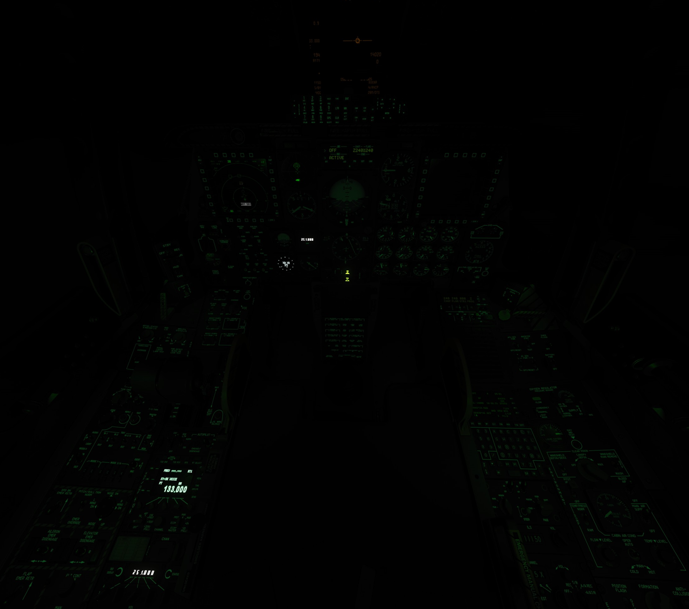
Is there any way to adjust (tone down) the brightness of the clock, the NMSP, the ARC-164's front dash frequency repeater, and on the left console the ARC-210 and ARC-164?
-
reported DTOT-fed Required speed in HUD might have issues
Rongor posted a topic in Bugs and Problems
R-speed wants me to fly 170 kts, while I am very right on time doing 195 kts.
-
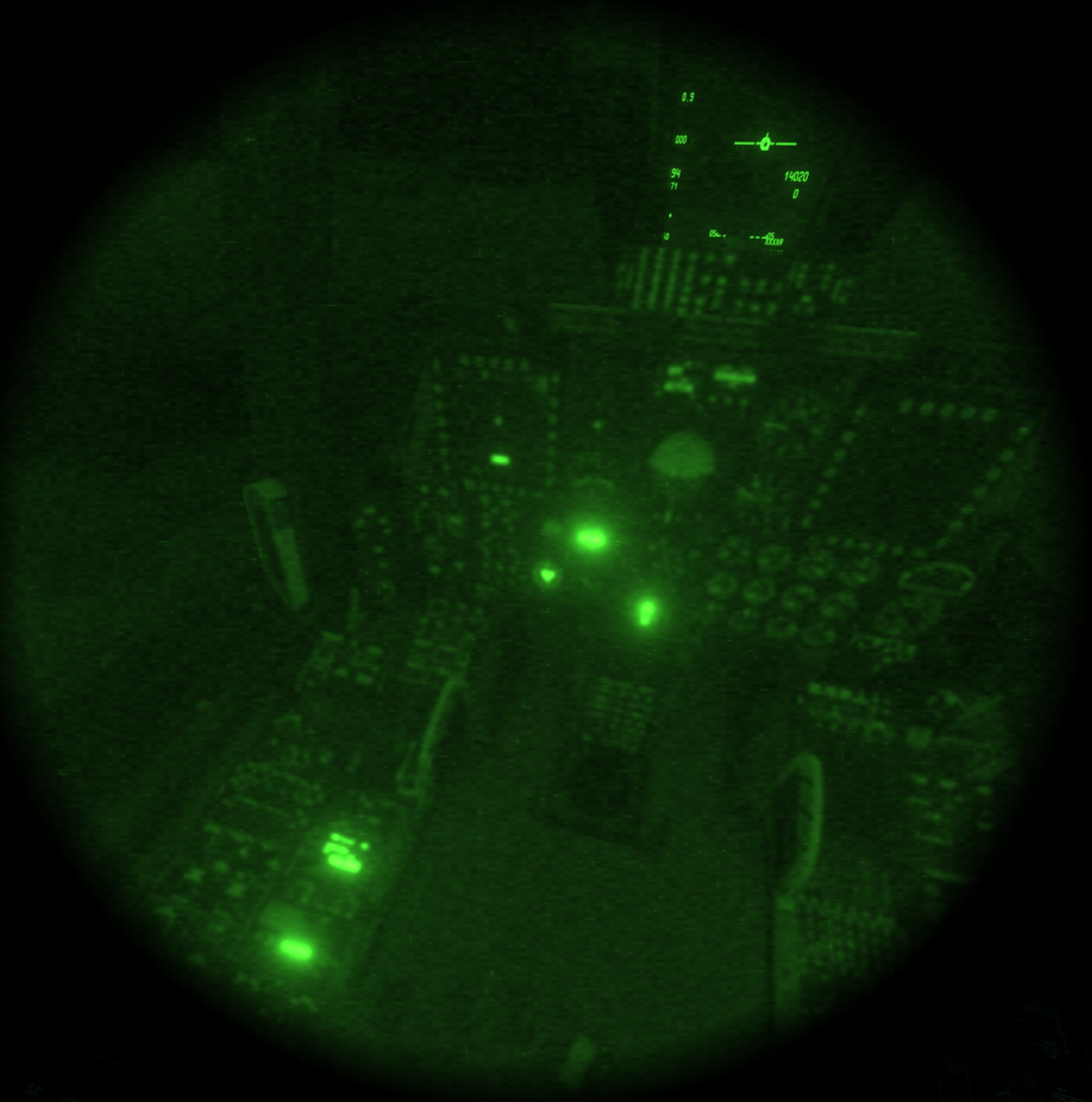
I have some problems with confusing contradictions of the Delta Rendezvous the mission claims to suppose us to follow. - Calling the tanker at the RVIP doesn't actually make it turn to arrive at the RVCP in time (RVCT) - setting TACAN to anything else than T/R doesn't give any readout, to get the tanker's bearing and range, you have to set it to T/R, not A/A as demanded by your examiner. - (this one only during the training mission) maintaining the long distance towards waypoint 4 (RVCP) had me fly inside of clouds most of the time. Getting above them at around 14200 of course triggered a Q- rating for deviation from the demanded altitude - examiner calls out friendlies from 11 o'clock at least 2 times. Unlike during the daylight mission I didn't see any of these, it was pitch black, NVG only showed stars, no aircraft, no idea how my examiner might have spotted them - we are told to fly at "appropriate speed" several times. Since we learned how to deal with DTOT during the BFT course and also keeping in mind that its mission critical to arrive right on RVCT, I flew the R-speeds correctly. This made me end up 15 NM trailing the tanker (at a slower speed than the tanker) and the examiner claiming I failed to arrive on time, while the DTOT clearly shows I am right on time. Quite frustrating, as this occurs 40 minutes into this rather long mission... situation seconds after I "failed" to be on time at the RVCP: I am 6 NM out and will arrive in 1:40, right on DTOT (deviation is less than 10 seconds). Tanker is 15 NM ahead though, 9 NM beyond the RVCP...
-
This is neither an A-10 specific topic nor is ED responsible for this project. Visit Ciribob's Discord https://discord.gg/2atSs7kT or the pinned thread here
- 1 reply
-
- 1
-

-
In many missions these 2 wingmen just get uncomfortably close. Especially with slow speeds, their simple flight model makes them shift around at almost teleporting speeds, often then jumping around directly in front of your nose in less then an aircraft's length distance, giving you headaches while landing. I had one of them crash into me during the early missions when I was rated for landing performance. This made me fail because "you damaged the aircraft". Similar issue when doing the no engine landing on the little air strip. One of these guys must have followed me until I was close to the ground, then he ejected and his aircraft crashed into my wing. "you damaged the aircraft" I understand these 2 guys might be usefule when demonstrating the benefit of the clearing turns. In all other cases, a 3rd wingman shouldn't be required and assuming we have our instructor being a single wingman for us, why not keeping him at 1000 ft (or more) distance? Right now it seems more risky than beneficial and it does in fact occasionally ruin the mission.
-
First I want to say thanks for this mission, its a good challenge to get you back into being more proficient with the CDU. Today I flew this one almost flawlessly. Only at the very first waypoint, I arrived too early. Sometimes its difficult to determine from when the 5 minutes timer is supposed to start. At the beginning of the instructor telling me the coordinates, at the time he states I have 5 minutes left or when he is done with all his advice? Besides that confusion, which cost me being on time at the first waypoint, everything else in that mission went perfectly. So as usual when everything but a single item goes well, I expected to receive a Q- rating. Instead: The last task is to navigate to Batumi by TACAN, which again confused me as I wasn't certain what kind of trigger would test me using the TACAN at all. I wasn't that far north from Batumi, I could've and would've called Batumi ATC regularly at this point to get the vectoring to the approach segment. instead I followed to the TACAN's 75° radial to enter the traffic pattern's downwind leg (as we learned to do some missions earlier) and then called Batumi tower while in the extended downwind. Did a lefthand U turn into extended final rwy at 2500 ft coming from 230 kts as usual in these missions. Instructor never complained. After landing I parked at the tanker as usual and shut down. After calling sierra delta complete, instructor was very happy with my shutdown procedure. Then it got weird: He didn't - as usual - continue with my ratings for each segment of the PO. Instead the "You failed.." message played, which we usually only get to hear when the instructor cancels the PO mid flight. Not sure if this was connected to my TACAN use (instructor wasn't that specific about what he would expect me to do with it, so I used it with best intention), only mentioned it just in case...
- 1 reply
-
- 1
-
-
BFT08 - Emergency Manual Reversion Landing
Rongor replied to imacken's topic in A-10C Basic Flight Training Qualification DLC
Another minor issue is at the engine restart item before. Instructor tells us to wait for the ITT to drop below 100°C. This actually never happens, clearly remaining above 100°C and you run out of the given 30 seconds, so you ignore the ITT and engine will relight. -
Iraq Launch | Afghanistan East Progress | Winter Sale has started
Rongor replied to Graphics's topic in Official Newsletters
otoh, lost opportunity though
-
Iraq Launch | Afghanistan East Progress | Winter Sale has started
Rongor replied to Graphics's topic in Official Newsletters
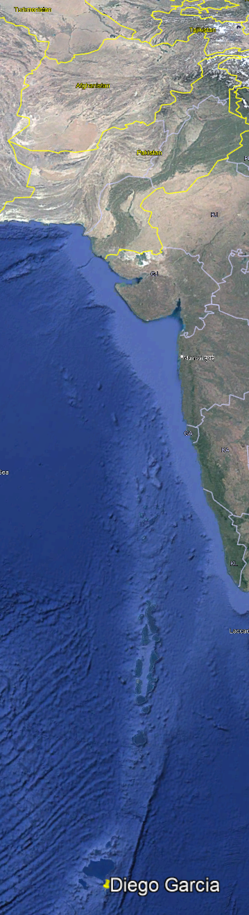
YES! YES! YES! Thanks so much for the Indian Ocean! ED we love you!