Magic Zach
-
Posts
1990 -
Joined
-
Last visited
-
Days Won
1
Content Type
Profiles
Forums
Events
Everything posted by Magic Zach
-
Thanks for posting this. I hope, like the armor plating, this gets the attention it deserves.
- 18 replies
-
- 1
-

-
- 50 caliber
- ballistics
- (and 1 more)
-
 The OpenBeta update today has resolved many issues! However there are still some remaining. The easy code fixes for the Mosquito remain untouched. And Mosquito aside, there are the model and additional new armor pieces to be added as well. This list includes: P-51D: -Addition of coolant header armor P-47D: -Addition of bulletproof windscreen -Addition of frontal armor piece Fw190A/D: -Separation of the main armor plate into the seat armor, shoulder armor, and "back" armor on each side (though the current changes made are something good to hold over for now) Spitfire: -Addition of 20mm magazine armor (can't find more definitive proof of this piece) Mosquito: -Addition of armor plate just aft of gun bay -Removal or thickness/material change of the sloped armor on the Mosquito's nose Bf-109: -Galland panzer armor frame (particularly the upper portion) around bulletproof glass protecting back of pilot head
- 29 replies
-
- 4
-
-
- protection
- dcs
- (and 17 more)
-
[4K TEXTURE OVERHAUL, WIP] Magic's Modified Mustang Makeup
Magic Zach replied to Magic Zach's topic in DCS: P-51D Mustang
Oil radiator got its work done today -
reported earlier P-51 Flap Blowup Characteristics
Magic Zach replied to Magic Zach's topic in Bugs and Problems
The pins are bolts, of two types. You bring up a good point about them though. It would appear that rather than the torque tube arms failing, it would be the hinge on said torque tube arm that would fail first. - @grafspee RE synchronous flap failure: This appears to have been ensured by the different bolt widths used between the torque tube arms connecting the strut, and the arms connecting the flaps. The bolts used to connect the flaps to the torque tube have a larger diameter than those connecting the strut to the torque tube. This would ensure that if there was an overpressure on the mechanical system, the first hinge to give would be the strut to the torque tube. This would fail both flaps, but at least both flaps would fail together, connected by the torque tube. -The inclusion of shear nuts, and the specific difference of bolt diameters between the flap hinges and the strut hinges also would be evidence that the bolts were the intended breakage point. -
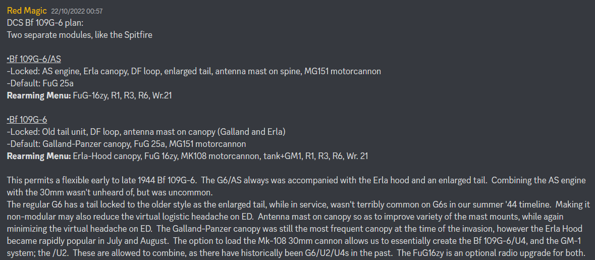
My brainstorming idea for how a 109G6 could be implemented into DCS, from a short while ago: null

-
Yeah 109, especially the later ones as the planes got faster, were notorious for having really bad control stiffness.
-
Honey, I developed FFB joystick (DIY)
Magic Zach replied to propeler's topic in PC Hardware and Related Software
Hello! Just found this thread and I'm wondering how progress is going since the OP two years ago. Looks very promising! -
UPDATE! As @NineLine recommended, I got in contact with Numbers. He's answered many questions regarding the Mosquito's armor, and even revealed there is another piece of armor on the Mosquito, not featured in DCS. I've updated the relevant post on this thread to reflect the new information. Hopefully this will make it into one of the DCS updates as well, alongside or shortly following armor fixes to the other warbirds.
-
reported earlier P-51 Flap Blowup Characteristics
Magic Zach replied to Magic Zach's topic in Bugs and Problems
1. While I'd agree that the flaps should fail in an overspeed condition, I don't agree that they should be blown smoothly back up without breakage, as they are in DCS currently. There's no allowance for hydraulic fluid to flow in this scenario, once flaps acheive their preset angle. To be clear, the flaps getting blown up during overspeed in DCS is not a failure of the flaps, they are merely being blown back up and return to their position once airspeed will drop. 1a. Agreed, hydraulics wouldn't fail (this contradicts with your first point though..?). A more mechanical component seems likely to fail, and it's likely the torque tube arm attaching the strut to the torque tube, as mentioned in my final notes in the post and yourself. 1b. If you look at the video, you'll see this isn't the behavior in DCS. Flaps are undamaged by overspeeding, and can be used repeatedly. Even in the very odd case that they do actually lock. 2. This is not modeled. -
TL;DR first: The P-51 does not have it's fuel vapor line simulated in DCS. This could have a noticeable affect on how much fuel is recaptured into the fuel tank, as it could be as much as 10 gallons an hour. In close conjunction, the fuselage tank vent line (that the vapor return line feeds into) does not appear to be modeled, quite literally. Track: P-51 Fuel Vapor Return Check.trk I'm going to split this into two different parts. One for the fuel return line, and one for the fuselage tank vent. THE FUEL RETURN LINE: 1) THE ISSUE The DCS P-51 currently does not simulate fuel being returned to the fuel tanks from the carburetor. You can check this yourself by loading the P-51 with full fuel, and run on the left tank until it is empty. Then run and drain the fuselage tank next, followed by the right wing tank. You can check if any fuel was fed into the left or the fuselage tank by checking the gauges, and setting the fuel tank selector to either the left for auxillary tanks. You'll notice that no fuel will feed, the tanks are still empty. This is what's included in my track replay, linked above. 2) THE INFORMATION The fuel vapor return passes excess fuel from the carbureator back to a fuel tank. It is widely touted that this excess fuel was routed back to the left wing tank. However, starting halfway through P-51D-15 production, this line was redirected to instead feed into the fuselage tank behind the pilot, using the same opening as the fuselage tank vent line. Photos: The following two photos were taken from the Pilot Training Manual, AAF Manual 51-127-5, dated 15 August 1945, from page 20 and 22 respectively: Now here we have a maintenance manual (AN 01-60JE-2, 13-Feb-1948 Section IV, Para 14-15) stating the same thing, with some more detail. In addition, a representative drawing showing the placement and path of the fuel lines: Now, how is this dated to the P-51D-15? If you look at the schematics for the Mustang, you'll see assemblies for building the pipes to link the carbureator to the fuselage tank. Here you'll see this fuel vapor return line, returning fuel to the fuselage cell vent. On the bottom left, it reads used on P-51D Airplanes AAF 44-15253 & Subs[equent] also on AAF 44-11953 and Subs[equent]. The P-51D serial number is a D-15 airplane, halfway through their production run. So it's clear that when referring to the Californian Mustangs, it's specifically pointing out the middle of the P-51D-15 variants, when the vapor line change was implemented. However in this source, it seems that some Dallas-built Mustangs serial numbers are excluded or missed. I think we can assume though that the change occured similarly as in Cali, on the D-15s. 3) THE FIX At a rate at 10 gallons per hour or less, fuel should be fed back into the fuselage tank. For simplicity sake, it could be a generalized 7 gallons per hour, as DCS pilots will constantly change their engine settings between economic settings and military power, or even WEP. THE FUSELAGE TANK VENT LINE: 1) THE ISSUE In DCS, this fuel vent line is not in the 3D model at all 2) THE INFORMATION This was a tube that vented the fuselage tank, and gave air a place to enter the tank to stabilize the pressure as fuel was consumed. Additionally, with the fuel vapor return tube directly connected to it at the point that the joint where the vent tube met the tank, this would be the pathway that excess fuel would be leaked overboard and outside the aircraft, in the event the fuselage tank is full. Schematic drawings: Exerpts from the E&M Manual: 3) THE FIX The vent line isn't even represented visually in the cockpit, but it's in a very hard to see location so it's not that pressing. However, it is also not even seen from the outside, specifically the outlet port, that was located at the bottom of the USAAF insignia on the right side. It is an external identifying mark of Mustangs with the fuselage tank installed. And in addition, it is also where fuel will vent outside the aircraft, in the event the fuselage tank is already full, and getting fed by the fuel return line from the carburator.
-
Hello, I've been having very bad freezing with the past DCS update. The game will freeze entirely, but not crash. This only occurs when I change views (the F-keys). This is actually making DCS really frustrating to use currently.
-
Aux Hydraulic Hand-Pump Not Building Pressure
Magic Zach replied to Sport's topic in Bugs and Problems
I was wondering about this today actually. This checks out, because in the startup tutorial mission, the guy had me keep my flaps lever forwards for whatever reason, and then try to pump the hydraulics, expecting there to be a rise in pressure. Woops, sounds like the startup tutorial mission needs to be adjusted. -
reported earlier P-51 Flap Blowup Characteristics
Magic Zach replied to Magic Zach's topic in Bugs and Problems
Yerp. Here's a color coded version of that last photo btw: -
reported earlier P-51 Flap Blowup Characteristics
Magic Zach replied to Magic Zach's topic in Bugs and Problems
The accumulator is completely unrelated to the flaps operation, unless the pump (and engine) is not operating. -
reported earlier P-51 Flap Blowup Characteristics
Magic Zach replied to Magic Zach's topic in Bugs and Problems
It may not be enough to overcome the pressure on the flap surfaces, however, the check valves will still prevent the flaps from being blown up. The strut will attempt to push the flaps down, however it cannot, and the check valves ensure the flaps circuit doesn't encounter flow reversal. So the flap surface will just stay in place until either A) airspeed decreases enough that the hydraulic force overcomes the wind force on the flap surfaces; B) component failure; C) Pilot raises flaps -
TL;DR first: The flaps for the DCS P-51D get blown back up at high speed, and do not stay fixed in place like they should. There is an unusual though inconsistent exception however, when airspeed is lower than necessary with the engine idled. THE EXPECTATIONS: First let's establish what is expected for flap behavior in the P-51. I'll start with the mechanical linkages first: The P-51 actually has a rather unique flap mechanism for the fighters of the time, and are rather automatic in nature. Aircraft that used hydraulic power to move their flaps typically required the pilot to manually move their flap control lever in the cockpit up or down to actively make the flap strut actuate the flaps up or down. The pilot would then return his flap control handle to the neutral position to stop the flap movement. This is the case for the flap control in the P-47, Mosquito, and ( believe) the P-38. If you don't have or know these aircraft, you can see how these flap handles operate here, at 11:09: Now you may be wondering why the P-51's flap controls work so automatically, without requiring the pilot to determine the time when he needs to stop the flap movement. It's all in the linkages: When you push down on the flap handle to lower the flaps, this pulls the Follow Up Control Rod forwards, and thus hinge/point #1 forwards. However, hinge #3 is somewhat fixed in its position. As the Follow Up Control Arm (not the rod) is pulled forwards at hinge #1, hinge #3 acts as the fulcrum around which the Control Arm will rotate. Note that the Follow Up Control Arm is a solid linkage that extends from point #1 to point #3, and does not bend at point #2. Connected to the center of the solid Follow Up Control Arm is the Control Valve Rod Assembly, at hingepoint #2. As the Follow Up Control Arm is pulled forwards at point #1, a part of this movement is transferred to the Control Valve Rod Assembly, which is connected directly to the Wing Flap Control Valve's lever. This directs the valve to allow fluid to pass to the strut, which will push on the Torque Tube Arm, turning the Torque Tube. But how does the flap know when to stop actuating automatically? Well, as the torque tube rotates, it will pull hinge/point #3 aft via the Follow Up Control Linkage. This brings hinge/point #2 back to its previous neutral position, and thus the Flap Valve's lever back to its neutral position. This kind of automatic functionality allows the pilot to predetermine a desired setting for the flaps, and the torque tube (and flaps) will neutralize its own controls once it's found the new equilibrium between points #1 and #3, in order to bring #2 back to its neutral position. Of interesting note, the Flap Valve's lever acts essentially exactly as the flap control handle in the P-47, Mossie, and P-38, as they are usually directly linked 1:1 to each other. In case the official drawing above is too cluttered to follow, I also made these simplified drawings to try to show how this automatic function of the flaps works. Now we can start on the hydraulics: Note that I won't cover the entire layout of the hydraulics, just the parts pertaining to flaps operation. The engine driven pump will continuously supply pressured fluid to the Unloading and Relief Valve at 1500 PSI. However, the Unloading and Relief Valve will maintain the hydraulic system's pressure at a lower 1050 PSI (specifically the manual says 1000-1100 PSI). When the system pressure reaches 1050 PSI, the unloading valve will open, creating an idling circuit just between the resevoir, pump, and Unloading and Relief Valve, isolating the hydraulic system from the pump until there is a demand on the system that consumes pressure. The wing flap selector valve does not look like this as pictured, but this is merely a visual demonstration to show roughly how the flow of fluid works. Take note of the check valves on the pressure and return feed ends on the flap valve. This is how the Wing Flap Selector valve operates the flaps circuit: And of course, I've made another drawing that simplifies this, pertaining to just the flap operations: Now, with the the hydraulic and mechanical systems in mind, what should occur if the flaps are mismanaged and oversped beyond their limits? With no relief and bracketed with check valves, the hydraulics will not yield. The weak point is the mechanical linkages. If you can imagine an immense pressure exerted on to the flaps, attempting to push them up, this will apply direct pressure on to the hinges of the torque tube arms. The weakest point taking that pressure are the bolts within the hinges, which could shear. These hinges were noted to be the weakest link in the flaps' strength. As such it was designed so that in the event of overpressure on the mechanical system, the first hinge (bolt) to shear would be that connecting the torque tube to the hydraulic strut. The two hinge bolts used to connect the torque tube to the two flaps were larger in diameter than the one hinge bolt connecting the strut to the torque tube. It was critical that any failure was to occur here, as this ensured that both flaps would simultaneously fail in sync. This helped to prevent assymetric drag and lift throughout the aircraft's flight. If the flaps are oversped and the hinge fails (bolt shears), then both flaps will weathervane with the direction of wind. So, if they were previously down when being overspeed, they will both snap back upwards at most speeds. When coming in for landing, or generally very slow however, the flaps will drop on their own, as the wind force on them decreases. THE DCS BUGS: In the DCS P-51's flap behavior, there are a couple behaviors that conflict with the mechanics and hydraulics of the real aircraft. 1) Flaps blown up when they're oversped, while strut is currently actuating flaps down. What would prevent this in reality would be the two check valves that are immediately upstream and downstream of the Wing Flap Selector Valve, to prevent flow reversal. These would be what would stop the flaps from getting blown back up when oversped, while the strut is currently attempting to actuate the flaps down. This results in the flaps not moving until airspeed decreases, or the flaps snapping lose when the strut's hinge bolt shears. 2) Flaps blown up when they're oversped, after strut is finished actuating flaps down. There are now two measures in place to prevent fluid from flow reversal. Now not only are the check valves upstream and downstream (pressure and return) of the Wing Flap Selector Valve in place, but the Wing Flap Selector Valve itself will have all its poppet valves closed. This will isolate the wing flap circuit from the main circuit, holding the fluid in place. The flaps will not move, unless the flaps are oversped and snap lose when the strut's hinge bolt shears. 3) The DCS exception... However in DCS currently, if A) your engine is idled; and B) your airspeed is >100MPH, the flaps will have a chancec of finally behave correctly, and could remain fixed in place when you dive with them. Why is it odd? Because no matter the other external factors (aside from the pilot moving the flap handle in the cockpit), so long as the flaps achieve the angle they were determined to match, they will "lock" (the flap selector valve will close). This, in testing, appears to be possible with full flaps as fast as 150MPH IAS. Airspeed (and the force against the flap surfaces) is what will affect if the hydraulic system has the pressure required to lower the flaps. What affects if the flaps will "lock" or not, is if the flaps reach their predetermined setting or not. Not only is 100MPH IAS too slow, but also it's only an indirect reason for determining if the flaps should "lock." Here's a video highlighting the issues: TURN ON SUBTITLES Timestamps of interest: 0:30 2:40 7:15 P-51 Flap Blowup test.trk CORRECTIONS: 1) The flaps should NOT get blown back up uncommanded under ANY circumstances, short of a component failure. The check valves and flap selector control valve ensure that fluid will not give or reverse flow to permit flaps to blow up against excessive force on the flap surfaces. 2) Add a component failure. As flaps would be oversped while deployed beyond limits, the most likely point of component failure will be the torque tube arm hinge between the strut and the torque tube. If the bolt in this hinge were to shear, this would cause both of the flaps to suddenly weathervane into the wind, and essentially flap freely. This would create some interesting problems when it would come to landing. Slapbladder if you have read this far, message me in Discord with the codephrase: Blue sky
-
Additionally we will see some damage model changes to the pilot protective armor in the next update or two. This will result in much easier PKs (as in, they're actually possible in some cases now). A8 included. You'll be able to pen the A8's armor with .303s, if shot from point-blank, whereas that was impossible to do now and earlier.
-
Fuel pressure when using external fuel tanks
Magic Zach replied to AJaromir's topic in Bugs and Problems
The external tanks didn't have their own pump per tank, but relied on the exhaust end of the vacuum pressure, as well as the engine driven fuel pump. The engine driven pump has a relief valve that ensured that the pressure output was always stable, even between itself and the booster pumps (in the main three tanks, not in our combat tanks). The engine driven pump could supply fuel properly from external tanks, soley on its own without aid of the vacuum pump, only to 10,000ft. However unless the vacuum pump were to fail, the pressure from the external tanks should be stable throughout all operating altitudes as well. What I can't find though, is a reference to what the observable pressure was when relying on the engine pump and vacuum system alone. This doesn't give a yes or no answer to your post, but it should provide some better context. -
ED stands for Extended Delays
- 68 replies
-
- 3
-
-
- gimme dat boost
- 1.58ata
- (and 4 more)
-
For the Spitfire's windscreen, the bonding agent between the layers is going to have essentially a nil effect on the overall ballistic protection, especially with these glue layers behind lesss than 1mm each. For just sim purposes, I think making the overall armored windshield glass 41mm and ignore the extra 3mm of glue would suit just fine. And while on sandwiched armor, if a 109G-6 was to come down the line later, the dural plate could practically just be 21-22mm of "solid" armor, as far as a flight sim is concerned. Thanks on the update though! Looks like between the new .50 belts and the updated armor values, this next update or two to OB is going to be a big hit!
- 29 replies
-
- 3
-
-

-
- protection
- dcs
- (and 17 more)
-
That armor behind the fuel tank was dural, not steel. 30 laminations, 22 gauge. The other armor was steel, though by late war the quality of it was significantly reduced. That's splitting hairs however. DCS only identifies a material as "Steel" and not "homogenous steel" and "face-hardened steel", which can give a noteable, but at our armor values only a very slight improvement to protection, around only 1mm. Considering we're making a jump from 22mm to ~8mm for some, I'm not going to get that specific, especially when I don't have more complete information on it, like pure armor thickness values.
-
[4K TEXTURE OVERHAUL, WIP] Magic's Modified Mustang Makeup
Magic Zach replied to Magic Zach's topic in DCS: P-51D Mustang
Progress may slow somewhat for a while again, just because I've been getting slammed with work. Luckily, what I think may be one of or was the most difficult area of the aircraft has just had the main bulk of the layout completed. All that remains is to mirror it to the right side, then make right-side specific adjustments. Work now has pushed to focusing on the mid-fuselage section! 1) Here you can see some of the newest added detail to the enclosure around the canopy. This new large panel covering the bulk of the mid-fuselage area has a new rivet size that wasn't seen on the engine cowlings: AD6. These new large rivets are used amongst the medium sized AD5 and slightly smaller AD4 rivets on this same panel. If you look closely you will be able to spot the different sized rivets when they're nearby each other. Hint: look around the flare gun port for one. Regarding the red objects, these go on the right side of the aircraft. However because of the orientation of the drawings, it is easier to create this on the left side, then flip them to the right later. This helps ensure proper dimensions. 2) The doors finally got completed on the cowlings! They've received some rounded corners, and the hinges they so needed. This is taken from below the bird. 3) More doors! Hinges included now. Top perspective. Here you can also see a new original panel that got added, that was missing by default. You can spot it, a skinny rectangular cover in the bottom right of this photo 4) I wanted to show this especially because it shows the irregularity of spot welds. Spot welding was for a large part just done freely by hand, with little measuring work done prior. As such, they tended to be a bit haphazardly placed on the real aircraft, and this jitter in the DCS spotwelds is how I attempt to replicate that effect. 6) Canopy frame is finally done! Including the frame around the windshield and side windows. This also came with new, originally-drawn panels added to the Mustang. -
UPDATE!! I'm now given the impression that the 109K-4 did NOT have a dural plate behind the fuel tank. If we look at the section Waffen/Panzergewicht (Weapon [Weight]/Armor Weight), we will see these weights displayed in tons of kg. You will notice that as we transition from the G-6 to the G-14 and K-4, with the addition of the MW-50 tank there came a removal of 32kg of armor weight, from 78kg to 46kg. Considering that the MW-50 tank is mounted in the same section as the duraluminum plate, and it's the only piece of armor in that section, it stands to reason that it is the only armor that was affected when the overall armor weight was decreased. We can subtly check this as well. Dural as a density(p) of 2790kg/m^3, according to Google. With an apparent mass of 32kg, and we know the width of the plate at 21-22mm (either/or, depending on the report you read, using 22mm this time), we can find the plate's face area. Mass/(width*p) will give the face area. 32/(2790*0.022) = ~0.52 square meters of face area. The square root of the result is 0.72m. So if have have a square plate of this dural, it's sides measure 0.72m by 0.72m. This, if we eyeball, looks about the same area as the aft face of the fuel tank. This seems to identify the removed armor for the K-4 as that dural plate. I will not remove the dural armor section on my Bf 109K-4 post much farther above, so people can stay up to date to additions here while having all the context. However, I will edit that post to make a note that this armor was excluded on the Kurfurst. The Bf 109K-4 does not have a duraluminum plate aft of the fuel tank.
- 29 replies
-
- 3
-
-
- protection
- dcs
- (and 17 more)
-
reported Incorrect Belt Composition for P51 and P47
Magic Zach replied to Cass's topic in Western Europe 1944-1945
So stoked to see this! -
The 47 was one of the kickstarter aircraft too iirc. The last one to be done, other than the 262. Which it seems won't happen