Search the Community
Showing results for tags 'p-51'.
Found 19 results
-
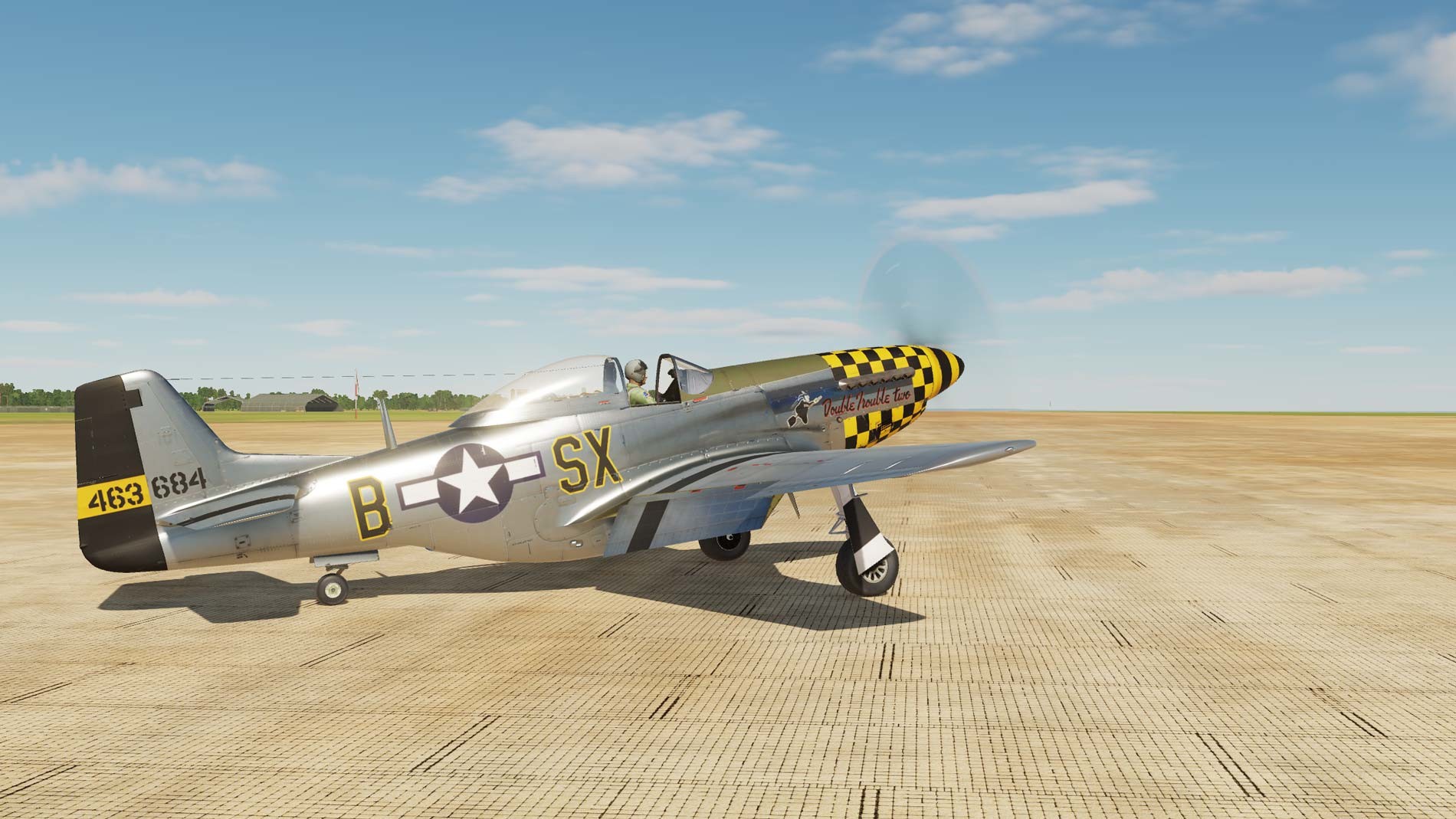
 This mod is a texture revamp of the default P-51D skins within DCS. It is an attempt to bring the Mustang's graphical fidelity closer to ED's latest texture standards. Currently it is only available in 2K, as the 4K texture overhaul is still WIP. See latest posts on this thread. Version: 1.1 (11/16/21) I have returned to this project in late October 2022, and the progress on a 4K texture Mustang has begun! For progress updates, be sure to check the latest posts on this thread. This is a WIP personal project. That means that working on this depends and uses my time, so I'm not going to be consistent. And the WIP also means that this mod will continually be updated! That means for the latest version with the newest features and latest bug fixes, you need to check in here or the DCS Userfiles occasionally. I will make a post here for every update I make. This thread is primarily for bug reports from you guys, feedback, and progress updates from myself. "Progress updates? Like what?" I will try to do major updates in phases. Planned features upcoming, in lose order, are: additional/modified weathering, increased texture resolution, completely overhauled rivet and fastener scheme, followed by an overhauled normal map. These last two are pretty far off. We'll see how this goes. As I work on these, I'll probably post little snips of the work in here. NOTE: NOT ALL SKINS FOR THE 51 ARE CURRENTLY INCLUDED. MORE MAY COME LATER. Modified default skins currently include: RAF 19 Sqn Jun 44 RAF 64 Sqn Jun 44 RAF 112 Sqn RAF 122 Sqn Jun 44 RAF 129 Sqn Jun 44 RAF 306 Sqn Jun 44 RAF 315 USAF 84th FS USAF 363rd FS USAF 364th FS USAF 375th FS USAF 485th FS USAF 302nd FS, RED TAILS (v1.1) Bare Metal (v1.1) Download for the 2K version is available here on the DCS website: Magic's Modified Mustang Makeup [M4] (digitalcombatsimulator.com)
 -
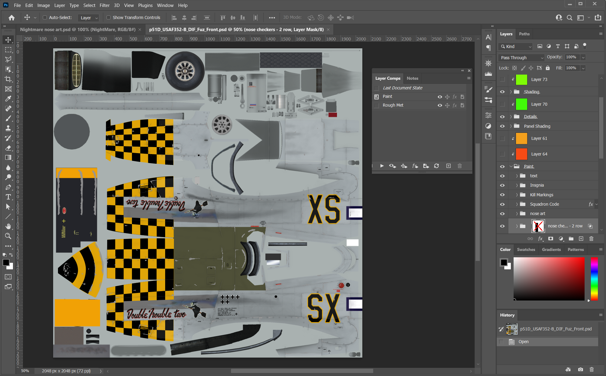
This is in reference to this skin: https://www.digitalcombatsimulator.com/en/files/3318427/ To use as-is Extract to C:\Users\[your user]\Saved Games\DCS\Liveries\P-51D You can delete source folder if desired (or keep it, it won't hurt anything) To use Photoshop source files As I am quite new to DCS -- but definitely not to Photoshop, I wanted to setup a PSD file with the following objectives: Make changes to the paint and roughmet files in the same source file Control different elements of the roughmet individually (took a lot of trial and error to learn about roughmets in general (first time working with them). Since the P-51 is so sensitive to metallic textures, this became very important. Other planes won't need as detailed source files. Setup multiple options to invasion stripes/etc for simple toggle/masking/un-masking changes Make it as easy as possible to make changes to the paint, and export paint and roughmet files from the same source Because of this, however, I admit the source files might be a bit overwhelming and confusing to use for those who are not very experienced in Photoshop, so I wanted to give a few tips/notes. Using layer comps The main premise of the source files are to use layer comps to control the visibility of different layers/groups. This let me separate out all the elements I wanted to control in the roughmets and use clipping mask color layers to edit each one individually. But, it makes for a lot more layers in the source file. If you open the layer comps window, you can show the "Paint" layer comp and see/export the paint DDS, and switch to the "RoughMet" layer comp and see/export the roughmet layer comp. Simple. Export, change layer comp, export -- done. One thing that is very important to remember is if you change the visibility of a layer/group/mask in the paint layer -- when you switch to the "RoughMet" layer comp, you will have to make the same layer/group/mask visibility changes. The layer comps remember visiblity -- but nothing else. BTW, it is a good idea to update the layer comp before you switch to the other one -- otherwise your changes won't be saved. To do this, select the layer comp, then right-click on it again and select the update option. Changing Squadron/Aircraft Codes through Smart Objects Most of the things you will want to change (except invasion stripes, for example) probably won't need much editing of the layer comps however as they use smart objects. To change a smart object, you just double-click on it and edit it as if it were a different file. Because it is a smart object, you shouldn't need to update the roughmet visibilities at all. Simply export, change to the roughmet layer comp and export that. The changes to the smart object will automatically be reflected in the roughmet layer comp. Changing Invasion stripes The invasion stripes are setup as two different groups -- one for single stripes, one for full stripes. You can show/hide these as needed to create the look you are after. For example, you can have a single upper stripe and full lower by showing the full stripes group, but hiding the upper wing stripes, and keeping the single stripe group visible. Please note, if you make changes to the visibility of these groups, you will have to make the same changes when you switch to the roughmet layer comp before exporting. All the rest The rest is relatively basic Photoshop stuff. You can change colors of paint elements that exist, use one nose stripe or two. Just play around and make your favorite squadron or your own custom fantasy squadron. I also included some PNG files of the letters and numbers I used so you can copy/paste whatever squadron/aircraft codes/serial numbers you want. Editing the RoughMet layers I am no expert in RoughMets, and there are a lot of great tutorials on YouTube, but I setup the files so you could edit the roughmet elements individually if you wanted. You will want to show the channels panel, as that is how they files are used Red channel: black = darker shadows Green channel: black = more glossy Blue channel: black = less metallic Export the DDS files Obviously, as will all other skins, you will need a DDS plugin to export the Photoshop files to the DDS. Just make sure you enable the Mipmap option when exporting. Change the aircraft name in the description.lua file The first thing you will want to do when creating your own skin is edit the description.lua file to change the name of the skin that gets selected inside DCS. Open the file in Notepad++ and scroll to the very bottom to change the name = "352nd Double Trouble two" to whatever you want. This will be what DCS shows you when selecting the skin. When you export the DDS files, you could overwrite what is there and everything will work fine. However, if you change the names of the DDS files, you will also have to change them in the description.lua file to point to you new names. The best thing to do is edit the _USAF352-B in the file name so something like "_mySkin". Then you can do a fine/replace inside Notepad++ and replace "_USAF352-B" with "_myskin" (without the quotes). Fwew, that was a lot. If you made it this far, I applaud your perseverance. I know it looks daunting, but in practice, it is quite simple to use once you get the hang of it. If anyone has questions, please let me know. if there is enough questions/interest, I might make a video about it -- but I am no YouTuber.

-
TL;DR first: The flaps for the DCS P-51D get blown back up at high speed, and do not stay fixed in place like they should. There is an unusual though inconsistent exception however, when airspeed is lower than necessary with the engine idled. THE EXPECTATIONS: First let's establish what is expected for flap behavior in the P-51. I'll start with the mechanical linkages first: The P-51 actually has a rather unique flap mechanism for the fighters of the time, and are rather automatic in nature. Aircraft that used hydraulic power to move their flaps typically required the pilot to manually move their flap control lever in the cockpit up or down to actively make the flap strut actuate the flaps up or down. The pilot would then return his flap control handle to the neutral position to stop the flap movement. This is the case for the flap control in the P-47, Mosquito, and ( believe) the P-38. If you don't have or know these aircraft, you can see how these flap handles operate here, at 11:09: Now you may be wondering why the P-51's flap controls work so automatically, without requiring the pilot to determine the time when he needs to stop the flap movement. It's all in the linkages: When you push down on the flap handle to lower the flaps, this pulls the Follow Up Control Rod forwards, and thus hinge/point #1 forwards. However, hinge #3 is somewhat fixed in its position. As the Follow Up Control Arm (not the rod) is pulled forwards at hinge #1, hinge #3 acts as the fulcrum around which the Control Arm will rotate. Note that the Follow Up Control Arm is a solid linkage that extends from point #1 to point #3, and does not bend at point #2. Connected to the center of the solid Follow Up Control Arm is the Control Valve Rod Assembly, at hingepoint #2. As the Follow Up Control Arm is pulled forwards at point #1, a part of this movement is transferred to the Control Valve Rod Assembly, which is connected directly to the Wing Flap Control Valve's lever. This directs the valve to allow fluid to pass to the strut, which will push on the Torque Tube Arm, turning the Torque Tube. But how does the flap know when to stop actuating automatically? Well, as the torque tube rotates, it will pull hinge/point #3 aft via the Follow Up Control Linkage. This brings hinge/point #2 back to its previous neutral position, and thus the Flap Valve's lever back to its neutral position. This kind of automatic functionality allows the pilot to predetermine a desired setting for the flaps, and the torque tube (and flaps) will neutralize its own controls once it's found the new equilibrium between points #1 and #3, in order to bring #2 back to its neutral position. Of interesting note, the Flap Valve's lever acts essentially exactly as the flap control handle in the P-47, Mossie, and P-38, as they are usually directly linked 1:1 to each other. In case the official drawing above is too cluttered to follow, I also made these simplified drawings to try to show how this automatic function of the flaps works. Now we can start on the hydraulics: Note that I won't cover the entire layout of the hydraulics, just the parts pertaining to flaps operation. The engine driven pump will continuously supply pressured fluid to the Unloading and Relief Valve at 1500 PSI. However, the Unloading and Relief Valve will maintain the hydraulic system's pressure at a lower 1050 PSI (specifically the manual says 1000-1100 PSI). When the system pressure reaches 1050 PSI, the unloading valve will open, creating an idling circuit just between the resevoir, pump, and Unloading and Relief Valve, isolating the hydraulic system from the pump until there is a demand on the system that consumes pressure. The wing flap selector valve does not look like this as pictured, but this is merely a visual demonstration to show roughly how the flow of fluid works. Take note of the check valves on the pressure and return feed ends on the flap valve. This is how the Wing Flap Selector valve operates the flaps circuit: And of course, I've made another drawing that simplifies this, pertaining to just the flap operations: Now, with the the hydraulic and mechanical systems in mind, what should occur if the flaps are mismanaged and oversped beyond their limits? With no relief and bracketed with check valves, the hydraulics will not yield. The weak point is the mechanical linkages. If you can imagine an immense pressure exerted on to the flaps, attempting to push them up, this will apply direct pressure on to the hinges of the torque tube arms. The weakest point taking that pressure are the bolts within the hinges, which could shear. These hinges were noted to be the weakest link in the flaps' strength. As such it was designed so that in the event of overpressure on the mechanical system, the first hinge (bolt) to shear would be that connecting the torque tube to the hydraulic strut. The two hinge bolts used to connect the torque tube to the two flaps were larger in diameter than the one hinge bolt connecting the strut to the torque tube. It was critical that any failure was to occur here, as this ensured that both flaps would simultaneously fail in sync. This helped to prevent assymetric drag and lift throughout the aircraft's flight. If the flaps are oversped and the hinge fails (bolt shears), then both flaps will weathervane with the direction of wind. So, if they were previously down when being overspeed, they will both snap back upwards at most speeds. When coming in for landing, or generally very slow however, the flaps will drop on their own, as the wind force on them decreases. THE DCS BUGS: In the DCS P-51's flap behavior, there are a couple behaviors that conflict with the mechanics and hydraulics of the real aircraft. 1) Flaps blown up when they're oversped, while strut is currently actuating flaps down. What would prevent this in reality would be the two check valves that are immediately upstream and downstream of the Wing Flap Selector Valve, to prevent flow reversal. These would be what would stop the flaps from getting blown back up when oversped, while the strut is currently attempting to actuate the flaps down. This results in the flaps not moving until airspeed decreases, or the flaps snapping lose when the strut's hinge bolt shears. 2) Flaps blown up when they're oversped, after strut is finished actuating flaps down. There are now two measures in place to prevent fluid from flow reversal. Now not only are the check valves upstream and downstream (pressure and return) of the Wing Flap Selector Valve in place, but the Wing Flap Selector Valve itself will have all its poppet valves closed. This will isolate the wing flap circuit from the main circuit, holding the fluid in place. The flaps will not move, unless the flaps are oversped and snap lose when the strut's hinge bolt shears. 3) The DCS exception... However in DCS currently, if A) your engine is idled; and B) your airspeed is >100MPH, the flaps will have a chancec of finally behave correctly, and could remain fixed in place when you dive with them. Why is it odd? Because no matter the other external factors (aside from the pilot moving the flap handle in the cockpit), so long as the flaps achieve the angle they were determined to match, they will "lock" (the flap selector valve will close). This, in testing, appears to be possible with full flaps as fast as 150MPH IAS. Airspeed (and the force against the flap surfaces) is what will affect if the hydraulic system has the pressure required to lower the flaps. What affects if the flaps will "lock" or not, is if the flaps reach their predetermined setting or not. Not only is 100MPH IAS too slow, but also it's only an indirect reason for determining if the flaps should "lock." Here's a video highlighting the issues: TURN ON SUBTITLES Timestamps of interest: 0:30 2:40 7:15 P-51 Flap Blowup test.trk CORRECTIONS: 1) The flaps should NOT get blown back up uncommanded under ANY circumstances, short of a component failure. The check valves and flap selector control valve ensure that fluid will not give or reverse flow to permit flaps to blow up against excessive force on the flap surfaces. 2) Add a component failure. As flaps would be oversped while deployed beyond limits, the most likely point of component failure will be the torque tube arm hinge between the strut and the torque tube. If the bolt in this hinge were to shear, this would cause both of the flaps to suddenly weathervane into the wind, and essentially flap freely. This would create some interesting problems when it would come to landing. Slapbladder if you have read this far, message me in Discord with the codephrase: Blue sky
-
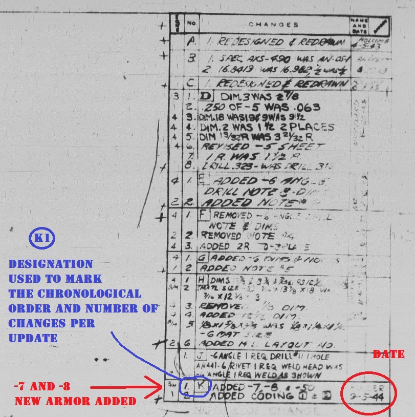
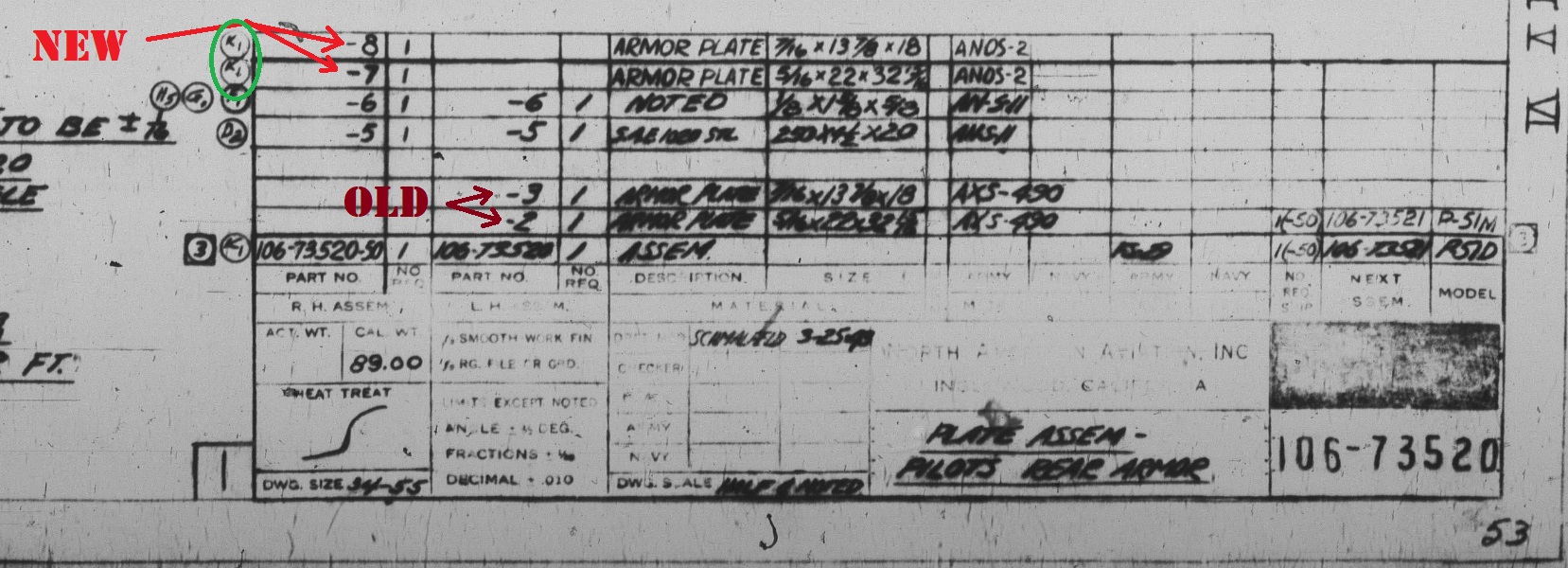
TL;DR first: The P-51 does not have it's fuel vapor line simulated in DCS. This could have a noticeable affect on how much fuel is recaptured into the fuel tank, as it could be as much as 10 gallons an hour. In close conjunction, the fuselage tank vent line (that the vapor return line feeds into) does not appear to be modeled, quite literally. Track: P-51 Fuel Vapor Return Check.trk I'm going to split this into two different parts. One for the fuel return line, and one for the fuselage tank vent. THE FUEL RETURN LINE: 1) THE ISSUE The DCS P-51 currently does not simulate fuel being returned to the fuel tanks from the carburetor. You can check this yourself by loading the P-51 with full fuel, and run on the left tank until it is empty. Then run and drain the fuselage tank next, followed by the right wing tank. You can check if any fuel was fed into the left or the fuselage tank by checking the gauges, and setting the fuel tank selector to either the left for auxillary tanks. You'll notice that no fuel will feed, the tanks are still empty. This is what's included in my track replay, linked above. 2) THE INFORMATION The fuel vapor return passes excess fuel from the carbureator back to a fuel tank. It is widely touted that this excess fuel was routed back to the left wing tank. However, starting halfway through P-51D-15 production, this line was redirected to instead feed into the fuselage tank behind the pilot, using the same opening as the fuselage tank vent line. Photos: The following two photos were taken from the Pilot Training Manual, AAF Manual 51-127-5, dated 15 August 1945, from page 20 and 22 respectively: Now here we have a maintenance manual (AN 01-60JE-2, 13-Feb-1948 Section IV, Para 14-15) stating the same thing, with some more detail. In addition, a representative drawing showing the placement and path of the fuel lines: Now, how is this dated to the P-51D-15? If you look at the schematics for the Mustang, you'll see assemblies for building the pipes to link the carbureator to the fuselage tank. Here you'll see this fuel vapor return line, returning fuel to the fuselage cell vent. On the bottom left, it reads used on P-51D Airplanes AAF 44-15253 & Subs[equent] also on AAF 44-11953 and Subs[equent]. The P-51D serial number is a D-15 airplane, halfway through their production run. So it's clear that when referring to the Californian Mustangs, it's specifically pointing out the middle of the P-51D-15 variants, when the vapor line change was implemented. However in this source, it seems that some Dallas-built Mustangs serial numbers are excluded or missed. I think we can assume though that the change occured similarly as in Cali, on the D-15s. 3) THE FIX At a rate at 10 gallons per hour or less, fuel should be fed back into the fuselage tank. For simplicity sake, it could be a generalized 7 gallons per hour, as DCS pilots will constantly change their engine settings between economic settings and military power, or even WEP. THE FUSELAGE TANK VENT LINE: 1) THE ISSUE In DCS, this fuel vent line is not in the 3D model at all 2) THE INFORMATION This was a tube that vented the fuselage tank, and gave air a place to enter the tank to stabilize the pressure as fuel was consumed. Additionally, with the fuel vapor return tube directly connected to it at the point that the joint where the vent tube met the tank, this would be the pathway that excess fuel would be leaked overboard and outside the aircraft, in the event the fuselage tank is full. Schematic drawings: Exerpts from the E&M Manual: 3) THE FIX The vent line isn't even represented visually in the cockpit, but it's in a very hard to see location so it's not that pressing. However, it is also not even seen from the outside, specifically the outlet port, that was located at the bottom of the USAAF insignia on the right side. It is an external identifying mark of Mustangs with the fuselage tank installed. And in addition, it is also where fuel will vent outside the aircraft, in the event the fuselage tank is already full, and getting fed by the fuel return line from the carburator.
-
As in the title. Players might as well never close the canopy if it costs no speed to them, and only gives more visibility. Same with the P-51. P-47 and Spitfire do have some additional drag, but it's extremely little, only costing a handful of knots of top speed at SL. The drag from an open canopy should probably be a lot higher for those. canopy drag test.trk
-
My experience is with the P-51D but probably applies to all the tailwheels. I would like to see DCS improve the flight model particularly for when the plane is on the runway both taking off and landing. The plane does wild yaws that are very unrealistic. I understand about torque and ground loops and such but planes don't travel down the runway sideways in real life. The amount that the plane can yaw before it stalls or has a wing strike needs to be more limited.
- 51 replies
-
- 1
-

-
- ground loop
- yaw
- (and 2 more)
-
 Simplest possible mission (~1 second length). Single P-51 start-from-runway ("client") on Cacausus map. All mission defaults taken. Clean 2.7 install. -Start mission (directly or via Mission Editor, same result) -Spawn -ESC -> Quit -Fly again -> CTD crash to desktop Very repeatable, happened ~10 times, never not happened. Replacing P-51 with Spitfire or Bf 109, no CTD. Include mission file and crash log generated by DCS. Open Beta "2.7.0.5118". PC spec, see signature (Commodore 64) dcs.log-20210505-082129.zip P-51 CTD crash.miz
 -
So I noticed multiple times when spawning P-51 start on runway engine spins up. When I touch the HOTAS throttle lever (Warthog) it goes to idle. Same thing Spitfire. HOTAS throttle idle but engine roars away until lever touched on mission start. Began with first 2.7 release I think. Yes, I checked the checkmark, I've relied on it for years.
-
99% sure it didn't used to work like that. Rotary is available with keyboard binding ("[1]") (was it always?). Fix: remove rotary when mouse clicking. Ie remove jumps from first-last and last-first while mouse clicking. Is mouse click rotary a new feature? Make more sense if it didn't (again 99% sure it didn't used to).
-
P-51 have (had) the best trim. Hold a few seconds and speed much faster. Not working for for pitch trim with 2.7.
-
Been wondering about this behavior. Like, should you keep advancing throttle to keep power up until supercharger kicks in while climbing? Ok, the MP jump on supercharger kick in, that's how it worked. http://www.aviation-history.com/engines/merlin.htm
-
I don't have a lot of experience in the P-51 only 200 hrs. I figured out some things after a lot of trials and burns. One is for those who want to learn how to perform close turns with the Mustang, Close turns The other one is for those who want to learn how to climb to high altitutes without losing their engines. Climb Hope these will help somebody. Thank you for your time.
-
EDIT/ADD: -Boost gauge tricky to read. Further down thread (see image) I found "true non bugged" idle boost ca -6.2. -I stupidly wrote zero (0) when meaning lowest idle boost. Edited to -6.2 in text (red). At no point during testing (all tests, all posts) did it actually show zero (0). Except engine off obviously. -Spitfire. Bugged (idle) high boost shifts between -3 or -4 depending HOTAS RPM level max/min. Might jump straight to post #6 (first with image). Previous posts I grasped less what's happening. Also, probably not intermittent (one thing I didn't grasp). I crashed Spitfire, did Quit -> Fly again. Suddenly Spitfire rolled on Spawn Rwy. Spitfire & P-51 both increase idle <1000 ~1500, Boost goes to -4 Spitfire instead of idle 0 -6.2. Seen once P-51, Spitfire all the time. Not tried others. When observed with Thrustmasters own software "Device Analyzer". All buttons work, analog hit correct endpoints (0-16383 for example). When plugging in the throttle the boost & rpm increases. What can this be? Throttle otherwise seems to work as it should, ie I can increase & decrease, just starting from boost -4 instead of zero -6.2 (Spitfire). Calibration? This has never happened before, bought 2018, so ie five years old, so I fear something more problematic is afoot.
-
Here are a very few of the photos I took at the Battle of Britain Air Show at Duxford over a weekend in 2018. It rained on the Saturday but Sunday the sun turned up. I hope you like them?
-
1) These Controls are interchanged. How they list in Controls tab: RShift + B controls "Emergency By-Pass" and RCtrl + B controls "Deluter" They're inverted. ~ 2) Oxygen is not replenished by refuel/rearming. The only way to replenish oxygen is by doing a repair. 3) There is no way to shut off oxygen completely (to save it).
-
A little amusing bug. On repair Spitfire gets moved to tail wheel outside deck position. Proposed cause: (Nose wheeled) carrier jets gets pushed back to main wheels near deck edge. Very short track: -Air start -Belly land -Repair Track 100% default installation, no mods (main folder repaired, forced new Saved_Games folder). ed/add. Though I can (once at least) start engine, pull fully onto deck and even take off, plane is damaged. It takes damage after every repair when rear fuselage hits deck.
-
Haven't tried them but interesting. P-51 have 3 different ammo loadouts, Bf109 have 5 loadouts.
-
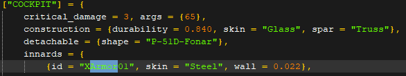
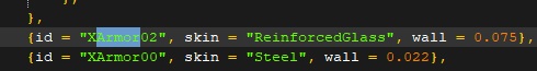
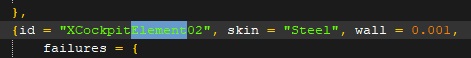
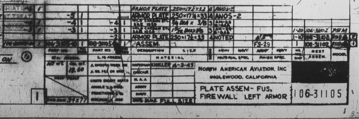
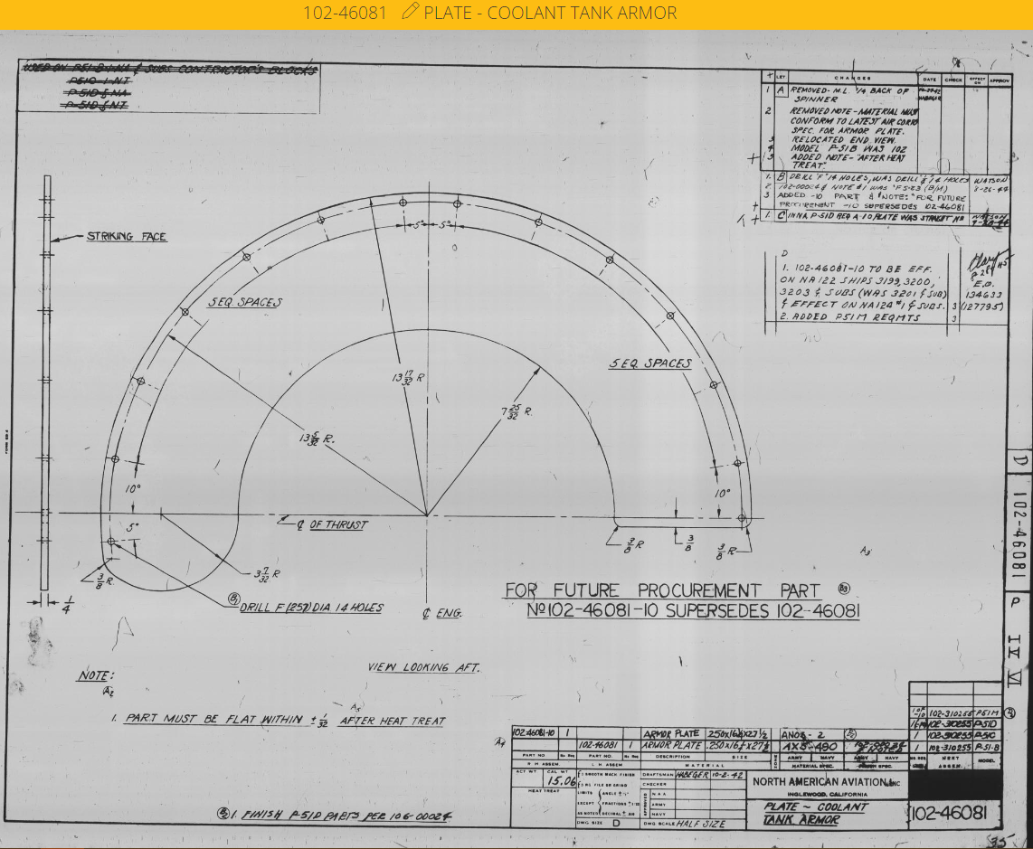
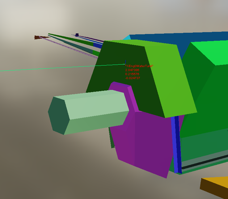
12/16/22 Preface: In this Friday's OpenBeta update, the easy coding fixes have been added for the P-51, 190s, Spitfire, 109, and 47. However, the Mosquito has been missed. Additionally, the armor plates that are missing from DCS entirely haven't yet been included. Items that were fixed in the 12/16 OpenBeta update will be highlighted in green, and marked with the update date. TL;DR: Many warbirds have incorrect armor values, or are missing armor. If you open the x-ray.edm in the Modelviewer, and the individual aircraft's Lua, you can see the IDs from the Modelviewer and see what those objects' properties are. Please click on the photos here, as while I've minimized them in this post so it doesn't get cluttered, but if you click on them you will see them in better resolution. The P-51D (INCORRECT): [FIXED: DEC 16, 2022]The headrest and seat back armor (aka XArmor01 and XArmor00) - If we open Aircorps Library and look at the drawings for the late P-51D, like ours, we will see that these are two pieces of armor welded together. The headrest being 7/16", or 11mm...and the seat back being 5/16", or 8mm thick. Meanwhile in DCS, it is given a thickness of 22mm! For both plates! Almost three times the value of most of the area of the armor. I have an idea on how this value came to be, but I'll drop it into the spoiler below: [FIXED: DEC 16, 2022]The armored glass (aka XArmor02) - In DCS, it is given a thickness of 75mm. Using the schematics from Aircorps Library, we can again see that it is 1.5" thick, or 38mm. [FIXED: DEC 16, 2022]The instrument panel (aka XCockpitElement02) - In DCS, this is given a thickness of just 1mm! In truth, the instrument panel is a part that's for once, thicker in truth, coming out to 0.128", or 3.25mm. [FIXED: DEC 16, 2022]The firewall (aka XArmor03) - This is given a value of 12mm in DCS, or just a scratch under 1/2". For our 51D, it appears that a more possible value would've been 1/4", or 6.35mm. The P-51D (MISSING): The coolant header tank armor - This is a piece of armor that has been missing from the Mustang's damage model. It is 1/4" thick, or 6.35mm, and lies just forward of the coolant header tank within the engine nacelle, between the coolant header tank and the spinner. In summary for the P-51: -[FIXED: DEC 16, 2022]Change XArmor00 from 0.022 to 0.008 -[FIXED: DEC 16, 2022]Change XArmor01 from 0.022 to 0.011 -[FIXED: DEC 16, 2022]Change XArmor02 from 0.075 to 0.038 -[FIXED: DEC 16, 2022]Change XArmor03 from 0.012 to 0.00635 -[FIXED: DEC 16, 2022]Change XCockpitElement02 from 0.001 to 0.00325 -Add coolant header tank armor. Steel, 0.00635
- 29 replies
-
- 10
-
-
- protection
- dcs
- (and 17 more)
-
Как установить мод и активировать мод на звук на P-51D и TF-51D?