Leaderboard

Popular Content
Showing content with the highest reputation on 12/19/22 in all areas
-
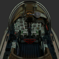
Octopus-G and his La-7: more:11 points
-
Hey @Furizand everyone replying. We're marked this as a potential bug as we are seeing an inconsistency in the boresight alignment. Thank you for bringing this to our attention.6 points
-
Again BIG Thank you guys!6 points
-
I think you are about 10+ years too late to complain about the Black Shark validity. I would welcome more what-ifs and testbeds into DCS, as with the Black Shark it makes for a very enjoyable flight sim experience as well as gives us some aircraft where we might not be able to do them otherwise.6 points
-
It's nothing to blame ED. There was an API change, I adopted SSA to this change, and we are all happy ;-).5 points
-
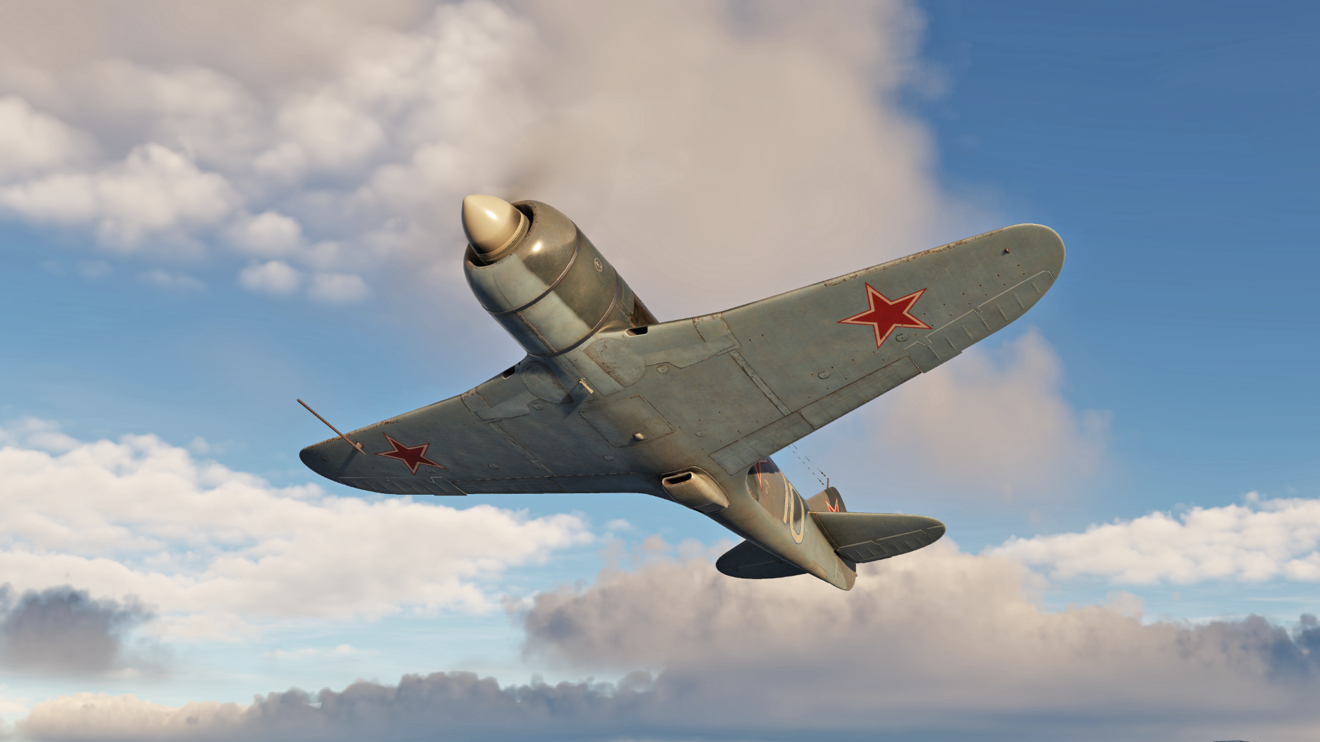
In order to entertain you while you are expecting the new DCS: La-7 module, we have prepared for you a series of short notes about the module development, about the aircraft and its elements, about personalities associated with the aircraft. Let's start with a little comparison. Against the I-16, a representative of the fighter aviation of the beginning of World War II, the La-7 aircraft is significantly more advanced not only as a combat vehicle, but also as an aircraft to pilot. The first thing to note is the chassis of course. Those painful multi-stage manual procedures to raise and lower the landing gear are left behind. From now on, the landing gear is just controlled by setting the hydraulic handle to the appropriate position, which allows the pilot to focus on the task. In addition, the aircraft has pitch and yaw trimmers that reduces pilot fatigue during flying, increasing the feeling of comfort. The motor start-up procedure no longer requires external electrical power or manual spinning of the starter. The autonomy of the procedure is ensured by the onboard compressed air system. The closed cockpit is also an important element in terms of flight comfort. The only thing that differed the aircraft for the pilot in a negative direction was the presence of suffocating heat in this cockpit from a powerful engine, which the conditioning system could not cope. Fortunately, this aspect will not physically affect our virtual pilots. Of course, these minimal conveniences were the undisputed norm of that time, but truly comfortable times are coming for connoisseurs of red piston aviation!
 4 points
 -
Instead of holding the trim button to make changes on your heading, and relase it to keep the new one, just press on the rudder pedals to change that heading makes turning Heading hold off while you keep pushing the pedals, until you release them.4 points
-
4 points
-
Sorry guys, we will upload the paintkit shortly. Thank you for your kind patience.4 points
-
A promotional brochure with a mock-up image is not a disagreement, it's a sales pitch. Nor does it change the facts.4 points
-
sometimes I wonder if the HB employees lurking on this forum sit and laugh their asses of about all of our speculation and theories3 points
-
I re-installed Stable 2.7.18 as I did not have the 4080 then and wanted to update my baseline results. Here are my results with HIGH preset setting using my test track file (F-18, Caucasus): 2.7.18 2.8.1 Delta GPU FT 13.4 14.5 +1.1ms CPU FT 10.2 12.7 +2.5ms Seems that the CPU is taking a massive hit. This could explain why some are seeing huge FPS drop if they were already at the edge of their refresh rate with 2.7.18. Results with previous version 2.8.0.33006 are the same as latest 2.8.1. I use the following mods: VR Shader Mod, ReshadeVR_sharpen_color 4.9.1, F-14_VUX_v2.2, Taz1004_Better_Trees_v5_Med_Low, VR Loading Screen fix and PimaxXR/OpenComposite0.6.3/OpenXRTK. No plan to go back to OB until the problem is fixed. Unfortunately, only one version is possible with steam.3 points
-
we would need real radar simulations in order for the F-4G to be viable. For example, part of the back seat electronics include what is essentially an oscilloscope to view the waveform of any radar being seen by the EW suite, and you can dynamically select any of them on the fly. If you want to get an idea of how poorly suited the F-4G would be to the current version of DCS:World, take a look at this:3 points
-
The Hellenic Air Force had modified F-1CG (Mod 1TY) in order to carry 4 heaters (Magic or Sidewinders). Rapid gun had to do only with radar lock in dogfight and was avtivating GUN mode in HUD (it was not activating automatically any missile). In order to be able to fire any of the four misssiles you had to have the Armament Master ON, IR Missile Selection Button pressed, GUN fuze. The best locked missile was fired by pressing the misslile button. If I remember well there was a delay of 0,75 second.3 points
-
I am pretty sure that they do get some commission from third parties. Also I don't really count the BS3 as an actual release and more of a paid update. Furthermore I am not expecting the phantom to cut into the BS3 sales numbers too much as they are so different. Still I am with you in that it most likely won't be released this year but just because it isn't ready yet.3 points
-
Correct. This wasn't done following new data, instead it was needed to overhaul the limitations of a much older code.3 points
-
No one asks you to. Not a single customer owes us a single bug report. But it should be known at the same time, that simply saying "it doesn't work", does not allow us to follow up much. In this case it is a bit different, the (factual) issues are known to us (as are the more non-factual complaints and opinions), but the fact remains. That said, this thread is full of hyperbole, which does not help make a case, if I may add ever so kindly. This is where factual bug reports that leave out emotions, help your cause simply better, because they add data that helps speed up the process of fixing. The more data we have, the easier we (and ED) can pinpoint the issue and adjust what needs adjusting. Reading hyperbole or absolute statements such as "is utterly useless" does not allow for much more than acknowledging your opinion, which by all means you are entitled to have and which is by all means appreciated a priori. Of course it also invites diverse or controverse opinion as well, which everyone else is allowed to have as much as yourself, including us, btw. Hence, if you put it like that, I disagree. The phoenix is anything but useless. How would I know? Because I use it myself. And if you look closely, the experience with the phoenix is as diverse as are the users on this forum, and the difference between those who make it work and those who do not, is that the former do not open threads about it being so brilliant for them. They make a post or two, about how more or less successful they were with it (online or against XY), or post a tacview here and there, but then don't linger much, because they do not face a constantly re-occurring problem for themselves, like not getting the missile to work. This is not a remark on skill btw, just on the matter of the fact that some make it work more, and some struggle with it more. And the latter do have our full understanding. It is an older missile to employ while still "amraam enough" to trick folks into thinking it should offer the same reliability and ease of use (by truly forgetting about it once fired), both from the side of the employing platform (AWG-9) as well as on its own. But this is not true. The AWG-9's TWS was the first ever, and came with its own set of issues. For example target weighting. We use the algorithm used by the AWG-9. And it has its limits. It comes to no surprise that PDSTT was a preferred employment method IRL, but in DCS players of course do not want to drop the comfort or advantage or if you will, "leveling ability" of TWS when flying against opponents like F-15s, F-16s and F-18s which come equipped with a much more modern and reliable TWS, more modern amraams, etc. Understandable to then think: But what good is the phoenix and TWS to me, if I have to fire it like a sparrow against a slammer weilding Viper??? And this is where making the phoenix work is more complicated than making an aim120 work, it involves more pre-launch decision making and more post-launch caretaking. (But if one person can make it work against Vipers (forgot who recently posted about that), so can we all, at least theoretically. And reports like that do not stand alone, just that they are more quiet, as mentioned.) This is one side that feeds into folks having issues, and many explanations in this thread and the main thread point exactly to that. The other side are of course its remaining issues as well: they add to that complexity and make it even harder and sometimes you can do everything right and it still won't work. That is true for all missiles in DCS to some degree btw. Missiles in a sim will never be perfect, heck, they are not even perfect IRL. Just recently a new post came up about the phoenix turning 180 with an overpitched shot. Guess what, if you overpitch or "manually loft" a missile that much IRL, it could potentially encounter something eerily similar. That said, in DCS this is still a bug, because it was not coded with intention to go 180 when you crassly overloft. But you know the saying, when life sometimes simulates fiction... And it does not change the fact, that even without a single bug being present anymore, you still should not overloft it. Which just goes to show: dealing with missile issues in principle is a thing of flying fighter jets. That certain bugs are more frustrating than others is also understandable: the automatic pitch up after being notched is a thorn in our eyes just as it is in yours. The general lofting logic otoh is far less off than most make it out to be. It is supposed to go high steep fast. And we tested it: a more shallow loft results in less terminal velocity. Which goes to show: not everything being "felt" or tossed around, is always substantiated. Hence: factual bug reports help more than opinions and feelings, as much as we appreciate any kind of feedback. Just that some is actionable and some isn't really, as much as we'd want it to be. Lastly, about issues not in our hands: I am not sure who you talked to at Heatblur (it wasn't me, I've seen you sent me a PM but I hadn't had the time to reply to it yet, and hopefully my reply will answer most of it here), and who you talked to at ED. But both ED and us have a firm and commonly shared understanding that we want to improve what we can, each from their side, which @NineLine pointed out aptly above. We work together and neither of us is interested in shifting blame. But we share different responsibilities, and some things fall upon us to work on, and some fall onto ED to work on, simple as that. AI, guidance, etc - that is in ED's hands. Which does not mean that we simply go "here, fix it please." We make our case concerning these issues, trying to produce actionable data that shows where one fix would help another, where things work not as they should, or need fixing etc. Likewise ED engages with us in this dialogue and common effort the same way. We help each other, out of a common interest to improve what must and can be improved. And some things are quick and easier to fix, and ED has always been very forthcoming in helping us with numerous issues that let us improve guidance, loft, fixing various bugs with the missile, from patch to patch, ever since we adjusted the overperformance of the phoenix. But other things cannot be changed over night, like having a new AI, or some parts of guidance logic, which result in some weird outcomes like the pitch up after the notch. We first need to understand what it is wrong or causing it, to be able to fix it. When we say we are working on it, we also mean that. And as soon as we understand the cause of an issue, either on our or ED's side, it will get fixed, as always. But we keep turning in circles here on our forums about issues that are known and, in the end, are still not in our hands and affect not only the phoenix in DCS, which also means: ED is not only responsible to help us, but to help numerous 3rd parties, keep a base game progressing, keeping modules maintained, etc. The phoenix is one issue out of many. Let me conclude with: we do hear you. We heard you the first time in the guided phoenix discussions and every subsequent time, too. We agree with some, but not with everything, and in both cases thank you for your feedback. You really don't need to open extra threads about these issues (especially since that is what the guided discussion thread is for), because we are fully aware of all the remaining issues and we have been committed to them from the moment we encountered them. But at the same time a lot of the complaining stems from wrongly set expectations as well, and as someone who flies the Tomcat daily, I know that it is far from unplayable, or to circle back to the phoenix: far from useless. The issues that remain anger me as much as they do you. But they pester me far less, because within the entire complexity of employing the phoenix with maximum aid by pilot and RIO to make a successful kill shot, or defensive shot, these issues are not the primary concern. And once you develop a certain discipline for the phoenix, you may find, like me, and many other, less loud voices, that these issues factor into the balance between success and failure far less, than one would think if taking the hyperbole, the boiling emotions and the frustration shared among some too literally - if you'll pardon me for saying it a bit more directly. Either way, I can assure you: we are as interested in fixing the remaining issues as you are. Even so I would caution everyone to not think that these fixes will turn the phoenix into the magical trick for all treats that some apparently would like it to be. But most importantly: hyperbole and exaggerations will not get us there. And I cannot stress this enough: the phoenix did not get nerfed. We don't nerf stuff. It is a notion as misguided as the accusations we received before that we intentionally overpowered the missile "to sell more modules." We adjusted its overperformance to be much more realistic following newly gained insights. That is something everyone should finally get to terms with. We do not care how good or bad a missile is, or what it means for PvP etc. And while we hope that you are successful with it and have fun with it, above all we care about it being accurate. PS: I am closing the thread, because we already have a guided discussion thread for the phoenix. Please keep discussing there. Opening more threads about your gripes with the phoenix will not help speed up the process at all. Factual reports will. Thank you! https://forum.dcs.world/topic/308085-dcs-f-14-development-update-aim-54-phoenix-improvements-overhaul-guided-discussion/3 points
-
I'm currently working on a fix for the issues introduced with the latest DCS open beta version... I currently don't own the BS3 and the MB module thus currently no support...3 points
-
I’ve been reviewing a lot of the historical data on the various 50 caliber bullets used in World War 2. The DCS values for muzzle velocity and weight are different from data in the historical and contemporary sources in some instances. In the first part of this post I will present data showing the muzzle velocities, weight and dispersion for these bullets. All the data presented will be for the 36 inch Barrel Aircraft Machine Gun version of the Browning 50 caliber. In the second part, we’ll get a little more in depth with data. We will also construct firing tables and compute the trajectories of the bullets using historical methods and data. With that out of the way. Let's begin by comparing the DCS data in the CoreMods\WWII Units\Weapons\Weapons.lua file to some contemporary and historical data. The table Below shows the values In game Vs the historical data. I’ve also added some data for the M1 incendiary bullet, which was one of the most commonly used in American aircraft. DCS M2 AP DCS M8 API DCS M20 APIT M2 AP Historical Data M8 API Historical Data M20 API Historical Data M1 Incendiary V0 (Muzzle Velocity MPS) V0 (Muzzle Velocity MPS) V0 (Muzzle Velocity MPS) V0 (Muzzle Velocity MPS) V0 (Muzzle Velocity MPS) V0 (Muzzle Velocity MPS) V0 (Muzzle Velocity MPS) 830 860 875 864 899 899 912 Bullet Weight Kg Bullet Weight Kg Bullet Weight Kg Bullet Weight Kg Bullet Weight Kg Bullet Weight Kg Bullet Weight Kg 0.0458 .0403 0.0410 0.046 .042 .0396 0.040049 Da0 (Dispersion) Da0 (Dispersion) Da0 (Dispersion) Da0 (Dispersion) Da0 (Dispersion) Da0 (Dispersion) Da0 (Dispersion) 0.00085 0.00085 0.00085 0.001 0.001 0.001 0.001 100% Dispersion: Mils 100% Dispersion: Mils 100% Dispersion: Mils 100% Dispersion Mils 100% Dispersion: Mils 100% Dispersion: Mils 100% Dispersion: Mils 6.8 6.8 6.8 8 8 8 8 Below is a table of muzzle velocities for the .50 Caliber M2 AP, M8 API and M1 Incendiary in the various historical and contemporary documents.The table also includes a link to the source material. Bullet: Muzzle Velocity: FPS Muzzle Velocity MPS: Source: Link To Source M2 AP 2835 864.07 Terminal Ballistic Data 1945 https://cgsc.contentdm.oclc.org/digital/collection/p4013coll8/id/2373/rec/8 M2 AP 2845 867.11 Terminal Ballistic Data 1944 /43 https://cgsc.contentdm.oclc.org/digital/collection/p4013coll8/id/2327/rec/1 M2 AP 2845 867.11 Test Method Standard V50 Ballistic Test For Armor MIL STD-662F 1997 https://www.abbottaerospace.com/downloads/mil-std-662f-v50-ballistic-test-for-armor/ M2 AP 2845 867.11 NDRC Study Effects Of Weapon Impacts https://www.loc.gov/resource/gdcmassbookdig.effectsofimpacte01unit/?sp=421 M2 AP 2840 865.59 TM 9-225 Browning Machine Gun .50 Caliber AN-M2 Aircraft https://www.google.com/books/edition/Browning_Machine_Gun_Caliber_50_AN_M2_Ai/nXySRue3QAYC?hl=en&gbpv=1 M2 AP 2845 867.11 TM-9-2200 Small Arms https://archive.org/details/TM9-2200/page/n203/mode/2up M2 AP 2840 865.59 TM 9-219 AN M3 Basic Aircraft Machine Gun https://archive.smallarmsreview.com/archive/detail.arc.entry.cfm?arcid=7268 M8 API & M20 APIT 2946 897.89 AFM 51-44 Fighter and Fighter Bombers Employment in Tactical Air Operations https://archive.org/details/fighter-fighter-bomber-employment-in-tactical-air-operations-usaf/page/55/mode/1up M8 API & M20 APIT 2950 899.12 TM 9-225 Browning Machine Gun .50 Caliber AN-M2 Aircraft https://www.google.com/books/edition/Browning_Machine_Gun_Caliber_50_AN_M2_Ai/nXySRue3QAYC?hl=en&gbpv=1 M8 API & M20 APIT 2950 899.12 TM 9-219 AN M3 Basic Aircraft Machine Gun https://archive.smallarmsreview.com/archive/detail.arc.entry.cfm?arcid=7268 M8 API (45 Inch Barrel) 3045 982.07 FT 0.50AA-T1 1946 Firing Table M8API Heavy Barrel https://archive.smallarmsreview.com/archive/detail.arc.entry.cfm?arcid=3561 M1 Incendiary 3100 944.83 TM-9-2200 Small Arms https://archive.org/details/TM9-2200/page/n203/mode/2up M1 Incendiary 2990 911.31 TM 9-225 Browning Machine Gun .50 Caliber AN-M2 Aircraft https://www.google.com/books/edition/Browning_Machine_Gun_Caliber_50_AN_M2_Ai/nXySRue3QAYC?hl=en&gbpv=1 M1 Incendiary 2990 911.31 TM 9-219 AN M3 Basic Aircraft Machine Gun https://archive.smallarmsreview.com/archive/detail.arc.entry.cfm?arcid=7268 Below are images from the sources On Muzzle Velocity. Images Projectile Weight: For the weight data we’ll use one source, the blueprints for the projectiles. The blueprints for the projectiles have two different weights. The Standard weight and the Alternate weight. We’ll be using the Alternate weight of the projectiles, where applicable, the M2 AP, M8 API and M20 APIT. The reason for this is explained below the table. M2 AP 50 M8 API M20 API M1 Incendiary Weight 708 649 620 633 Alternate Core 708 649 612 643.5 std Core 718 662 624 633 Alt Core Kg 0.04588 0.0420 0.0396 DCS KG 0.0458 0.0403 0.041 DCS Grains 706.694 621.829 632.63 M2 AP https://archive.smallarmsreview.com/archive/detail.arc.entry.cfm?arcid=13268 M8 API https://archive.smallarmsreview.com/archive/detail.arc.entry.cfm?arcid=13265 M20 APIT M1 Incendiary According to a Ballistic Research Laboratory Report and Ordnance Research and Development .In 1943, due to supply shortages. The material for all the armor piercing cores was changed in the 50 caliber bullet. This reduced the weight of all the 50 caliber projectiles which made use of an armor piercing core, the M2 AP M8 API, and M20 APIT. The majority of these bullets were assembled with the alternate core. Which is why the weights presented are based on the alternate weight of the projectile. Army Ordnance Research and Development Report Dispersion: Preface, Units of Measure. In the discussion below the data is given in the value of mils. In this case we are referring to milliradians. Where one mil is = 0.057296 degrees. At a range of 100 feet, 1 mil = 1.2 inches. A table from the Air Force Manual Fighter Gun Harmonization provides further detail in the spoiler. According to this comment by Yo-Yo https://forum.dcs.world/topic/207864-closed-m61-dispersion/page/2/#comment-3916757 The 100% dispersion, in mils, of the weapons in DCS can be computed by multiplying the value Da0 by 8000. As 0.0022 * 8 = 0.0176 radians * 1000 = 17.6 mils. Thus we can determine the game value of dispersion , Da0, of a weapon system by dividing the 100% dispersion in mils of the weapon system by 8000. In multiple documents over a period of several years. The Air Force quoted the 100% dispersion circle as 8 mills for the 50 caliber machine gun across multiple aircraft. Another value commonly used throughout the documents is the value for 75% dispersion, which is 4 mils. The dispersion rating of 8 mils 100% is the same as 4 mils 75%. Both ratings have the same standard deviation and are products of the same normal distribution. The dispersion notation of a percentage and value in mils is based around normal distribution. The equation used to compute the value is given in the National Defense Research Committee (NDRC) report Analytic Studies in Aerial War. https://www.loc.gov/resource/gdcmassbookdig.analyticalstudie02bush/?sp=38 Equation 11 states: The diameter of the dispersion in mils is = the standard deviation of the distribution * the square root of 8* ln (100/(100- The percent value of the circle) The equation uses whole numbers as the input to compute the diameter of the dispersion. For, example the 75% circle, where sigma is the standard deviation of the dispersion and is = 1.2 mils. The equation is (1.2*(sqrt(8*ln(100/(100-75))) = Diameter 3.996 mils By setting sigma to 1.2 and using the equation to compute we get a result that approximately matches the data in the historical sources. Diameter mils Sigma mils % circle 3.996262134 1.2 75 8.071276938 1.2 99.65 Having established a standard deviation for the distribution. We can now compare our results to some of the historical data. Below I will present the historical sources and links. As a side note it looks like there may have been a typing error when the dispersion was computed. If we work backwards from the DCS dispersion value and compute the standard deviation of the dispersion, in game. It looks like someone may hit 1.02 instead of 1.2 when they computed the value of Da0. Da0*8000 = 100% mils The DCS value for the 100% dispersion in mils = .00085. Thus Da0 *8000 = 6.8 mils 100%. If we use the NDRC dispersion equation to find the 99.65% radius the standard deviation is 1.02. As (1.02*(sqrt(8*ln(100/(100-99.65))= 6.86 Da0 All DCS 50 Cals Dao * 8000 =mils 100% DCS 50 Cal Std Dev(Sigma) DCS 100%Radius NDRC Method 0.00085 6.8 1.02 6.8605 On to the sources and pics The Standard Deviation (sigma) of 1.2 mils agrees with data on the M8 API as fired from aircraft. This was figure was published in the NDRC report Analytic Studies in Aerial War on page 105 https://www.loc.gov/resource/gdcmassbookdig.analyticalstudie02bush/?sp=123&st=image&r=-0.299,0.05,1.611,1.294,0 The Small Arms Development Report also contains a table, which gives the mean radius of dispersion of various 50 caliber ammunition in inches at 600 yards. At 600 yards 1 mil is = to 7.2 inches. Thus, the mean radius of dispersion can be computed for each of the bullets. As the mean radius of dispersion Inches / 7.2 = Mean Radius of Dispersion mils. https://archive.smallarmsreview.com/archive/detail.arc.entry.cfm?arcid=13265 Bullet Name Mean Radius of Dispersion at 600 yards in Inches Mean Radius of Dispersion Mils M8 API 12 1.666666667 M2 AP 50 Cal 10 1.388888889 M1 Incendiary 50 cal 12 1.666666667 M20 APIT Std Core 12 1.666666667 M23 Incendiary 50 12 1.666666667 M21 Headlight Tracer 20 2.777777778 Ball M2 50 Cal 9 1.25 M10 Tracer 50 Cal 20 2.777777778 The first edition of the “Fighter Gunner Manual” the dispersion is given. As has the dispersion listed as 100% 8 mil and 4 mil 75% This same graphic appears in the later manual. Air Force Manual 64 Fighter Gunnery https://archive.org/details/air-forces-manual-no.-64-fighter-gunnery-firing-rockets-dive-bombing-1-may-1945/page/66/mode/1up Boresight and alignment charts at the back of this manual confirm that almost every aircraft used by the Air Force during the war had a dispersion rating of 4 mil 75% eg 1.2 sigma. Meaning the 100% value was 8 mils. The P-51b shows the 75% dispersion is 4 mils as do all most all the fighter aircraft used by The Army Air Force at this time. 4 mil 75% / 8 mil 100% was still the standard in the 1950’s https://www.google.com/books/edition/AF_Manual/81krAQAAMAAJ?hl=en&gbpv=1&pg=PA155&printsec=frontcover All of this information seems to indicate the 100% dispersion circle for the 50 caliber is around 8 mils and therefore the value Da0 should be set closer to 0.001. If you made it this far, thanks for taking the time to read all this. In the next few posts I’ll be adding some more information and building some ballistic tables for various aircraft weapons.2 points
-
I'll make it short and sweet before getting to the dataposting. The huey has a transmission power limit of 1158shaft horsepower, HOWEVER, the engine itself, while being capable of 1400shp, is actually limited to an N1% RPM of 101.8%, which is over 1300, not 1158, not 1100. In the DCS huey, the N1 limit for the engine is supposed to be higher than it is, but as implemented in DCS, it is 1158shp. At 100% N1 RPM the aircraft is producing 1158shp, instead of the correct higher value, this means that you are at 50psi of torque at 100% N1 RPM. The correct setup would be to have the aircraft produce 50psi of torque at 98% N1 RPM instead of 100%. Why is this relevant? This is relevant because at 98% N1 RPM on the real huey, you are only generating around 580C of EGT. That's right, at 1158shp, your transmission limit, you shouldn't even be close to overheating the engine. (At sea level, flight parameters change as your density altitude increases) As the huey is currently modeled, 98% N1 RPM actually produces about 590C, but it is also only producing about 990-1000shp. As we go up in N1 to reach 1158shp we rapidly gain EGT to the point where in quite a few flight profiles, we are overheating the engine, where we realistically shouldn't be, meaning we need to lower our power output to prevent the overheating when we shouldn't need to. As for the data 0 I also took the liberty of graphing the same data from the DCS huey and overlaying the different sets of data. As you can see by the horsepower graph, it very clearly does not line up with 5 other UH-1H engines that very clearly stay near each other minus a few stray datapoints. If we simply project our DCS data onto the real data plot and line them up, and assume the engine does just have a linear power curve all the way to 100% N1, we would reach 1333SHP. And if we consult null We can see that out of 12162.1 minutes of flight, this UH-1H spent 20 seconds at 1300shp. So the engine can in fact reach 1300shp while mounted in a huey. So 1333 doesn't seem like an unreasonable limit. The EGT comparison is also interesting, showing an underproduction of EGT at low N1 settings but an OVER production of EGT at high N1 settings. And before you question this and say "well maybe it's just modeled as an old engine". First, there is an engine resource slider, effectively an engine age/health slider already built into the game to simulate this so it shouldn't be modeled as having reduced power to begin with. Second. Taken from null Here is a graph comparing 2 sets of EGT data One set showing a new engine with only 16hours of operation before the data collection Another showing that same engine after 1939.1 hours of operation, the engine failed less than 10 hours later. Now here it is overlaid with our DCS EGT data There are plenty of other issues with the module, I would like to see this one (two?) fixed however. Our engine model has 1158shp as 100% N1 but is using an EGT curve similar to one with a higher 100% N1 limit, meaning we are getting less power for the same EGT output. 100% N1 Should be producing more power than it currently is. Some data says 1200shp at 100%, other data says 1330shp+ at 100%. Pre-production huey data states 100% N1 to be 1340shp. The EGT curve could use a little tweaking as well.
2 points
-
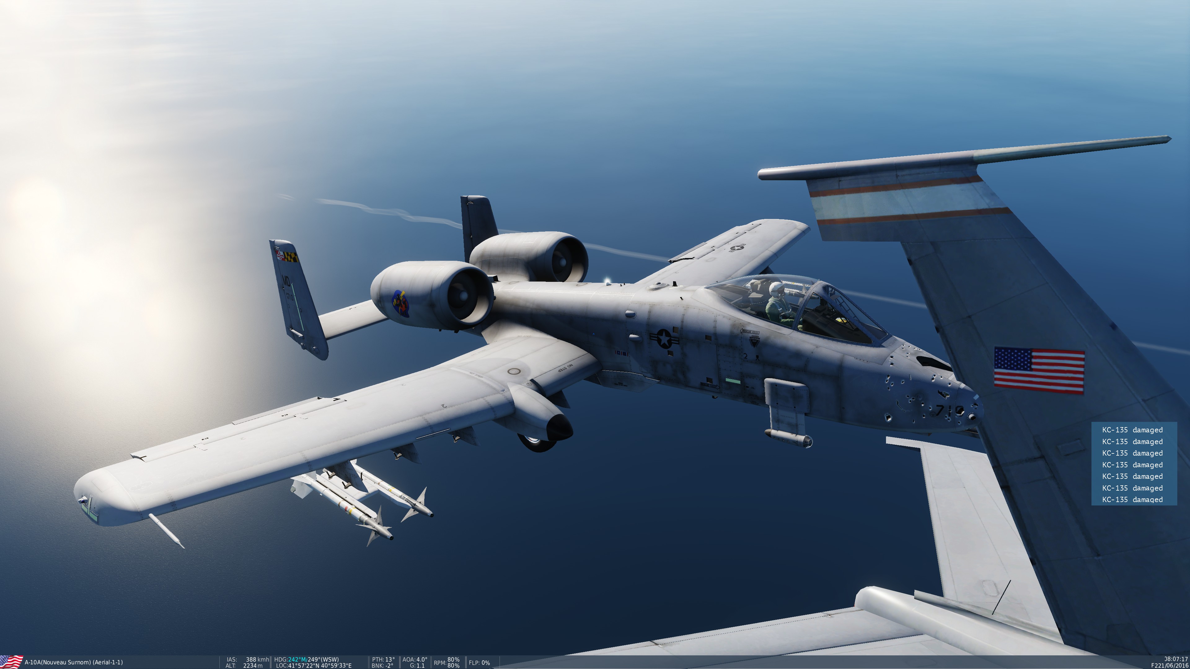
After many years, I'm still not able to do A2A refueling. The best I could get was the endless "return pre-contact".... until yesterday, when I finally got a "cleared for contact". Getting closer and probably too excited about this new milestone, I managed to get my A-10 nose plugged into something for refueling.... but not the right place I guess Maybe someday, I'll get it right. null
2 points
-
Issue has been confirmed and reported thanks2 points
-
I wonder when we will hear something official. I'm honestly surprised there hasn't been a statement yet. Possibly they are waiting for the 2023 and beyond video.2 points
-
And it's fixed internally.2 points
-
@Curly, I have flagged with @Yo-Yo, there is a lot of meat there to review so may take a bit to get a response back. Thanks for your detailed report though.2 points
-
Just ordered my Zotac 4080 along with a Pico 4 - should be interesting to see what performance they bring in flight sims. My current set-up has been good enough to run all sims smoothly in VR, but at half rates (30 or 45 fps - can only run FSX with FlyInside VR at full 120fps with Index) and low-ish settings. I was hoping to upgrade my CPU, but can't be done sensibly - I have an i5 9600k and the only thing I can upgrade to with the Z390D mobo is the i7 9700k - just not worth it. I really don't want to buy a whole new rig just yet. Luckily, I've only had one sim that had my cpu maxed out, and it wasn't DCS World. That may change now - but I should still see a good jump in VR performance, regardless. I'll still have this card when I next upgrade the rest of my rig Anyway, I'll post VR benchmark results with Index, Quest 2 and Pico 4 once I'm all set up. That'll give people with hardware a couple of years old who are thinking of upgrading their graphics card for VR an idea of whether it's worth it or not.2 points
-
Create a Mark via TGP. While doing that, compare TGP coordinates with what popped up on DED. They are different, same in elevation. Then (M-sel) to select that steer, and recall it with TMS-Down(CZ) what TGP slaving to is another coordinate (a new one!). And every time you CZ you get a new jittering one. I think this issue is related to this one. I made a new report because the inconsistency between markpoint recording and TGP coord.display maybe is a different issue. INS_strange_jiggle.trk2 points
-
Update for 2.8.1: Still the same performance drop compared to 2.7.18 Example Beitut 2 -Click from first post: 2.7.18: 74.9 FPS 2.8.0: 65.8 FPS 2.8.1: 66.4 FPS2 points
-
I will get some feedback from the team on this issue. thanks2 points
-
2.5.7 beta https://simshaker.com/software/general/2 points
-
В пилота.2 points
-
There is an option on the weapons page to set whether the laser ranging should use the first or last reflection i.e the closest or the farthes object reflection. Maybe this also helps for designation.2 points
-
It's not an opinion, From the WSPS our huey is AT THE EARLIEST from 1982 Here's the document of them testing it on the huey specifically. But that is irrelevant, as our huey, as per the module's manual, has the composite blades installed. In the second post you see the document for them testing the composite blades, in 1988. Our huey is at the earliest from 1988.
2 points
-
Более вдумчиво полетал, и вот что хочу сказать. Какие-то проблемы у меня вот какого характера: При запуске родного Streaming Assistant, DCS выглядит сильно размыто. Добавление плотности пикселей и прочего особо не дало результатов. Возможно я что-то упустил, однако в свободном полете на кавказе имею ~70Фпс, что вполне вменяемо. Если зайти на онлайн сервер, то фпс проседает, появляются статтеры, однако они редкие и не сильно портят впечатление. Запуск по проводу/без провода, разницы не заметил. Однако как я уже упомянул, изображение сильно мыльное. При запуске через Virtual Desktop картинка гораздо лучше. Даже при плотности пикселей 1.0 - в хорнете вижу даже самые мелкие цифры на MFD. Четкость потрясающая. В свободном полете ФПС лочится на 36, не знаю с чем это связано, однако картинка плавная, все работает идеально. Самую малость видны темные границы по краям обзора, если резко крутануть головой. К сожалению, когда я зашел на сервер в онлайне, начались лютые статтеры/фризы. Буквально каждые 3-5 секунд. При том, что фпс также стабильно держался на 36, это фризы не дают возможности вменяемо летать, постоянно все дергается и залипает на микросекунды. Как с этим бороться, пока не знаю, однако на текущий момент пользоваться PICO 4 для полноценных полетов в DCS у меня не получается.2 points
-
I found the source for the DCS pattern. It's from the North American Aviation Version of the flight Manual. https://app.aircorpslibrary.com/document/viewer/fmp51na5914 The pattern. The DCS pattern is an almost exact fit of this pattern. The NAA manual pattern being the dashed lines. https://www.desmos.com/calculator/2dnjxa31ca It does look like someone from NAA may have miss interpreted the Air Force pattern. As the NAA pattern also mirrors the dispersion pattern. https://www.desmos.com/calculator/ngk08zcyuh And the NAA pattern Disappears from all the documents published after this manual. NAA Harmonization / Convergence Pattern K-14 Sight NAA Manual Azimuth Azimuth Degrees Elevation Elevation Degrees Gun 1 72.5 38.375 0.006623 0.3794699477 0.006348 0.3637136083 Gun 2 82.08823529 36 0.005002764706 0.2866373035 0.007493 0.4293172759 Gun 3 89.125 39 0.005951 0.3409671839 0.005002 0.2865934891
2 points
-
UUUUUUFFFFFFF I am buffed for this one has a cold war era fanatic, I kid you not but I check this post every day I know I am sick but he... you can't deny that this aircraft is a beauty ain't it.2 points
-
At the very least it gets looked at. SMEs will surely be able to answer that. The current implementation is equally just a conjecture as nowhere it says that this function is limited to lau117…all it says is that you need mavs on both wings since it fires one per side and a maximum ripple of 2 missiles total. what i dont get about your statement, why would this be listed in the patchnotes if now we need to bring up evidence to even support the feature YOU listed in the patch as „fixed“, as in what exactly did you fix? It wasnt there before the patch in the first place, how could it possibly have been broken?2 points
-
You outdo yourself every time I check this thread. Looks bombastic!2 points
-
This is only a Visual thing visible in external view. It is not reflected in the flight control display and does not affect aircraft control.2 points
-
Ну воспринимать всерьез обзоры этого парня та ещё затея, у него все новинки офигенные У него и MSFS фантастически работает на 30-40 фпс, всё супер плавно у него Да и Аэро у него просто зашибись работал сразу после выхода. Это просто такой тип позитивного обзорщика, люди такое любят смотреть, таких ещё несколько на вскидку могу назвать на тытрубе. В общем, толку мало от такого, а-ля реакт видео позитивного чувака для тех кто купил или уже решил купить, посидеть посопереживать ему. По факту пока не видел примеров где показывают картинку с фреймтаймами и задержками кабеля - если у кого есть, покажите плиз. Видел таблицу запощенную выше в теме, и там не очень как-то всё.2 points
-
What makes you think the KA-50 is fictional? Designed in the late 70's against the Mi-28 to become the frontline combat helicopter it won hands down in most respects and was operational (I think less than 20 were made though) and did serve in combat operations. It just never "took flight" so to speak until the 2 seat version ka-52 was made (from the body of the ka-50). DCS version of the ka-50 would be a bit of a frakencopter, but the majority of the actual ka-50's were all different from each other as they were more of an ongoing testbed for most of their lives. Again, they did serve in combat operations though.2 points
-
3dsmax_mMbxfIXj80.mp4 HKP Launcher's Highpoly work.2 points
-
I realize the formatting of some of the tables is not ideal. If you wish to read this document in google docs, a link is provided below. The tables can also be viewed from within the spreadsheet. Link to the google doc version of this post. https://docs.google.com/document/d/1LCRhctj31-tdp9ehzIFUILtF0OhItK6ROC2AhEopWXA/edit?usp=sharing Link to spreadsheet. https://docs.google.com/spreadsheets/d/1h3fCvpvdc7j2f3iyASP3ft4ogz3koOjQksYY3i7Bjd8/edit?usp=sharing Ballistic Tables and Ballistic Calculators Firing Tables for many of the bullets used in the war is particularly difficult to find. Especially for aircraft weapons. The aircraft version of the 50 caliber Browning has a 36 inch barrel. Thus has slightly reduced muzzle velocity when compared to the Heavy barrel version of the gun used in ground applications. Therefore, what data is available, for the various 50 caliber ammunition, may not be applicable to an aircraft machine gun. However we can recreate the firing / ballistic tables for various bullets by using the methods and equations from the world war 2 era.. The ballistic tables of this era were computed based on ballistic coefficients and a few different methods of integrating through the appropriate ballistic table. This process is often called the Siacci Method of integration. US military manuals and academic papers of this era indicate the use of Siacci Tables integration methods was the standard process of computing ballistic and firing tables. See The spoiler for examples. The ballistic performance data of the bullets from the World War 2 era is written in terms of a ballistic coefficient. Through the use methods and mathematics of this era, it is possible to create and recreate accurate ballistic and firing tables for the various 50 caliber bullets. Even if the data is lost or missing from the historical record. First, it’s helpful to define the meaning of the term ballistic coefficient. The ballistic coefficient of this era is a way of relating the drag of the bullet in question to an idealized version of a bullet of similar shape. Therefore the ballistic coefficient consists of two variables, a type and a factor. For example in the BRL report. “Ballistic Coefficients of Small Arms Bullets Of Current Production” https://apps.dtic.mil/sti/pdfs/AD0491936.pdf All of the 50 caliber bullets have a type of C5 / G5. While the factor varies 0.414 for the M1 Incendiary to 0.460 for the M2 Ball. We would say the Ballistic Coefficient of the M1 incendiary is C5 / G5 0.414. The projectile type is as important as the factor. As the bullet is matched to a projectile type with a similar drag coefficient. The Equation for the ballistic coefficient as given by Mc Coy is Cj = (mass (lbs)/ form factor (i_j) * diameter (inches)^2) Where j is is of projectile type and the form factor, i, = (CD of projectile) / ( CD of the projectile type.. Ie G5, G6, ect) https://archive.org/details/ModernExteriorBallisticsTheLaunchAndFlightDynamicsOfSymmetricProjectiles2ndEd.R.McCoy/page/n98/mode/1up If we take the weight and form factor data for the M1 incendiary from “Aerodynamic Data for Spinning Projectiles. We can compute the ballistic coefficient of this bullet. Projectile Name: Projectile Weight Grains Projectile Diameter Projectile Type Form Factor M1 Incendiary 625 0.5 5 .86 The first step is to convert the projectile weight from Grains to lbs. We do this by dividing the weight by 7000, which gives us 0.08928 lbs. The ballistic coefficient is then computed as 0.08928 / (.86 * 0.5^2) = 0.41525 Thus the ballistic coefficient of the M1 Incendiary is C5 / G5 0.41525. The test of the production gave a BC of .414 to this same bullet. The ballistic coefficient and form factor are determined either through firing tests or in from a wind tunnel test. The drag of the projectile is then matched to the appropriate projectile type and the ballistic coefficient is determined. The standard Projectile types are G/C 1 through 8. Drag profiles in the for KD are given Hitchcock's work Aerodynamic Data for Spinning Projectiles. https://apps.dtic.mil/sti/pdfs/AD0800469.pdf Pics of both in the spoiler below Data from the BRL on the ballistic coefficients and form factors of a variety of projectiles is readily available. Most of the data is from the World War Two era also. Two of the best sources for this type of data are the reports “Aerodynamic Data for Spinning Projectiles” and “Form Factors of Projectiles”. Excerpts and links to both reports are contained in the spoiler below along with a few other sources. We will use this data to create a ballistic table similar to the ones in the Air Force Manuals of the era. https://www.google.com/books/edition/AF_Manual/81krAQAAMAAJ?hl=en&gbpv=1 We’ll use two methods to create our tables. The full long form of Siacci Method for Flat Fire Trajectories as described by McCoy, Hitchcock and Kent, and a simpler method that was developed specifically by the BRL to produce firing tables for aircraft weapons. The methodology for the Siacci method is described in detail with examples. In Modern Exterior Ballistics https://archive.org/details/ModernExteriorBallisticsTheLaunchAndFlightDynamicsOfSymmetricProjectiles2ndEd.R.McCoy/page/n97/mode/2up?view=theater This method involves looking up data in a table of figures for our bullet type. Then modifying these values based on the ballistic coefficient of the bullet. For example, In the report “Form Factors of Projectiles”. The BRL gives the 50 Caliber M1 Incendiary A ballistic Coefficient of C/G 6 .387. If we assume a muzzle Velocity of 2990 our Siacci operations look a bit like this. By interpolating through the G6 Siacci Table and applying the appropriate equations we are able to compute the bullet drop, the time of flight, and the impact velocity of the bullet at any range. In order to determine the accuracy of this method, Let’s compare a Siacci Calculation for 50 cal AP M2 to the ballistic table in Air Force Manual AFM 335-25 Fighter Weapons. We’ll compare the time of flight and vertical deflection in inches, which is also known as the bullet drop. At sea level with a true air speed of 0 mph. For our Siacci Calculations we’ll set the muzzle velocity to match the chart, 2700 fps, and use the a Ballistic coefficient of C5 / G5 0.458. As this matches the BRL data for a world war 2 version of the M2 AP. In the spoiler below we have the Air Force Firing Table for the 50 Caliber M2 AP. https://www.google.com/books/edition/AF_Manual/81krAQAAMAAJ?hl=en&gbpv=1 I’ve added the Air Force firing table for the 50 Caliber M2 AP to a spreadsheet in order to compare it to the results of the Siacci method of calculating firing tables. Below is the Air Force Firing Table for the 50 cal AP M2 in table form from the spreadsheet. Note that gaps in data reflect those in the actual firing table. In the spoiler below we have A Similar Table with Values computed with the Siacci method. We can also compare the Time of Flight Vs Range of the Air Force Table and the Siacci Method. As this will also give us a sense of the drag coefficient of both bullets. The results of the Siacci table are very similar to the Air Force Firing Tables. The average difference in time of flight between the two firing tables is 0.007 second. Some of the difference being a function of the original tables using a limited number of decimal places. The slight difference between the two data sets, indicates the Siacci Method, when using the appropriate tables, can produce results which effectively match the tables in the primary sources. Thus providing us with a valid means to create ballistic tables for projectiles where no such data exists. While the Siacci method is accurate and flexible. The manual calculations of firing tables using the Siacci method was still very time consuming. During the war the demand for firing tables was at an all time high. Therefore the BRL and the National Defense Research Council (NDRC) developed a faster method to calculate firing tables. The application being primarily limited to aircraft weapons. The method is described in the Report, “NDRC Analytical Studies In Aerial Warfare: “Pages 28 to 30. https://www.loc.gov/resource/gdcmassbookdig.analyticalstudie02bush/?sp=28 The NDRC report provides two derivations of a time flight equation and one equation which computes the vertical deflection / drop of bullet (Q) as function of Time of Flight (t) The short version of the time of flight equation is tof= (range / sqrt v0)/((sqrt(v0)-(((.00186*rho)/bc)*range And the longer version of this equation is tof= (1/((V0/Range)-((k_star*rho)/(2*BC)*Sqrt(v0)) Where k_star = 0.00372 for feet per second Both TOF functions return the same value given the same input. The second version is a bit more flexible as the constant k star can be altered based on the desired unit of measure. The equation for the bullet drop at a given range is given as: Vertical Deflection Feet: Drop = .5*g*t^2*(1-((rho *.00372)/(3*BC))*(Range/(sqrt(V0))) Where v0 = the muzzle velocity + the aircraft velocity in fps Range is the down range distance to the target in feet. Rho is the relative Ballistic Air Density And bc is the C5 ballistic coefficient of the projectile. Thus we come to the major limitation of this equation. It is valid for projectiles with a C5 / G5 ballistic coefficient. Which may not always be the best drag function for a projectile. We’ll circle back to this in the end. For now, let's just compare these equations to the Air Force ballistic / firing table For the 50 Cal AP M2. In the spoiler below is a ballistic / firing table computed using the NDRC method. It is in the same format as the Air Force Firing Table. In the spoiler below is a graph comparing the bullet drop Vs range, aka the trajectory, of the Air Force Table and the trajectory of the bullet we computed via the NDRC method. Along with the time of Vs Range. The NDRC Method actually matches the Air Force Ballistic Table more closely then the Siacci Method. The average difference in time of flight between the NDRC method and Air Force Firing Table is only 0.0052 seconds. The NDRC method also provides an accurate means of computing firing tables. Which shouldn’t be a surprise as according to the NDRC study many of the aircraft ballistic tables of the era were generated with this method. Let's look at one more case. The Aircraft is moving at 300 mph TAS, the density ratio is .6, which corresponds to an altitude of about 15,0000 feet. This altitude was chosen because the density ratio of both the Ballistic and NACA atmospheric models are about the same and it's the altitude for which all the convergence patterns are configured too. In the spoiler We Have the firing table from the Air Force Firing Table and a set of values computed with the NDRC method. In the spoiler below there is a graph comparing the Bullet Drop (Trajectory) and time of flight of the NDRC Method to the Air Force Firing table under the same conditions. On average ,the NDRC method’s time of flight is within .0038 seconds of the chart. Even under flight conditions at altitude, the NDRC method can accurately reproduce the Air Force Firing Tables. Using the Siacci Method we can also compute the trajectory and time of flight under the same conditions. Density Alt .6, TAS 300 MPH. If we overlay all 3 data sets. The results are nearly identical. The marginal differences from the NDRC method, Siacci method and the Air Force Table. May also be the result of some other ways error may have been introduced into the Air Force firing table. These sources of discrepancy may be a result of the earlier version of M2 AP having a higher ballistic coefficient then bullets produced after 1943. If we recompute the ballistic table using the NDRC method and change the BC to .471, to match BRL data for the pre 1943 version of the M2 AP. The average difference in TOF between the NDRC ballistic table and the Air Force firing table. Is the lowest of all the computations presented thus far at 0.002447 second. The same is true for the calculations of the bullet drop. Using a BC of 0.471, the average difference between the NDRC method and the chart is 0.373 inches. These results seem to indicate that the Air Force Ballistic Table for the M2 AP may have been computed for a heavier version of the M2 AP with a slightly higher (better) ballistic coefficient than the production bullets. There may also be some discrepancy between the results due to the fact that a graphic method of interpolation was used in parts of the original Air Force Firing Table. There are also reports from BRL which indicate that the Aberdeen Proving Grounds was having troubles with their measuring equipment .The equipment error caused the institution to issue lower ballistic coefficients to projectiles prior to August 1’st of 1944. Given that the Air Force Firing Table is based on Aberdeen data from prior to August 1’st it’s possible Both the NDRC and Siacci method show good agreement with the Air Force firing tables across a range of circumstances. Therefore, utilizing either the NRDC method with the appropriate ballistic coefficients from period data is a valid way to generate the type of ballistic data needed to implement any of the 50 caliber bullets within DCS. Below is a link to my spreadsheet where I have performed these computations. Most of the work haiving been performed in the Ballistic Calculator tab. Most of the functions and computations should be readable. The idea being that anyone can take a look at the math behind these calculations. There is also a page containing various images and links to the source data. Much of the document however is a work in progress. While parts of the spreadsheet can be useful, it may not be particularly user friendly. It’s easy to mess up a computation. https://docs.google.com/spreadsheets/d/1h3fCvpvdc7j2f3iyASP3ft4ogz3koOjQksYY3i7Bjd8/edit?usp=sharing Thanks for reading this far. I hope this exercise has been insightful as it has been for me. Below are some additional thoughts on the accuracy of these methods. It got a bit longer than I would have hoped, but if you’re interested in this kind of thing you may find it worth reading. As final thought I want to discuss some limitations of approaches presented in this post. While the NDRC function is very useful there are some very real limitations to it. The model is based on the 3/2 drag power law. Meaning below half the muzzle velocity the data becomes unreliable. However there are also very useful ways to use the data generated from the NDRC tables. For example the impact velocity can be computed through a derivation of the 3/2 drag law. Impact Velocity = (Range^2) / (TOF^2) * V0 Which can provide for a more accurate basis of drag coefficient computation. The same information can also be obtained from the Siacci Methods however the process is more tedious. Both the NDRC and Siacci methods may also not be as accurate as more modern numerical techniques. Both methods depend on how well the projectile matches the drag coefficient of its associated type. The war time paper “Ballistic Coefficients of Small Arms Bullets Of Current Production” https://apps.dtic.mil/sti/pdfs/AD0491936.pdf Assigned almost every projectile a C5 / G5 ballistic coefficient. A few years after the war, the projectile types and form factors of some of the more common 50 caliber bullets changed. The M1 incendiary goes from a G5 0.414 in 1944 to a G6 0.387 in 1951. If we compute the impact velocity for both bullets with the Siacci method, On average the G6 0.0387 version impacts 35 to 45 fps faster than the G5 0.414 Ballistic coefficient. Which indicates that the BRL thought the C5 / G5 ballistic coefficient resulted in to much drag. In the spoiler below is chart comparing the impact Velocity Vs Range of the M1 incendiary with both ballistic coefficients. The story is similar for the M8 API, which is considered one of the most effective 50 caliber bullets. During the course of the War the bullet was given 3 different G5 ballistic coefficients. None of the G5 ballistic coefficients were accurate enough as there was considerable variation in the form factor as function of mach. Thus a custom drag function / bullet type was created for the M8 API. Image of custom drag function and conversion to modern CD notation in spoiler A set of Siacci tables was created for the M8 drag function. There A 1996 report by the BRL indicates that the CDO of the M8 drag function is 4% lower in the supersonic regime. However examining data in detail also raises some questions. Plotting the old drag function on top of the 1996 data, shows that the old drag function actually has a higher supersonic drag coefficient than the author says. It is possible to match the data by reducing the old drag profile by 4% though. Given total drag on the projectile is a function of the CD0, the quadratic yaw drag coefficient and the angle of attack of the bullet. McCoy’s plot of CDO does not represent the total drag coefficient of the bullet in flight. The older drag function however computes the drag as a function of trajectory angle. Which may provide a more accurate assessment of the total drag on the M8 API during flight condtions. A comparison of both methods would require a full 6 dof simulation with McCoy’s data and a similar calculation using the Siacci Tables for the M8. However both sets of data would need to be checked against some type of test data. The best set of data publicly available are either the Air Force Firing tables, or the 1946 copy of the M8 firing table for the heavy barrel machine gun. Which puts us back to square 1. This has led to some reluctance on my part to take the time to implement M8 Siacci Tables into my spreadsheet. It’s a lot of data entry and I’ve already spent way too much time on this. The World 2 Data G5 data is probably accurate enough for the purpose of video games.2 points
-
Muzzle Velocity Part 2: More Data. There is also some secondary data on muzzle velocity that also agrees with the numbers provided in my first post. We’ll consider some indirect evidence, particularly what is known as Instrument Velocity. Along with the methods that were used within the War and post war era to compute muzzle velocity. In many of the source documents bullet velocity values are given at a specific distance. From the Small Arms Development Report for example. The velocity of the M2 AP from a 36 inch barrel at 78 feet is 2810 +- 30 fps. https://archive.smallarmsreview.com/archive/detail.arc.entry.cfm?arcid=13268 The Ballistic Research Laboratory (BRL) calls the bullet velocity at 78 feet, the instrument velocity. Ballistic Coefficients of Small Arms in Production 1944 https://apps.dtic.mil/sti/pdfs/AD0491936.pdf The standard setup used by the BRL was to place the first chronograph 28 feet from the barrel, and the second 128 feet from the barrel. Thus the distance from the midpoint of the chronographs was 78 feet and the chronographs were 100 feet apart. This paper also gives us 2 equations to compute the muzzle velocity from the instrument velocity. Muzzle Velocity V0^.5 = v^.5 + (.059 rho/C5 Ballistic Coefficient)*Distance(78* 0.5) We can simplify this a bit and just get the muzzle velocity by squaring the right side of the equation. Muzzle Velocity = (Instrument Velocity ^.5 +((.059 * 0.07513/ Ballistic Coefficient) * ( 78 *05))^2. Note, that rho is the ballistic sea level air density in lbs per foot^2. The report also gives us this equation. The muzzle velocity - the instrument velocity = 4.3* (78^2/1000) Mathematically this formula tells us to add about 26 fps to the instrument velocity. For example the instrument velocity of the .50 caliber M2 AP is given as 2810 fps. The muzzle velocity is 2836 fps. Which is the figure quoted in many of the post 1944 reports. Such as the 1945 version of manual “Terminal Ballistics Data”. https://cgsc.contentdm.oclc.org/digital/collection/p4013coll8/id/2373/rec/8 There is yet another way we can compute the muzzle velocity from instrument velocity. Since we have the ballistic coefficients of these bullets it’s possible to work backwards through the Siacci tables and compute the muzzle velocity. I’ll spare you the details of integration of the Siacci tables. However the approach is validated within Ballistic Coefficients of Small Arms in Production 1944, and by McCoy in Modern Exterior Ballistics. https://apps.dtic.mil/sti/pdfs/AD0491936.pdf So let's apply our 3 equations to compute the muzzle velocity from the Instrument Velocity. Then will compare the results to the values given in th 19. Well use ballistic coefficients given in 1944 report, The Instrument velocities from the Ordendance Department’s Small Arms Development Report and the post war report Form Factor of Projectiles BRL Report 564 1951. Value: M2 AP API M8 M1 Incendiary BC C5 0.458 0.439 0.414 Instrument Velocity at 78 Feet 2810 2910 2950 Instrument Velocity At 78 Feet: mps 856.446 886.925 899.116 Muzzle Velocity BRL C5 Method 2850.160 2952.641 2995.534 Instrument Velocity + 26 fps 2836 2946 2976 Muzzle Velocity Siacci 2843.341 2945.325 2987.641 Muzzle Velocity 50 Cal Manual 1946 2840 2950 2990 All three methods used to compute the muzzle velocity from the instrument velocity show good agreement with the muzzle velocity cited in various source materials. This all just amounts to another piece of evidence indicating that muzzle velocities for the 50 calibers in game are a bit too low. Data Sources and links in the spoiler2 points
-
Thank you for the kind words and feedback.2 points
-
Seeing the first in game screenshots of the F-4 will for me be like receiving nudes from a chick after being on a military deployment for six months (people who have been deployed will understand).2 points


-
Recently Browsing 0 members
- No registered users viewing this page.