Search the Community
Showing results for tags 'flight model'.
Found 22 results
-
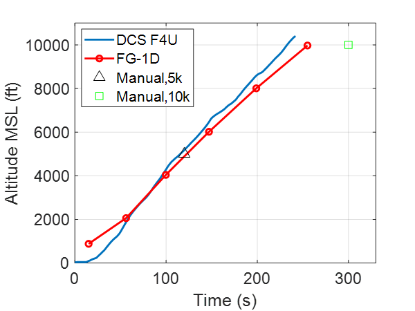
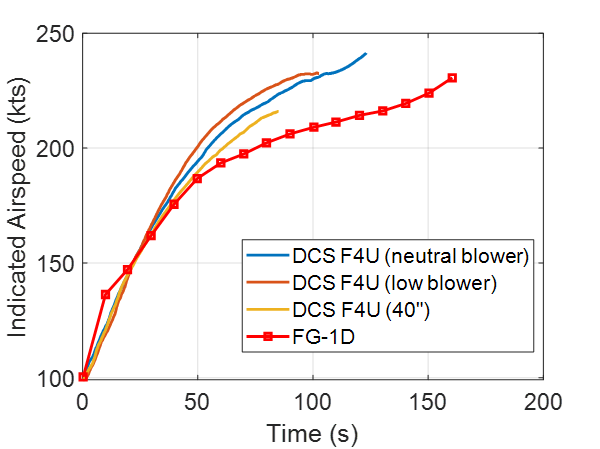
I was quite excited by the new F4U but have heard some criticism of the flight model and engine power. So, I wanted to take a closer look to see how it compares to both the quantitative and qualitative metrics published in the wonderful article entitled “Ending the Argument” by John M. Ellis III and Christopher A. Wheal, published in EAA Sport Aviation, June 1990. Now, for the caveats… The article was a pseudo-controlled experimental flight-test designed to evaluate performance differences between the FG-1D Corsair, P-47D Thunderbolt, F6F-5 Hellcat, and P-51D Mustang. I know we do not have a true representation of the FG-1D, however the engine (R-2800-8) and airframes are close enough for my lackluster piloting skills. Interestingly, it also had two stores pylon installed for the flight tests. Airframe and engine stresses were limited owing to the age of the airframes and using 100LL fuel. This effectively limited the Corsair to Maximum Except for Takeoff (METO). I used 55” of manifold pressure, which is likely too high, but at least my assumptions have been documented. The engine was officially rated for 2000 BHP as in the DCS model. Superchargers were limited to low-blower, and altitudes to 10,000 ft. This makes a difference as I will demonstrate. CG was located at ¾ aft, and there was no mention of fuel load. I selected ½ tanks but will likely revisit my data with another series of tests at full fuel. I removed all ammunition weight as the test aircraft had dummy 50 cals, but no ballast ammo (near as I can tell). My controls setup uses a curve of 25 on all axes, and a 70% saturation on the rudder deflection. I performed some tests multiple times when I suspected higher variance due to my shoddy pilot skills. That being said, I did not perform detailed error analysis on the data presented herein. I welcome others to try the tests and post your results. On to the data… Test 1: Takeoff distance: As per the manual, takeoff distance for the aircraft at 11,000 lbs is approximately 900 ft at sea level, and 1,300 ft over a 50 ft obstacle in no-wind conditions. I won’t say much here other than my takeoffs were all around 1,200-1,300 ft, which I am certain is dominated by inferior pilot skill on my part. The test pilots note a takeoff roll of 1,200 ft at METO power, which is more or less in line with my tests. Test 2: Climb Performance: I will not reprint the graphs from the article as I want to ensure full credit to the original authors and not run afoul of copyright concerns. However, I have used plot digitizer to extract relevant FG-1D data for comparison to our DCS model. The first test is a time-to-climb test, started from the runway up to 10,000 ft. The flight was conducted at full METO power with a climb speed of 135 kts, takeoff weight of 11,055 lbs, and surface temperature of 77 F (as per Table 1 in the article). The figure below shows the time history of MSL altitude for the FG-1D, DCS F4U, and two data points from the F4U-1D manual corresponding to full Mil-Power climbs to 5,000 and 10,000 ft. How I did it: I started on the runway with 50% fuel and executed a standard takeoff. I reduced power to full METO power which was giving ~55 in of manifold pressure @ 2700 RPM. I trimmed the aircraft for 135 kts which required substantial trimming on all axes. The remainder of the flight was relatively hands off, only requiring small corrections to attitude to maintain airspeed. I put the mixture into auto-lean as per the flight manual, and did not engage the blower. Discussion: First off, the flight data presented in the report starts at ~1,000 ft MSL with no discussion of initial conditions. I time aligned my data to overlap the altitude at ~2,000 ft MSL to discount the takeoff and trim transients. After this point, there is a slight climb-gradient difference between the DCS and FG-1D aircraft, however it may be within the test margin of error with time-to-climb difference of 15 seconds. In the article, the Corsair, Thunderbolt, and Mustang were all tightly grouped, with the Hellcat outperforming all by nearly 30 seconds. So, in this case our data would group more closely with the F4U/P47/P51 as it should. The flight test and DCS data align well with the manual to 5,000 ft, however the 10,000 ft mark is quite offset, requiring another 50 seconds of climb. I suspect this is related to the weight of the aircraft and will repeat the tests with full fuel when able. Test 3: Level Accelerations: This is one of my favorite flight test maneuvers as it requires some pilot skill (yikes) and tells you quite a bit about the power and drag characteristics of the aircraft. In brief, the test starts at 10,000 ft and pattern speed, which is ~100 kts in the Corsair in the clean configuration. Full METO power is smoothly applied, and every attempt is made to maintain a constant altitude. The time history of airspeed is logged and is an indicator of excess power from the engine. Flying this test in the Corsair is a real challenge owing to the massive change in trim and quick dance on the rudder pedals necessary to maintain straight, coordinated flight during the maneuver. How I did it: I matched the flight test OAT at 50 F, and started straight and level at 10,000 ft. (I actually began the flight at closer to 150 kts and decelerated to 100 kts without retrimming, which makes the initial acceleration easier to deal with as you only need relieve pressure on the controls to maintain straight and level flight.) I repeated the test three times, once with the blower in neutral, another with the blower in low, and the final test with the manifold pressure limited to 40 in. Discussion: The plot below shows the time history of indicated airspeed for the FG-1D, and three tests corresponding to METO neutral, METO low blower, and 40 in. of manifold pressure settings. The low blower allowed for close to 60 in. of manifold pressure at 10,000 ft, whereas the neutral blower case was closer to ~45 in. Clearly none of the test cases capture the flight test data of the FG-1D, indicating a mismatch in the excess power (Thrust*V_inf-Drag*V_inf). I cannot comment on the sea-level max airspeed debate, but as far as this test confirms, the engine thrust (I said thrust, not power) seems to overpredict the measured performance data of the FG-1D. I.E. the velocity scaling seems to be off, allowing for higher accelerations that would otherwise be possible while still achieving roughly the same top-end speed. I suspect this is due to incorrectly predicting the slope of the C_T vs advance ratio curve at low – medium advance ratios or perhaps a lower induced drag from the airframe. Test 4: Stalls Power on and off stall characteristics were evaluated at 10,000 ft in the clean and dirty configurations (gear, 40 deg flaps). Slow deceleration rates on the order of 3 kts/s were used, though the flight tests were conducted with an even lower gradient of 1 kt/s. Test data in the table below indicates reasonable agreement except for the power-off, clean configuration. In this case, repeated tests were conducted to verify that the aircraft does stall repeatably at a much lower airspeed than the flight test aircraft. This could be due to a mismatch in vehicle weights, but similar tests conducted with full fuel will need to be performed to comment further. Stall performance FG-1D DCS F4U Power off (clean) 85 kts 74 kts Power on (clean) 76 kts 74 kts Power off (dirty) 69 kts 75 kts Power on (dirty) 55 kts 55 kts Qualitatively, the test pilots noted that the FG-1D had no propensity to drop a wing in either direction, favoring instead any turn towards the uncoordinated slip direction (slow wing). In my testing, I attempted to initiate stalls to either side and was unsuccessful in getting the right wing to drop. Asymmetric stall is a complicated aerodynamic phenomenon, but it appears the propeller torque dominates for the DCS module. Test pilots noted that there was little stall warning, perhaps only a few knots with light buffet. In a simulator this can be the best indication of impending stall, even if it’s slightly overdone (Tomcat anyone?). They did note a peculiarity with the Corsair in that the stick force gradient gets very light approaching stall, which would/will be fun when we all get force feedback joysticks! Test 5: Static Lateral-Directional Stability This test sheds light on the rudder authority in a steady, wings-level sideslip. The test pilots noted that the Corsair’s rudder control was extremely heavy compared to the other aircraft tested. Between 180-190 kts, the aircraft required ~50-60% aileron deflection to maintain level flight. In the landing configuration with full flaps and gear, ~20-50%. This wide margin corresponds to the increased influence of the engine torque and spiraling slipstream from the propeller at lower airspeeds. The test pilots noted a peculiarity with the Corsair in that, “The Corsair's only response to left rudder in either configuration as to drop its nose, suggesting weak or non-existent dihedral effect with right sideslip.” How I did it: This one is pretty straight forward. Trim for 180-190 kts at 10,000 ft, then smoothly apply full rudder control. Estimate aileron deflection necessary to maintain zero turn rate as measured by the slip/skid indicator. I repeated this several times in both the left/right directions and at lower airspeeds ~100 kts with full flaps and landing gear extended. Again, all flights were at 50% fuel and no ordinance. Discussion: At airspeeds between 180-190 kts, the aileron deflection is on par with the 50-60% noted by the test pilots, indicating that the rudder authority at higher airspeed is about correct with the 70% saturation limit (first figure below). At lower airspeeds, the aircraft requires almost the same level of aileron control (second figure below), indicating that the rudder control derivatives do not have the correct velocity scaling or the influence of the prop slipstream is not correctly captured. This is certainly an area where the flight model could be improved. Additionally, I think there’s an opportunity to add in the Corsair quirk of little roll with left rudder and nose drop as the current model is quite symmetric (albeit maybe somewhat visible in the bottom left plot). Figure: Full left rudder (left) and right rudder (right) with ~50-60% aileron deflection. High-speed condition, 190 kts, 10,000 ft, 50% fuel. Figure: Full left rudder (left) and right rudder (right) with ~50-60% aileron deflection. Landing configuration (gear + flaps 40), 110 kts, 10,000 ft, 50% fuel. Test 6: Roll Performance Full left/right aileron deflections were used to assess roll rates for a 1-G, full 360 deg roll. As with most other tests, this one was flown at 10,000 ft, and ~200-220 kts indicated. This test was also repeated in the landing configuration at ~100 kts with full flaps and landing gear deployed. Obviously, a full 360 deg roll would be inappropriate with full flaps and gear, so the test was terminated at 90 deg of bank. At high speed, the aircraft needed full continuous power, and only ~28” manifold pressure in the landing configuration. A follow-on test of “rolling under G” was performed by executing the same high-speed maneuver with a steady 3-G load on the airframe (sort of a barrel roll I guess). The pilot reports indicate a significant reduction in roll performance under load with the Corsair giving up ~26-38% of its 1-G roll rate. Of note, these tests involved a 180 deg roll, not the full 360 used for 1-G testing. Data for all tests used the time to perform the complete roll in lieu of instantaneous roll rate data which is often much higher. Discussion: The table below highlights the difference in roll rates at high and low speed for the FG-1D and DCS F4U. Measured roll rates for the DCS F4U align reasonably well at high speed for the left-hand rolls. However, as is obvious from the data, the right-hand turning capability is off the mark. Low speed performance is symmetric, but slow. This again is a straightforward fix in the flight model, and I hope it makes its way into the next update. The accelerated data should be taken with a massive grain of salt as it is quite pilot dependent and holding a 3G turn without using your bottom as a G-indicator is difficult to say the least. I would appreciate community feedback on your numbers for this maneuver. Roll Performance FG-1D DCS F4U Right (high speed) 4.5 s (81 deg/s) 5.4 s (66 deg/s) Left (high speed) 4.9 s (73 deg/s) 5.1 s (70 deg/s) Right (low speed) 2.3-4 s (38 deg/s) 2.9 s (31 deg/s) Left (low speed) 2.3-4 s (38 deg/s) 2.8 s (32 deg/s) Right 180 deg (3G high speed) 3.1 s (58 deg/s) 6.1s (30 deg/s) Left 180 deg (3G high speed) 3.7 s (49 deg/s) 5.4s (33 deg/s) Test 7: Dynamic Stability I’ve seen quite a bit of chatter about the rudder authority and “wagging” (aka Dutch roll) of the F4U online, so I was particularly interested in assessing the directional dynamic response. Pilot reports indicate that all aircraft were deadbeat (aka, no overshoot) in the roll and pitch axes, and that the Corsair was notable for its pronounced Dutch roll. How I did it: Dynamic stability tests should be made with relatively small control inputs so as not to significantly alter the aircraft’s speed or altitude. I used either singlets (rapid fore/aft or side) motions to induce oscillations and noted any overshoot in the short-period, or oscillation in the long-period modes. Discussion: The pitch and roll axes were well behaved with little overshoot and no noticeable oscillation. The pitch axis is quite sensitive, but pilot reports indicate that it had the lightest control force gradient (stick force per G) of all aircraft tested. I cannot really say for sure, but it’s plausible that we need to fly it more like an Extra 300 and less like a P-47, so go light on the controls. Perhaps. The rudder control, on the other hand, does show substantially lower damping than indicated by the test pilots. They noted the worst case was three overshoots before the oscillation was damped. In my tests, I was routinely experiencing 6-8 (see plot below) with corresponding lower amplitude, but higher damping oscillations in roll. Again, from a flight model perspective this is a relatively easy fix (C_N_β anyone?), so I hope it too is incorporated in future updates. Test 8: Dive Test This test can also give some indication of the excess power/drag behavior of the aircraft, and how much trim control is necessary to compensate for speed buildup. This test is initiated at 10,000 ft MSL and ~100 kts, followed by a -1G pushover to a 30 deg dive and applying full METO power. Recovery is initiated at 5,000 ft noting the max speed at pullout. The pilot reports indicate that the Corsair had high rudder forces requiring retrimming during the dive. Discussion: From the table below, the DCS F4U is not far off the mark in the dive test. Starting at 100 kts, it matched the test aircraft to within 7 kts passing through 5,000 ft. Of note, my dive angle was slightly higher with an average of ~34 deg. I used the gunsight to estimate the angle, but precise control is tricky without some sort of digital readout. Of note, the aircraft does require increased rudder deflection as the speed builds and is relatively easy to trim as indicated by the pilot reports. This indicates again that the excess power and drag characteristics of the airframe are mismatched as the dive time is significantly faster than the measured data. As with the level acceleration, this seems to point to a mischaracterization of the thrust and/or drag at low to medium speeds. That being said, the required rudder trim at different airspeeds is probably correctly modeled. Dive Test FG-1D DCS F4U Start Speed 100 kts 100 kts Max Speed 348 kts 341 kts Time 32 sec 23 sec Conclusion: In summary, I think we have a wonderful start at one of my favorite aircraft. I hope Magnitude 3 will continue to develop the module and address some of the flight model issues that make the Corsair unique and a challenge to extract maximum performance. Specifically, I see the following issues that could use a bit of tweaking: Takeoff: Find a better pilot . Climbs: Reasonable agreement, engine power may be slightly overpredicted Level Accelerations: Tune the low-medium speed thrust and drag model to better approximate measured accelerations. Stalls: Uncoordinated stalls seem to always break left; this should not happen. Clean, power-off stall is too slow. Static Directional Stability: Low-speed rudder sensitivity too high, high-speed just about right with 70% saturation. Incorporate Corsair pitch quirk with left rudder and tune roll coupling. Roll: Resolve the left/right disparity in roll performance. Dynamic Stability: Directional damping needs to be increased to match the three-overshoot oscillation noted in flight test. Dive Test: As noted with the level accelerations, tuning of the thrust and drag models are needed to better match available data. I would like to repeat many of these tests with full fuel to further explore the flight model and ascertain if any of the noted discrepancies persist in a heavier configuration. I am also exploring sustained and instantaneous turn data, but it is somewhat complicated by scatter and self-imposed structural limits in the flight test data. I would greatly appreciate any constructive feedback and additional references that may have been used in developing the flight model to augment this analysis.

-
 After over a year of refinement, trial and error and learning from other flight model projects, I present to you the successor to my previous FM project. Basic External Flight Model (EFM) template! This is an enhanced version of the EFM template provided by Eagle Dynamics, with emphasis on simplicity and editability while also feeling smooth and believable. This FM template was designed to work "out of the box", designed like a two-engine subsonic trainer/fighter. What is included: Lift, drag, side, and thrust forces. Axis and discrete (keyboard) pitch, roll, and yaw controls with trim. Landing gear, flaps, slats, and air brakes. Engine startup/shutdown. Basic fuel draining system. Basic damage mechanics. Semi-realistic stalling, Dutch-rolling, and other oscillations. Infinite fuel and easy flight options. Example parameter to interface with the Lua environment. Lots of comments explaining how things work. The template itself and a pre-built .DLL file can be found on GitHub! https://github.com/IGServal/DCS-Basic-EFM-Template Here is a pre-built .DLL with instructions on getting it integrated in a mod: BasicEFM mod.zip Requirements: Microsoft Visual Studio (2019 was used to create this, but other versions might work as well). Basic understanding of C++, Lua, and flight physics. Feedback, bug reports, and suggestions are always appreciated!
- 44 replies
-
- 8
-

-

-
- flight model
- efm
- (and 1 more)
-
Hi everyone, Small issue, with the late January update, the 9M38M1 as fired by the Buk-M1 rolls to turn. While I don't know if the 9M38M1 actually does, rolling to turn would be quite unusual given its conventional cruciform layout (a layout it shares with most missiles in-game) - it's the only missile with a cruciform layout in-game that does so - no other missile with the same configuration exhibits this behavior and the only missiles in-game that do, are missiles with prominent wings (such as cruise and certain gliding munitions like the JSOW) where rolling to turn is expected. The only SAMs IRL that I'm aware of that roll to turn are the British Thunderbird and Bloodhound SAMs, which don't feature in DCS. 9M38M1_roll2turn.trk
-
Hi everyone, I've noticed that the HQ-16 SAM is behaving quite oddly: After burnout has occured, so long as the missile is unloaded, it will continue to accelerate (even in a climb). The HHQ-9 missile also suffers from this issue, though to an even more extreme degree. The missile continues to climb despite aiming downwards, even at fairly significant pitch angles (in excess of 15° below the horizon, even its rocket engine still firing). HQ-16_HPJ12_bug.trk
-
Hi there, my question is kinda self-explanatory. I am a bit out of the loop regarding the F-16 flight model improvements. I believe there were *some* adjustments made in the second half of 2021, though I do not remember how significant those were. So, are more changes to the FM to be expected in 2022 or does ED consider the work on the F-16's FM to be fully complete by now? I am asking because I was surprised of how easily every single modern jet manages to get on my 6 in both 1 and 2 circle dogfights. I know the Viper is considered to be a great ratefighter (2C) and I *think* I am doing everything right, especially maintaining my speed, around 420-440kn in a sustained turn, yet I get killed over and over. I am by no means the best dogfighter, but frankly, neither are my friends, yet I always end up on the losing side whenever they get inside something different than an F-16. This is why I decided to ask here, hoping that someone more experienced would clear things up, as well as getting some info on the state of the Viper's flight model accuracy. Any feedback is appreciated!
-
When I do researches on F-5E tiger's Landing video records, I found most of the "tigers" will do a nose up Aerodynamic Braking, in this video the voice over said 10 degrees (?) But I found it's really hard to do it in DCS, even I tried to touch down very Gently, the nose gear will "Strike to the floor" within 2 seconds, just like there is a force that pulling it down. ( I double/hundred checked my brakes are off ),TRACK INCLUDED DOWN BELOW , but yet I'm not a professional, and I'm lack of documents to proof it further, maybe you the one can provide a little help. PS. the F-5E must need moooooore LOVE F5LAND.trk
- 18 replies
-
- 8
-
-
- f5e
- aerodynamics
- (and 6 more)
-
 patches 2.7.4.9632 and 2.7.4.9847 have introduced various fixes and tweaks to controls, trim and FM. And for the most part they seem to have been very sucessfull (fe the problem with "overtrim" are far less and the sound feedback is also very helpfull). The Shaitan-Arba is now also much more controllable at low speeds. Especially noteworty in a positive way - VRS does no longer suddenly and fatally happen, the soundmapping for RBS, VRS, max-envelope aso is now a completely suitable indicator. What seems to need further attention is the following though: the feel of weight and mass now seems reduced, and the Hind is too twitchy in various envelopes (to the point where one seems to "stir" the cyclic aka the joystick) while hover transitions are now far more controllable the hover itself seems to have become very twitchy even in low-weight and zero stress conditions the wheels now "soapglide" even more in almost all terrains, even with collective on zero, rpm throttle down, and wheel brakes locked I have included a track from the remastered-for-hind huey-campaign (ty for that excellent scenario to really control the Hind @Bailey) where this can be seen. I also could directly compare the asset behaviour to before the patch (as I had just flown that mission before both patches). Twitchy hover: during takeoff at final landing at "Madrid" at the end "soapgliding" of wheels at rolling landing and taxi at Senaki-Kholki on the pad at "Madrid", with various test of AP channels, locked wheel brakes, applied wheel brakes, idle rpm, zero collective, diverse trimstates "rudder" (tailrotor), "heading" AP channel on/off slights osciallations during flight in stable envelope with no input entire flight various attitudes, crabbing during transition during speed hook or forward reduction notice zero control input (control input indicator up entire track) notice "pulse" inducing oscillation with slightest inputs as if input signal is registering on/off For the problems describe above, also notice how for the most part non-pilot induced oscillations seem rock stable while any attemopt to correct them with minor cylic, minor collective or general slight(test) peripheral input seem to surge the oscialltions or the twitchy hover behaviour (especially noticeable at the end of the track, when I almost crash myself at "Madrid"). The widely reported "overtrim" or "input overshoot when pressing trim" is reduced but still noticeable. For the passer-in-glancing, please focus on the bug behaviour, my bad flying is a given having to be seen as "baseline" . Trackfile as google-drive link as filesize exceeds attachment limit: https://drive.google.com/file/d/1u71lvSaImScYA2f3zgynpGPhEwe5roFX/view?usp=sharing Dxdiag file attached for good measure. DxDiag.txt
 -
My experience is with the P-51D but probably applies to all the tailwheels. I would like to see DCS improve the flight model particularly for when the plane is on the runway both taking off and landing. The plane does wild yaws that are very unrealistic. I understand about torque and ground loops and such but planes don't travel down the runway sideways in real life. The amount that the plane can yaw before it stalls or has a wing strike needs to be more limited.
- 51 replies
-
- 1
-
-
- ground loop
- yaw
- (and 2 more)
-
At some point in 2020, an update came along and made FC3 FM stuff encrypted, so now modders have to either create their own flight model (If you have a guide or tutorial to help do that, that would be great); or resort to the default "nil" flight model, which is called SFM? This flight model is terrible. It just feels to sticky, jittery, awkward and disorienting (especially in VR). Dogfights are just awkward and pretty much impossible (for me) without invulnerability. I made a video that attempts to show some of this weird behaviour especially with rolling, stalling, and high angle-of-attack maneuvers. The only mod I've seen with a custom flight model is Freebirddz' pretty good Su-30 mod, available here: If the embedded video doesn't work, here's the link: https://youtu.be/ICSDFUNydQo If would be great if Eagle Dynamics would improve this default flight model or provide documentation or guides for creating a custom flight model. Both would be fantastic. (side note: I'm experimenting with the creation of a custom flight model. If you got any ideas, feel free to share on this forum post of mine: https://forums.eagle.ru/topic/264171-are-there-any-guides-or-tutorials-for-making-a-custom-flight-model/?tab=comments#comment-4588513 )
-
I'm experimenting with the creation of a custom flight model. I got the FM template, but I can't find any tutorials or guides on how to implement all the functions into DCS. By "functions" I mostly mean engine control (throttle), landing gear, flaps, etc. However, pitch, roll, and yaw with trimming work just fine out of the box.
-
After several months of trial and error and learning from other flight model projects, I present to you: Serval's custom Flight Model mod! Credit goes to CptSmiley for creating the prototype F-16 FM that I edited to make this. You can find that here: What is this mod? Every player-controlled aircraft in DCS needs a flight model (FM) along with it. For a while, modders used the FMs from Flaming Cliffs 3 (FC3) aircraft for their mods. At some point last year, an update came along that made those files encrypted, leaving modders with the terrible default FM. The idea behind this mod was to create a flight model that imitates the Su-27/33 "game" flight mode behaviour used along with FC3 style cockpits for unofficial, community-made mods; as a replacement for the awkward and jittery default flight model (I seem to be one of a few people to notice how awful it is. see this post of mine for a demonstration of it: https://forums.eagle.ru/topic/264462-default-flight-model-is-awful-with-video-demonstration/?tab=comments#comment-4591944 ) I am not a programmer or aerodynamics expert; so I apologize if anything looks weird. Now, before I share the files, please read the following warning: DO NOT USE THIS MOD TO FLY OFFICIAL AIRCRAFT. BUY THE MODULES AND SUPPORT THE DEVELOPERS! The files can be found here: CustomFM mod v7.zip Here's the source code. It may take some time for me to update this after the main mod. Now you can fly smoothly without awkward jittering at high angles of attack! Have fun! Be sure to check the follow the instructions in the .README file and give feedback if you have any! Here's a few things that are still in the works: - Cockpit controls; as of now the stick, throttle, and rudder pedals don't move at all despite input. - Engine startup behaviour. - Autopilot. If you wish to integrate this into a mod and redistribute it, go ahead but please give credit to me and Cpt.Smiley. If you wish to modify the source code and re-release it under your name, you may do so; but again, please give credit. Version 2 changes: + Improved engine on/off logic. + Idle RPM is now 50% instead of 25%, afterburners now ignite at ~92% instead of ~85%. + Control surfaces now move smoothly. + Flaps (for aircraft that have them). + Digital or "keyboard" pitch and roll controls are faster. + Improved FBW stability and anti-stall logic, death spirals are now a lot less likely to happen. + Behaviour on the ground is now a bit more realistic, it now takes a bit longer to achieve takeoff speed (~300 Km/h). Version 3 changes: + Improved ground handling. + Smoother FBW stability. + Tail hook functionality (for planes that have one). + More realistic flap and air brake aerodynamics. Version 4 changes: + Reworked stability system, much improved dogfighting performance. + Improved afterburner thrust. + Corrected wheel positions and springs. + Cleaned up the source code, including more comments. Version 5 changes: + Autopilot! Sadly, no route-following mode (yet). + Damage modeling. Wings, tail, and engines have their own effects on flight behaviour when damaged. + Using wheel brakes no longer leaves skid marks. Version 6 changes: + Smooth engine startup and shutdown (at last!) + Slightly tweaked autopilot. + Stability system now behaves a bit more like the Mirage-2000 and MiG-29. + Controls are a bit more responsive, especially downwards pitch. + Pitch trim is slightly faster. + Flaps generate a bit more lift. + Fixed a bug where altitude and roll hold autopilot doesn't reset when restarting a mission. + Damage modeling has been tweaked and made (somewhat) more advanced. Version 7 changes: + Much stall recovery and post-stall behaviour, unrecoverable spins are pretty much impossible now. + Better analog roll control. + Slightly tweaked damage stuff. (ps: this is the first mod I have ever published!)
- 53 replies
-
- 7
-
-
-
- flightmodel
- fm
- (and 1 more)
-
 All charts are sourced from SFI AJ 37 del 3, 1979 print. Test flights were flown in ISA, using weights as close as possible to those described for each loadout (remembering that the AJS is somewhat heavier than the AJ), either start weight or flight weight depending on what the chart in question described. LEVEL ACCELERATION Tests were run at 0km, 6km, and 11km in ISA conditions only. Each test included two runs (one by myself, one by Airhunter) with clean config/rent FPL. In addition, I ran a second set of 0km tests with a group 3 loadout (4x ARAK + XT), and 6km tests with a group 4 loadout (4x SB + XT). Two tests were run at 11km with the loadout stipulated in the manual, one by myself and one by Airhunter. Airhunter provided me with tacview files and graphs which I then charted against the manual (obviously only for the clean config 0km and 6km tests, and the 11km test). On my own end I forgot to save tacviews, but did save trackfiles, which are attached as well. The results show what I'd found myself: At sea level, mil thrust is maybe a touch slow to accelerate to M 0.9 but is still relatively close, and zone 3 is tuned almost on the dot. Zone 1 and 2 show discrepancies, particularly zone 1, although they aren't very large at this altitude. Excuse the rather unscientific graphs, but unfortunately just overlaying the ones from tacview wasn't really workable and I'm working with what I've got here: At 6km alt, mil thrust gradually diverges from the chart, ending up a little slower than expected. Zone 1 and 2 show large discrepancies. Zone 1 follows zone 2's curve, zone 2 follows zone 3's curve, and zone 3 is doing something else entirely. At 11km alt, only zone 3 was tested. The results were very far off the expectation: according to the chart, level acceleration from M 0.9 to M 1.6 should take about 5 minutes and 45 seconds. In the sim, this was achieved in just one minute (!), while acceleration from M 0.9 to M ~1.63 (as far as the line is drawn) should take about 7 minutes and 15 seconds, while in DCS it took 1 minute and 15 seconds. This is a very large discrepancy even compared to the aircraft's own charts, but also compared to acceleration profiles of other aircraft known to have phenomenal performance in this area (F-104, MiG-23, MiG-29). Something is clearly causing an issue here but I don't know what. Big thanks to Æck for spotting this one during a MP session and bringing it to light - I wouldn't have thought to test it otherwise. Finally for now, THRUST/DRAG EQUILIBRIUM SPEEDS AT SEA LEVEL This has been something I've been meaning to report for a while, but invariably by the time I got trackfiles, DCS would update and break them. As a result I'll just post the results of my testing now and drum up the trackfiles when I get time. Please note that this is separate to, but was compounded by, the now-fixed drag issues with Sidewinder launch rails. Each test was run using the circled loadout group from the AJ 37 loadout tables - so rent FPL was clean, group 1 was KA-24-XT-24-KB, group 2 was KA-24-XT-blank-04, group 3 was RA-RA-XT-RA-RA, group 4 was SB-SB-XT-SB-SB. All loadouts except group 4 (bombs) reach thrust/drag equilibrium above the intercept of MAX ZON 3 lines and thrust/drag lines, some significantly so. Group 4 is slightly slower than expected, the clean airframe flies beyond even SAAB's estimate for a world speed record using a stripped and polished modified aircraft, groups 1 and 2 are beyond the aircraft's Vne and fall off the chart, and group 3 (which should be the slowest according to the chart - just barely subsonic, likely due to the rocket pods generating enormous amounts of transonic drag compared to anything else tested) is sitting slightly above the aircraft's Vne. It seems drag values need looking at. I don't have trackfiles handy for these tests (the ones I did have are now several DCS patches old), but I do have tacviews for them. I can get tracks again if necessary. I haven't checked climb performance yet, but hopefully there won't be anything to add for that. OWN TRACKFILES.zip Tacviews from Airhunter.zip drag tests.zip
- 23 replies
-
- 21
-
-
-
- drag
- flight model
- (and 4 more)
-
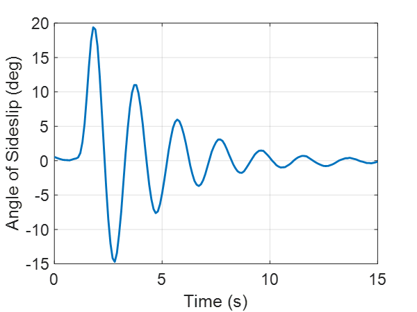
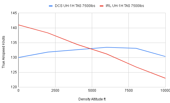
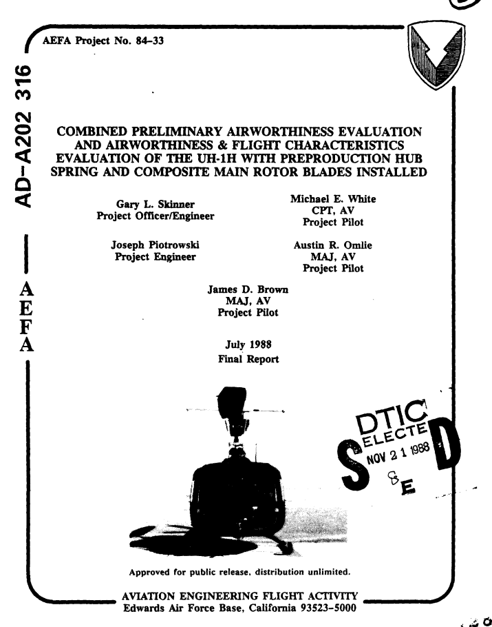
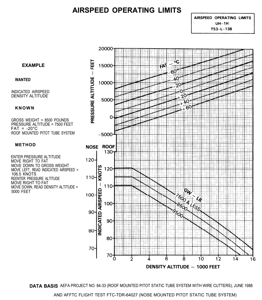
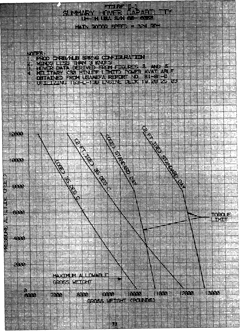
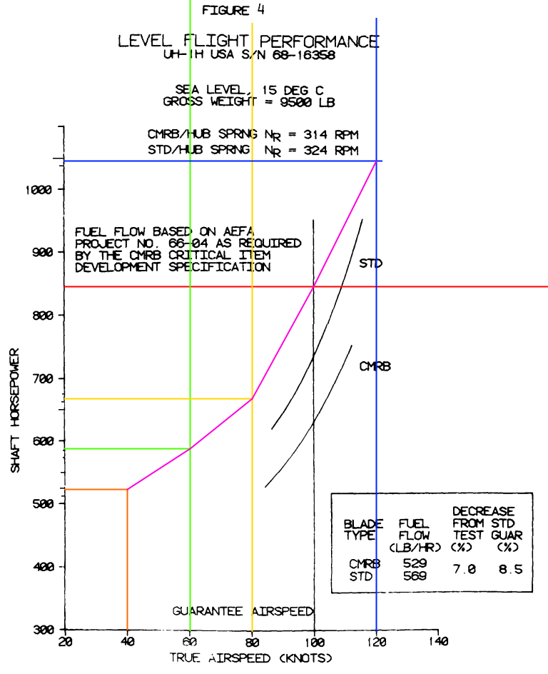
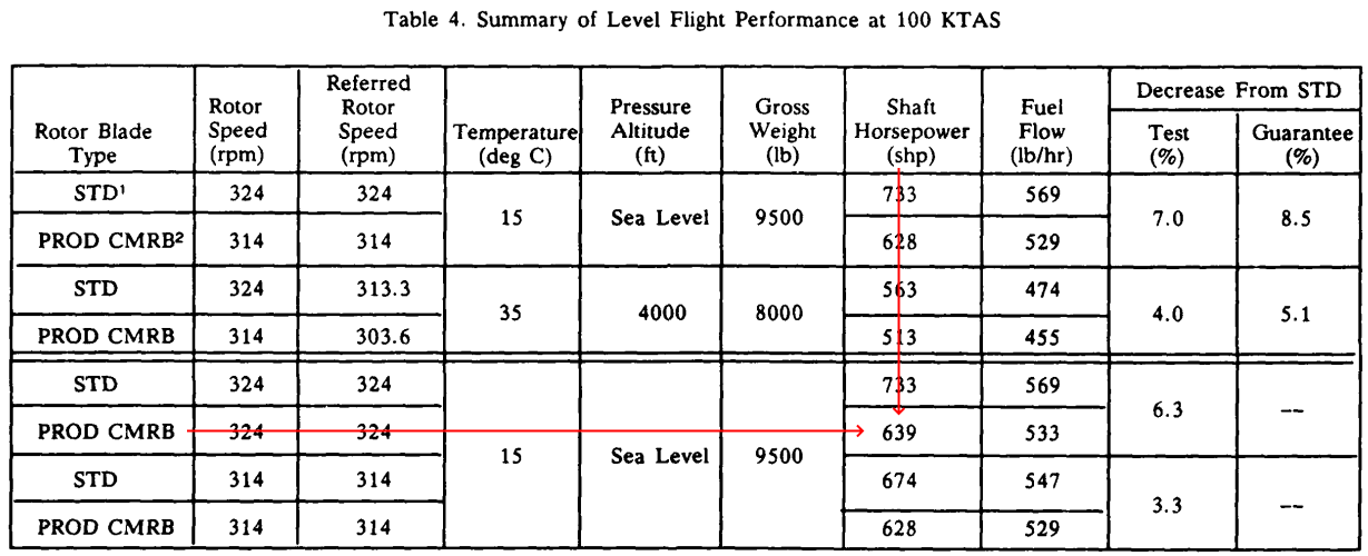
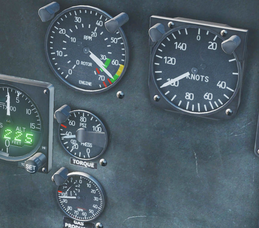
 To put the TLDR first, our huey is underperforming by 3400lbs while being provided a lower available power than the real thing, and made slower than it's actually supposed to be at low altitude (which is where it normally operates) So what are my sources? Before that, lets start with a very simple summary of HOW WRONG the module's performance actually is. null Now, I won't act like that's the whole story with all the context, because it's definitely not. There are things like the transmission limit to take into account. But those sources, lets see them. Here are the 3 main sources, there are several other minor sources as well, however the majority of the data comes from these 3 documents. null So allow me to clarify something, our huey is one with a 1990s refit, it is the one with composite blades. You may have noticed, one of those sources explicitly mentions the composite blades in the title. That source is a performance profiling of our exact model of huey. Refits and all. Now, there's something else to talk about, the huey's operations manual. You might be familiar with this chart. This chart is useless. This chart doesn't tell us where the transmission limit is, it doesn't tell us how much engine power is being used to generate those speeds, it doesn't tell us ANYTHING. That chart is a significant misrepresentation of the huey's performance capabilities, because all that chart shows is a paper limit on the huey's speed. Vne, Velocity, never exceed. A scary term, used to define a speed you are to not exceed for assorted reasons. For the huey, the Vne is in place to keep the pilots from accelerating into retreating blade stall, nothing more. It's a paper limit to keep the pilots safe, it tells us NOTHING about how the aircraft performs. However, if you look at the bottom of that chart, "Data basis AEFA Project No. 84-33" Go back and look at top of the source that mentions the composite blades, that is AEFA Project No. 84-33. The data from that document was used to generate that chart in the manual. So before we go farther, how do we corroborate all our sources to make sure they're on the same page and providing us valid information. Cross checking. Take one set of data, and see if the patterns within it match the patterns in another set of data. We can do that. Here is the overall performance of a huey with the standard blades at 7,500lbs, derived from the data within the UH-1H flight profile performance handbook. Pay attention to the density altitude of 7500ft, you see where the yellow and red (transmission limit and power limit) lines intersect, that is where the engine can no longer provide enough power to max out the transmission. Now here is the hover performance chart from the composite blade document. Look at the rightmost line. "2ft IGE, standard day". You might have already noticed it. Incase you didn't. So our documents are in agreement, what do we do with this information? We start comparing it to the performance of our huey in DCS. Lets start with a more complete performance profiling of the real huey with the standard blades, once again, this data is derived from the UH-1H flight profile performance handbook. This data is for a huey with non composite blades. So there are multiple plots here, let me walk you through them. The first one that likely sticks out is the blue line since it's away from all the others, that is the Vne. The fact that it is placed lower than all the other data reminds us of the chart in the manual. I said that chart was useless, because as you can see by this graph, every single other plot of data performs significantly over what the Vne would have you believe. The next two that likely stick out are the red and teal lines. These are the performance of the DCS huey plotted onto the same graph, the red line abides by the incorrect EGT limit placed upon the module, the teal line ignores said limit and properly maxes out the transmission where it can. Next would be the green and yellow lines, the green line shows the maximum power the engine can normally push, regardless of any other factor, at sea level that would be 1340shp. The yellow line shows the maximum CONTINUOUS power the engine can push. This means the engine can run at this power setting indefinitely without much issue. And finally, the orange line, this line shows the safe limit of the transmission, specifically, 1158shp, or 50psi on the torque indicator. This is the huey's military thrust it can use this power for 30 minutes. This is not the LIMIT of the aircraft's performance, the transmission CAN PUSH HARDER, it just does so at the risk of being damaged. Yes, this means that, per this data, the huey should be able to reach 141knots in level flight. Something you'll notice, the teal line, our huey's performance, can't even reach the transmission limit at sea level. While, conversely, our huey's performance actually PASSES the real huey's maximum possible performance at higher altitudes. So, from this alone, you can see that the module's performance accuracy is not great. But that's not the whole story, that's just for the standard huey, and we haven't even gotten into engine performance per speed yet. We'll do that now. Here is a chart from the composite blade document, it shows the level flight performance in speed compared to the shaft horsepower generated by the engine to achieve said speed at a gross weight of 9500lbs at sea level in 15C temperature air, ISA conditions. On it, you will see a pink data plot. That is our huey measured by the same metric. 9500lbs, Sea level, 15C air temperature, ISA conditions. You'll notice that our huey isn't even performing as well as the huey with the standard blades, let alone the one with the composite blades. But first, how did I get the horsepwer data from the DCS huey, we don't have access to that data. Except we do. We are given the torquemeter, which when combined with the rotor RPM, we can derive the current SHP put out by the engine. As per our previously unreferenced source "Helicopter drive system load analysis". Pages 43-44 detail a formula to do exactly that, derive shaft horsepower from our torquemeter reading, and rotor RPM. Here is that formula. SHP=3.88*((10^-3*Rotor RPM)*((17.76*Torquemeter Torque)+33.33)) Now, you'll notice that graph shows the composite blades as being measured with the rotor at 314rpm, that's ok the difference in the result isn't exceptional, however here is a table showing the same data and including 324rpm on the composite blades. So, 639shp to push the helicopter to 100knots at sea level at 15C at a gross weight of 9500lbs. That would be 26.745psi on the torque indicator in the cockpit. As you can see by the pink line on the graph, however, we didn't even get close. We hit 36, possibly 37psi on the torque indicator at those parameters. Level flight, 9500lbs, sea level, 15C, 100knots. 36psi at 324rotor rpm, as per the formula, is about 845shp, over 200shp too high. Now, we can use this formula to find something dire. Lets make the huey as light as we can and see how it performs. 6100lbs, all it has is about 9 minutes of fuel Sea level 15C 100knots level flight about 30.5psi in those parameters. 722.8shp at 100knots. The real huey pulls 639shp in those parameters at 9500lbs. Our huey, at 6100lbs, is performing WORSE than the real huey at 9500lbs. Our huey is underperforming by over 3400lbs at low altitude. That is unacceptable. Interestingly, these high torque values also explain why we need an unrealistic amount of left pedal, which when combined with the incorrectly modeled tail rotor, brings about some interesting comparisons. So, now that we have the well documented performance profile from the standard blade huey, honestly, we could just use that one for our huey and it would be fine, the overall speed differences shouldn't be drastic, it'd be far more accurate than what we have now. As for why our huey overperforms so much at high altitude, I don't know. All my efforts were aimed at understanding its performance at low altitude as that's generally where players utilize the aircraft. I suspect it may be a combination of the engine not losing enough power at altitude and rotor mach drag not being modeled. However, for now, I believe this should be sufficient to warrant the developers looking at it. Please. Properly implemented, our torque indicator should actually max out at around 58.15psi while the N1% (gas producer) gauge reads 100% As it stands, we are using too much power, to generate too little speed, at too high of an EGT, causing us to have even less power. We are underperforming by over 3400lbs at sea level, it needs to change.
- 46 replies
-
- 38
-
-
-
- uh-1h
- performance
- (and 1 more)
-
I have spent a multitude of hours researching how I can try to edit the avionics and flight model of the CJS Super Hornet. Alas, I have had little to no success. I’m at a loss right now, and I would really appreciate some help. I know little to nothing about coding or computers, so this is all very confusing to me. From all my research, I found that the player flight model for the hornet (also used by the CJS Super Hornet) is a professional flight model. This PFM is a .DLL file and is encrypted. I heard the avionics are also encrypted (probably also in a DLL file [i never found it so I wouldn’t know]). Can someone help? I got DCS for my 15th birthday in July, and I found the Super Hornet a while ago. I just really want to make the flight model more like a Super Hornet. If someone knows how to edit these DLL files(idk if that’s legal. Is it?) please teach me. Or maybe if someone knows how, you could edit it for me I suppose? Maybe a developer could help me, someone with knowledge and authorization? Please, I just really want this. I know the Hornet and Super Hornet are really similar, but I love the little details. I love small changes that make each aircraft different, even if it’s two variants of the same aircraft. I love dogfighting, and I’ve heard of the AoA and slow speed performance of the Super Hornet being even better than the Legacy Hornet. I’d love to experience that. I don’t intend to sell or pirate the DLL files or anything. I know they took years of research and development, and I deeply revere that dedication. I would never steal that work. I’m not trying to pay anyone for this, and I don’t expect someone to help. I’m not entitled to help. However, I just wanted to reach out and see if I can find the right person who wants to help me. All I want is to fly the Super Hornet with my little brother and my friend. Please help, I’m out of ideas. Also, if anyone does help, here are the changes I would love to see: Decreased RCS to around 0.1-0.5 m2 (I think it’s in the .lua but I’ll put it in just to be safe) Increased radar detection range. (The AN/APG-73 did 60nm, but the AN/APG-79 does 80nm; I can detect a plane sooner than Legacy Hornet can) More consistent Radar STT lock (DCS Legacy Hornet loses STT lock a lot; appears to almost be intermittent at times) Increased thrust (to emulate increased subsonic acceleration) Better AoA performance (Legacy Hornet flew at max 35o AoA; Super Hornet allegedly has higher max AoA; 20% better seems like a good estimate) Increased lift (Better slow speed characteristics; more control at low speeds; 20% better seems good) Increased pitch rate (Nose pitches up or down quicker and with more control; maybe 7o faster) Increased survivable G load (requires higher G-force to break wings off airframe) (If I over-explained, I’m sorry. I just don’t know if I used the right aviation terms and want to make sure I’m understood properly)
-
Hi guys, I saw the Casmo's video and one thing seems quite strange to me related to FM. The model in hover mode is very, very stable. I don't know if there is any wind here, but there should be some slight drift. When the missile is fired, it should also tremble and maybe even move back slightly due to the recoil, but nothing, it just stands in the air like a stump. Any comment for this? TY! IRL: With ground effect: For example, the DCS Apache has a slight drift even in auto hover mode.
-
Hello Could someone give me an idea of what the flight models in DCS "look like" and how they are integrated with the DCS engine. What are the inputs and outputs? What data from DCS are accessible for mods and what data is not? Are the FMs a set of equations with different inputs and outputs? Are the FMs a set of tabulated values for each possible flight case? Are they something else? I'd very much appreciate if examples could be provided either as screenshots, formulas or code. All answers are very much appreciated!
- 2 replies
-
- 1
-
-
- flightmodel
- flight model
- (and 4 more)
-
 One of the folks in our squad (Royal Waffles) found this...you can load bombs, then take off WITHOUT adding them to PACS (A2G Armament) and the jet will fly as if it is clean (achieving M1.5+), then while in flight, if you add the bombs to PACS, the jet will suddenly slow down, which suggests that the drag of the bombs is not modeled until they are identified in the armament page. This video shows the F-15E at M1.53, then when the CBUs/etc are entered into the armament page, the speed begins to decrease without any adjustment to the throttle. This can be exploited by flying to the AO "drag free", then entering the armament just before attacking, saving fuel/etc.
- 2 replies
-
- 5
-
-
-
- drag
- flight model
- (and 1 more)
-
 Hi, This thread is about the FCC OFP version 10.7 control logic implemented in DCS, and it's missing important features. Several observations (currently as of 2.9.4) show that a core function, which is described as 'Opposite Differential Stabilators for Roll', is not implemented. This function utilizes adverse yaw to generate yaw rate, enhancing roll coordination and performance at high AOA. A description of opposite diff-stab function, quoted from reference [2]: A description of the sluggish roll performance of v10.5.1, quoted from reference [1]: Video evidence of Opposite Differential Stabilators, from 0:42: This would be very useful in generating proverse yawing moment in the direction of intended yaw, increasing the yaw/sideslip maneuverability of the Hornet at elevated AOA, which is currently lacking in DCS. References: 1. Mitchell, Eric John, "F/A-18A-D Flight Control Computer OFP Versions 10.6.1 and 10.7 Developmental Flight Testing: Out-of-Controlled Flight Test Program Yields Reduced Falling Leaf Departure Susceptibility and Enhanced Aircraft Maneuverability. " Master's Thesis, University of Tennessee, 2004. https://trace.tennessee.edu/utk_gradthes/2372 2. Park, David J., "Development of F/A-18 Spin Departure Demonstration Procedure with Departure Resistant Flight Control Computer Version 10.7. " Master's Thesis, University of Tennessee, 2004. https://trace.tennessee.edu/utk_gradthes/2312 3. NATOPs manual which is not quoted here but contains relevant info.
- 4 replies
-
- 8
-
-
-
- flight model
- flight control
- (and 1 more)
-
I'll share a method to quantify energy bleed rate using the SEP equation Ps = dh/dt + (V/g)(dV/dt) Reference to this equation is at Page 21 of https://dspace.mit.edu/bitstream/handle/1721.1/36378/16-885JFall2003/NR/rdonlyres/Aeronautics-and-Astronautics/16-885JFall2003/1A2F9B8F-B307-4461-83AE-9CCD658DBD50/0/aircraft_murman.pdf Given that a clean aircraft is bleeding its speed at 10000ft from 479 KTAS to 466 KTAS in a 1-sec time span, with a pretty constant bleed rate, and a tiny altitude gain of 1 ft. Then we can dial in all the elements we need: dh = +1 ft dV = -13 KTAS = -21.94 ft/s V = 472.5 KTAS = 797.5 ft/s (took the average) g = 32.174ft/s^2 dt = 1s The resulting Ps = 1 - 21.94 * 797.5 / 32.174 = -543 ft/s at the speed of 472.5 KTAS, or 0.74 Mach. So that you can check with RL figures. F16 speed bleed test 10000ft.trk
-
Given the upcoming DCS F-35A module and after reading through some LM's technical papers about its performance and flight control system designs, I'd like to discuss what I believe might be the most challenging aspects of implementing the F-35's unique flight model and control laws, particularly its NDI (Nonlinear Dynamic Inversion) system. From what I understand, this would be the first implementation of an NDI-based flight control system in DCS. The key challenges I see are: 1. Onboard Model (OBM) and aerodynamic model. The F-35's NDI relies heavily on a detailed onboard model (OBM) of the aircraft's mass properties and stability/control characteristics. How ED is going to handle the complex aerodynamic modeling, especially in the high AOA and transonic regime is crucial, where you have: Nonlinear control effectiveness Strong control surface interactions Complex vortex systems and flow separation effects Transonic roll-off phenomena 2. Real-time Control Solution Computation. Unlike traditional scheduled-gain FBW systems, the NDI system computes control solutions on the fly. Does the DCS engine architecture allow for this kind of real-time computation without impacting performance? 3. Effector Blender Implementation. The effector blender needs to: Compute optimal control surface allocation in real-time Handle control priority shifts (like yaw vs. pitch priority for horizontal tails) Manage control surface interactions at high AOA Deal with control surface saturation and overflow conditions 4. Auto Recovery Systems. The integration of: Automatic Pitch Rocker (APR) for deep stall recovery. (Yes, the F-35 have deep stalls just like the F-16) Anti-spin modes Complex mode transition logic Adaptive filtering systems for yaw rate control It's also interesting to see how ED will handle the transition between different control modes (like the shift from traditional roll command to yaw rate command at high AOA) while maintaining the "feel" of the real aircraft. This would be a unique kind of FM and FCS to witness in DCS. Cheers and take a read at https://arc.aiaa.org/doi/10.2514/5.9781624105678.0525.0574 (F-35 High Angle of Attack Flight Control Development and Flight Test Results)
-
i noticed something very strange on all Flankers the can´t even pull 9 G turns at max something like 7.6- 7.9 G and and it doesn't matter without or with full weapons on the pylons. i only can achieve the 9 G with the ACS or Override control stick limitation button and that brakes the wings instand that seems odd to me that the flanker can´t pull 9G in a high speed turn and the F-15 for example can well exceed the 9Gs without a problem Flanker not even 9 G turn.trk F15 easy 9.5 G till blackout.trk Flanker high G turn.acmi
-
Heya all, I got hooked with the Mirage F1 lately, and I tried to do some stuff here and there. I understand that this is still early access and I found this module to be actually very nice and engaging (Both models) But - Is this flight model some kind of accurate right now? or is it planned to change significantly in the future. I am feeling it veeery heavy(Even naked with half fuel) - and i don't thing it can dogfight at it should be , it is very dead at low speed, and it should not be that much. What you think?


.thumb.jpg.33aab815740c9891f93c0e0ee2c18a5c.jpg)