Search the Community
Showing results for tags 'mfd'.
-
Hi everyone, Contrary to this thread being marked as fixed and locked, there are still problems with the cursor in the F-16. I'll copy and paste what I had written there as all of it still applies: Certain pages in the F-16 have the cursor move at inconsistent speed when changing direction, leading to it appearing to jump. It's most commonly seen when going left/right and then adding some up/down. As far as I can tell the following are affected: The HUD (for instance, CCRP, DTOS, Maverick VIS etc). The HAD page (though the cursor does move more smoothly - as if its position is updated at a higher rate compared to every other page. Unsure what the rate should be). The WPN page for HARM. Everything else appears to work as it should and motion is predictable (though the rate at which the position is updated seems to be lower than the HAD page). No other module appears to suffer from the same bug (the A-10C for instance is very smooth and very consistent, with the exact same control on my stick bound), there are also no conflicts in the control set up. The track I originally posted can be found in the previous thread, as can my control profiles for both the A-10C (which shows no issues) and the F-16CM. Here's a video to show what I am seeing (this is after a recent calibration), this video is before recent updates but still depicts exactly what I am seeing with the most recent update at time of writing (2.9.20.15010). Note the following: The FCR and HSD pages don't show this issue - the cursor behaves entirely predictably and there are no sudden rapid accelerations - all good. However, the HAD, HARM WPN page and the HUD (here shown in DTOS, but the same applies to say, Maverick in VIS mode or any other mode using the HUD's cursor), show sudden, rapid accelerations when the switch is moved in a circular fashion. When I make just max X or just max Y inputs, the cursor generally moves more slowly and sudden, rapid accelerations are less frequent (though not entirely 0, you can sometimes still see the cursor suddenly start moving very quickly). The bug appears to affect the Y-axis more than it does X. The sudden, rapid acceleration of the cursor occurs when changing direction. Towards the end of the video I show my control bindings, you can see that my control moves as smoothly as I can make it. It properly re-centres to 0 and I can move it to the extremes of either end without any observable jitter. Here's a video showing what happens when I try another module, here I try the A-10s TAD cursor and the HUD cursor - note how there is no sudden rapid accelerations and the cursor behaves completely predictably and is generally very smooth. I also again show my control bindings and test, you can see that the exact same control is bound and (aside from not being inverted) the same exact settings are used: Every other module I've tested (A-10C II, AV-8B, F-4E, F-14A/B, F-15C, F/A-18C, Ka-50, Mirage 2000C, Su-25, -25T, -27S, -33) work as they do as seen in the A-10C video - smooth, predictable motions, with no sudden rapid movement - if I move the control to its extremes the speed of the cursor stays clamped. It is only the F-16CM and only for the HUD, HAD page and HARM WPN page that exhibit this issue, other pages (such as the FCR, the HSD, the Maverick WPN page, the TGP page etc) show no issues.
-
Hey guys, I was watching a video online and it mentioned that the symbology and letters on the MFDs in the F-16 in real life are bolded with black outline, so that against white background (e.g. when using the Tpod) the crosshair and the symbology can be still highly visible. I think there is also an option to set the writing on the MFD to yellow, so that it is clearer against white background? Is it possible that you could please implement an option that lets players set their f-16 MFD text colour to yellow, just like you did with the canopy tint colour option? Many thanks. (Pictures attached are from Caracal 1-4|Cipher's Yellow MFD Mod, as a reference) Kind regards Prove_It

-
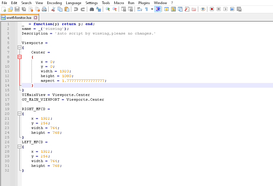
 Razbam's AV-8B Harrier Module allows you to toggle MFD Exports within the bindings. This essentially allows for "Dynamic" Exporting of MFDs for products such as the WinWing MFD, allowing you to use 1 MFD as multiple. I request that all aircraft have this feature as it allows proper use of the MFD Exports, especially given that Dynamically Exporting is not possible in the current version of DCS. Example Video (AV-8B Harrier Module): 3 in 1 Mode Working Example.mp4 Lua Edit: For those wanting to recreate this for their own WinWing MFDs, just edit the wwtMonitor.Lua to have both Monitors show. Then use 3 in 1 mode in WinWing App. Bind the Toggle to whichever button you want.
- 2 replies
-
- 1
-

-
- mfd export
- mfd
- (and 3 more)
-
I recently moved, so I had to completely tear down my setup and move it. After setup, I can't get my Winwing MFDs to work. I have the full "top gun MIP" setup, with the UFC, HUD unit, and 3x MFDs w/ displays. The displays are working properly. The MFD portion with the buttons is not responding at all, on any of the 3 MFDs. When I plug them in I don't get a ding from Windows saying a USB device has been plugged in. I've tried moving the cables around. I plugged the USB-C cable from the working UFC unit into the MFD and nothing. I have everything plugged into a powered USB hub. I tried plugging the MFD directly into my computer, still nothing. They don't show up in SimAppPro or in DCS. I tried restarting with them plugged directly into my computer. Still nothing. Any suggestions?
-
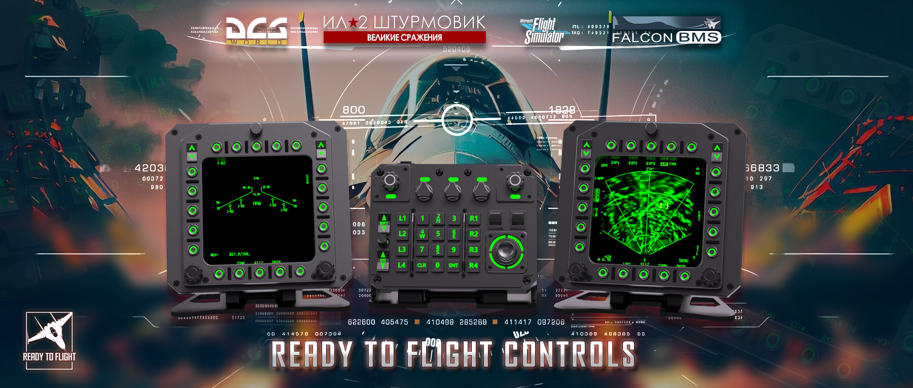
Всем привет, на связи RTFC. Мы разработчики игровых устройств для авиасимуляторов. В этой теме мы будем выкладывать новости о наших устройствах и показывать как происходит их разработка и изготовление. Всем привет! Показываем вам наши рабочие будни, сегодня мы печатаем рамку для обновленного MFD - Bullseye из ABS-CF. ABS-CF - это пластик наполненный мелким углеволокном, благодаря чему детали из этого материала обладают повышенной прочностью и имеют красивую текстуру из за высокой спекаемости слоев. Как вам качество? А больше информации вы найдете у нас в группе 3d print_frame.mp4
-
Total Controls is right now cooking up something new. An Apache MFD frame sized as the real deal. The buttons will be backlit with adjustable lighting. The VID-knob will have a center detent just like in the real helicopter. There will be an option to use it to the left or to the right to avoid input conflicts in Windows. The image shows a mock up, but it is very close tho the final product, however it will be more polished. We can not say an exact price rigth now, but we aim at around 100-120 USD per unit and release it planed to sometime this spring. We will sell discount bundles and separate table mounts.
- 230 replies
-
- 24
-
-

-

reported earlier Sighting point label on FCR and TGP formats
Frederf posted a topic in Bugs and Problems
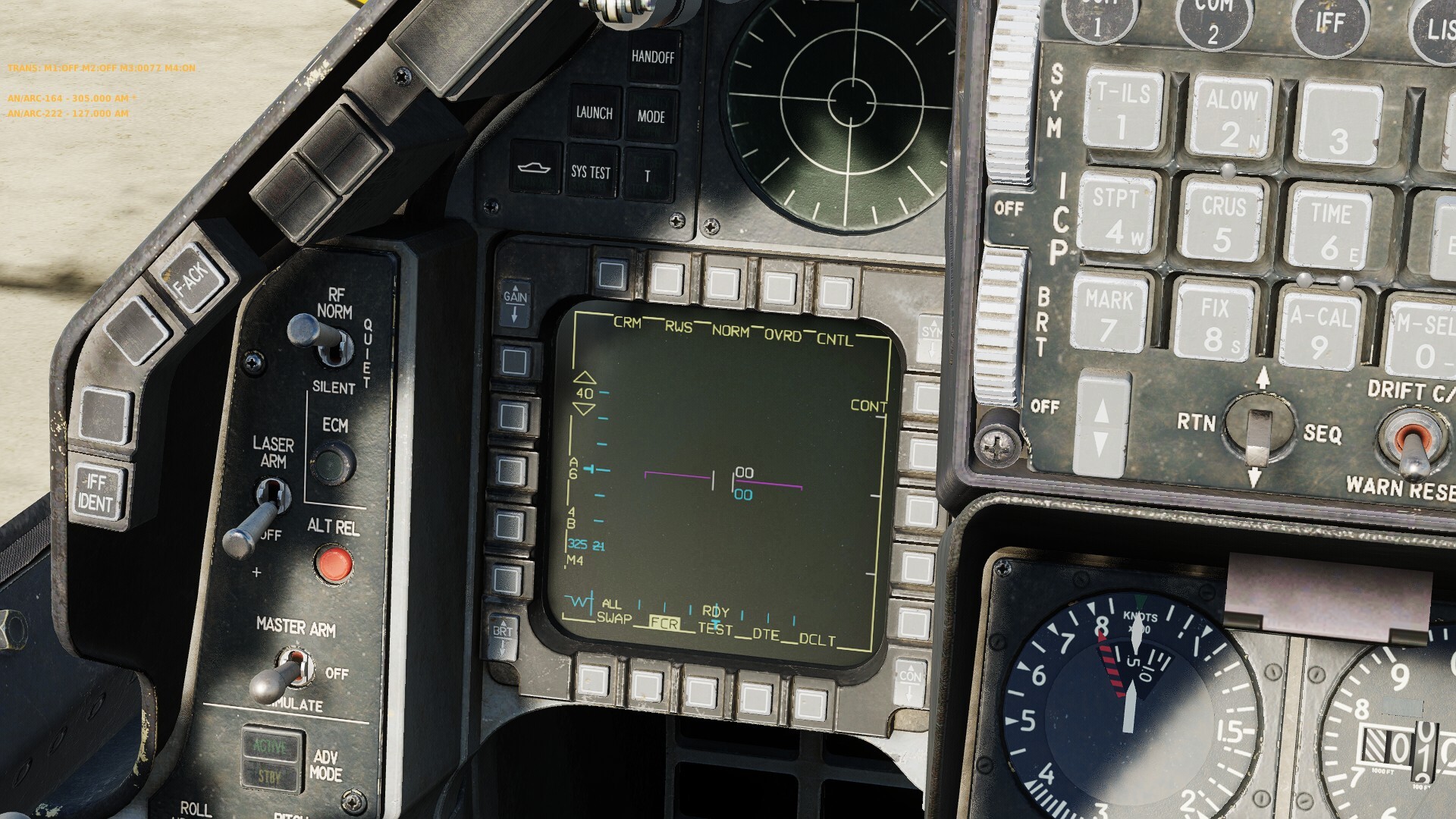
Label next to OSB10 on the FCR format shows "STP" instead of the correct "TGT" on FCR format when no TGP is carried. "TGT" label should be used in all preplanned AG modes instead of "STP" and labels for FCR and TGP format should always match. Aircraft without TGP Situation in which STP should be displayed: NAV, ACAL, FIX, AG MAN, SJ/EJ* Situation in which STP should not be displayed: AG VIP/VRP, NAV VIP/VRP**, CCRP, LADD, EO PRE, EO BORE, DTOS, CCIP, STRF^ Aircraft with TGP Situation in which STP should be displayed: NAV, ACAL, FIX, AG MAN, SJ/EJ* Situation in which STP should not be displayed: AG VIP/VRP, NAV VIP/VRP**, CCRP, LADD, EO PRE, EO BORE, DTOS, CCIP, STRF^ Correct Cannot Observe Not Correct Unknown *Unable to change FCR to GM type mode in JETT **Unable to select VIP/VRP in NAV master mode ^Documentation says that sighting rotary should be blank in AG visual modes which is the case in AGR but unsure if it should also be blank if the pilot changes the FCR to GM type as well. In DCS in AG visual attack modes and FCR shows a label it is "STP" or "TGT" depending on if TGP is loaded and not blank. F16 Sighting Point Label STP without TGP.trk -
I've been trying to learn how to export cockpit displays for a while. I've searched both ED forums and basic Google searches. There is so much content on the subject now, and a lot of it contradicts the other. Could someone please, either point me to a column or post that explains the basics for exporting MFDs, etc. to my second monitor? Or, post a tut or demo .lua on which file and what lines need to be modified to do a basic second monitor export? I'm wanting to export to my second monitor for now. But, I'm scratch building a universal panel and would like to learn this, so I can export to the small monitors I'll be using when it's finished. Here is my display setup now, it's a really basic stacked. Thanks for any help
-
Just peeled my first rough draft/prototype part off of the printer bed. I'm building a rudimentary, universal front panel for DCS. I'm finishing up on designing the MFD housing. The recessed, through hole perf board will hold my tac buttons and hopefully have my small displays centered on them. I'm just getting started on the UFC, not sure what all I want to include on the up front control. Want to keep it fairly simple, fairly portable. And, universal for all the modern aircraft in DCS, especially the Apache Mod. Not a big deal, but I'm pretty excited for my first 3D design and print....and it's for DCS!
-
 Is it possible for me to connect a smartphone and/or tablet device to the game and configure it so that the MFD displays of various jets (Shvkal display on Su-25T, Radar on F-15C etc) are shown on the connected device?
 -
Hi. This issue exists for a long time really. When I press HUD button on MFD-Cougar, my 8" TFT screen displays really heavy blurred HUD. It has been there for months, maybe more... I may be wrong but I remember that I've opened a thread or written on a thread about this, but couldn't find. So, opened again. Is there any move on this issue? Thank you.
-
Check out the link-http://ebay.us/sLfZdx?cmpnId=5338273189 LILLIPUT UM-80/C/T 8” USB Touch Screen Monitor | Plug&Play | USB Only | 2 Screens Included 2 LILLIPUT 8” touch screen monitors with USB cables. Great condition due to not using them very much in the past year. Simply plug the usb into any computer or laptop and you have an additional touchscreen monitor! One cable was missing when I bought this so i replaced it with a working cable last year, everything is still in perfect working order. Still have box and instructions!
-
 Got a new SSD. I "cut" then "pasted" DCS from my HDD to my new SSD. I sometimes run IHOPIworks Device Server. Screen Exporter Every MFCD in the game is now blank. A10cii, Ka50, Harrier (with export app not running or not) Im Constantly losing my Game Settings. (Once a day i have to change Audio levels/Music off, change cockpits to english, turn on rudder trim in Special, driving me nuts) The Export App, starts then disappears. I cant run it, even if i wanted to. I deleted, SCRIPTS folder in the Users/SavedGames I ran repair a couple days ago, no change. This morning, DCS is crashing just trying to boot fast-game to take screenshots I pay for data.. so id rather not re-download 200 gigs. I spend more time trying to fix DCS than playing it.
-
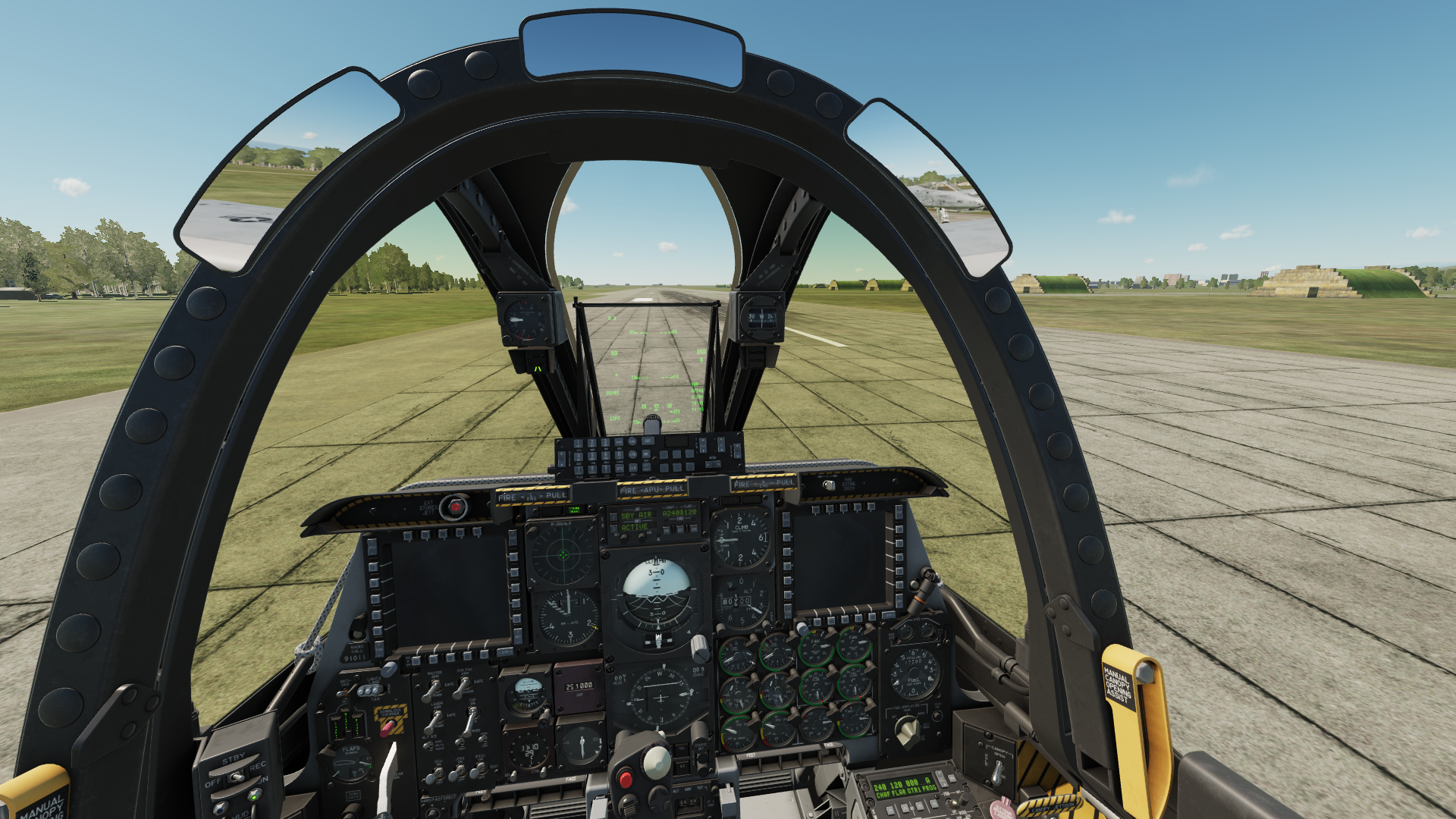
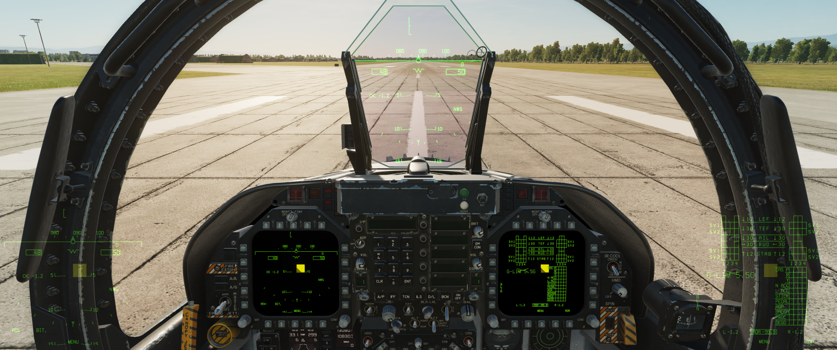
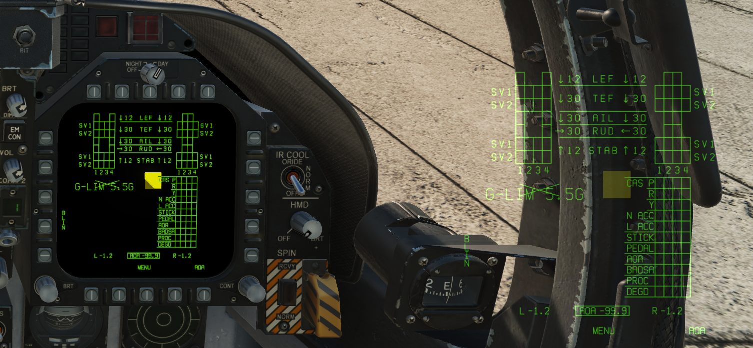
When attempting to boresight thermal MAVs in the F16 at night (day too I believe) it is impossible to see the OSB button prompts on the screen due to a bright white background (usually sky or even buildings) because the OSB text is also white. I am at work at the moment and I don't have any screenshots but I imagine someone has run into this issue or could reproduce (I will edit in screenshots when possible). I tried adjusting all the brightness/gain/contrast controls around the MFD but it did not help make the OSB text visible. I am curious if anyone has any tips or even a mod to add an outline around the OSB text to help distinguish it from bright backgrounds. Thanks
-
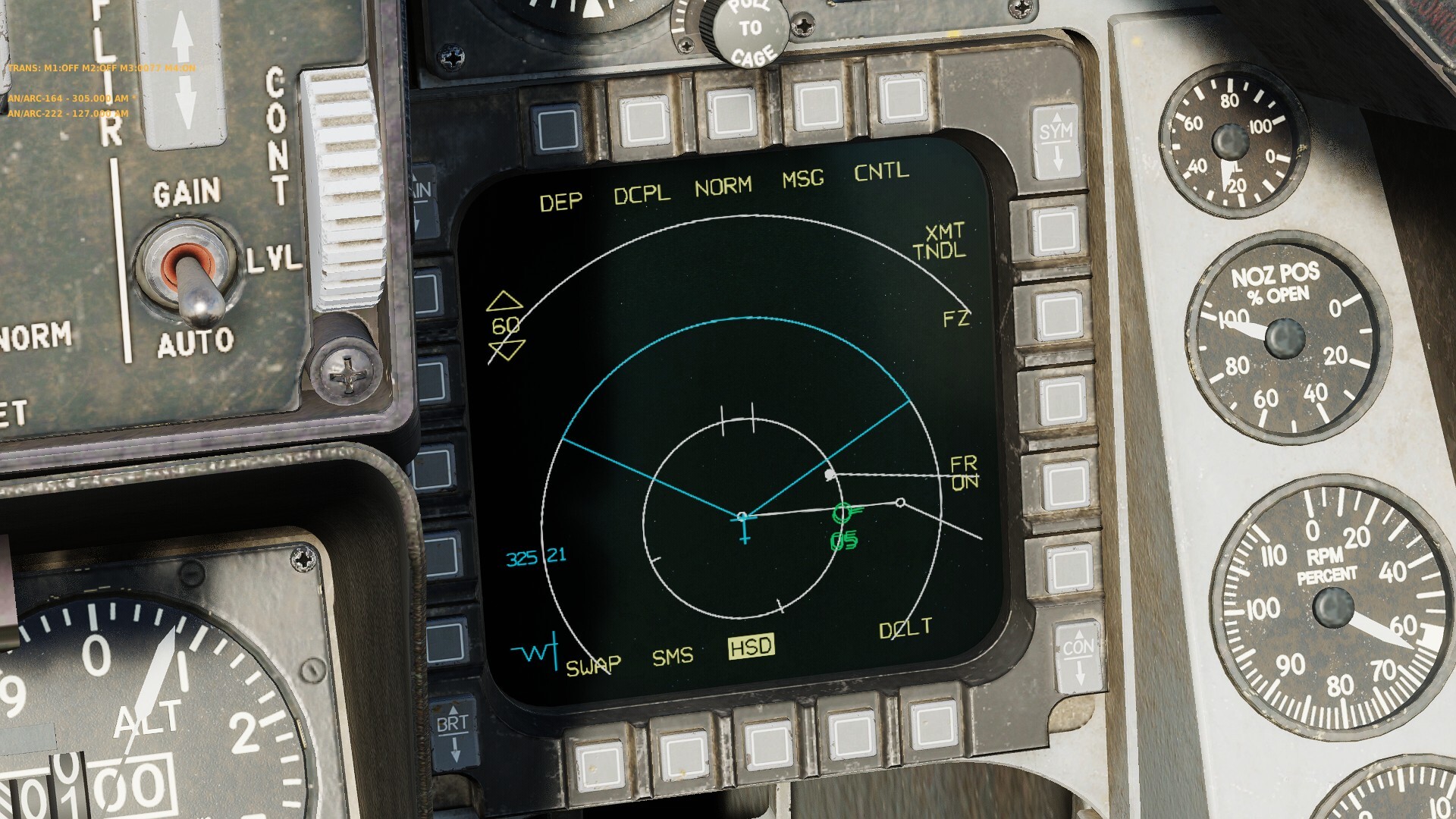
OSB 6 contains in the rotary BARO (default), RALT, PR for barometric, radar altimeter, passive ranging (DTS) respective selection for secondary AG ranging sensor. OSB 9 has CZ for cursor zero function. Lower left corner has "W" navigation symbol or bullseye bearing-range symbol depending on UFC option selection. Colors are not representative of actual. Text OSB labels are white and navigation symbol is cyan.
-
Just installed a pair of lcd screens behind the Cougars. It looked okay, but the frame drop and stutter is unforgiving. I have a Ryzen 5600x, 6800xt, 32gb, 165hz monitor @ 3440x1440 rig which is quite smooth with all graphic options pushed to max except for AA and RT . (only play SP so far) But once I start pushing screens to the MFDs, it is choppy as @!₩#. (freesync is off) I am exporting via monitorsetup lua file adjustment(file attached). Freesync is off and total resolution on options is 4240x1440p (MFD LCDs are 800x600 each and are stacked on top of each other/ to the right of center screen) ANY Help would be greatly appreciated MFD export.lua
-
After I drop the tanks, the right MFD screen swaps to show that, but I can't figure out how to set it how it was before I drop the tanks. After the drop, I can no longer switch between A/A A/G or Nav anymore. I must be doing something dumb or there's a helpful action I don't have mapped.
-
 As someone who flies aircraft with mirrors and multi-function displays such as the F/A-18, AV-8B, and soon the F-15E, I would like to suggest something. In the settings, you have "Res. of Cockpit Displays", which controls the resolution of the MFDs' image quality and cockpit mirrors. Personally, even though it decreases performance, I like to use my mirrors, but if I want to reduce the MFD resolution to have a more realistic LITENING image, my mirrors will also have their resolution halved. Since it's something simple and the F-15E is very close, I think it'd be a good idea to make a setting "Res. of Cockpit Mirrors" and change "Res. of Cockpit Displays" to only affect the MFDs.
 -
I did a lot of research on this one and found several people with a similar issue, but no correct answers, so I figured I would post my solution. Issue: I received my new Cubesim MFD and hooked them up. When I added the Cubesim lua it did not work. This lead me to download and configure my viewports with Helios 1.6. This work great to get the viewports using the generic MFD left and MFD right onto the Cubesims, but when I jumped into my trusty F-16C the backgrounds on the MFD were transparent and showing the clouds and ground as I flew (see photo of Cubesims). After hours of troubleshoot and endless Google search's I realized what has happening on my setup. I had my monitor setup to the top right of the main screen (see attached red frame drawing). What the view port was doing was displaying an extension of the main screen view similar to using multiple monitor setups where you want to see more of the world to the left and right of the main monitor. Solution: Simply relocated the Cubesim monitor to the bottom of my main screen and redoing my monitorsetup with Helios. Now everything functions fine. I also switched to the Helios F-16 patched viewports. This affected the location of the viewport from the original location with the generic MFD viewport. I seen in other post that people were have an issue with the alignment of the view port in Cubesim MFDs so I will share my setup using Helios 1.6 to help. Main monitor 3440x1440 Left MFD 800x600 Right MFD 800x 600 Helios setting for both MFD 600x600 left 90 top 0
-
Hello F/A-18 pilots and LUA programmers, Using the provided display preset to export the left and right DDI's on the same monitor. I can use those because of my ultrawide. The DDI's are not readable without a background. i managed to add a mesh to the DDI's but i cant get them to be fully opaque. This is the code used in MPD_BASE.lua. the colour of the material is for debug purposes. The goal is to get the yellow square to be fully opaque so i can make it black and use it as the background. Thanks for the help in advanced, NCC1701JR MPD_base.lua
-
Hmm how to fix this in the Home Cockpit, the Thrustmasters MFDs have way to little buttons to could accommodate this. The Apache MFD has 31 buttons and 3 knobs, see the picture. I am considering changing the Thrustmaster MFD with two Elgato Steamdeck XL, they got 32 buttons. Any of you guyz have come up with a solution to this.
-
Hello, I have already purchased the 2 pack for my setup but need one more and I cannot find a single one for sale. Does anyone have an extra to sell? OR Is anyone interested in buying one if I get another 2 pack? Thanks,
-
With the new patch update in open beta, the harrier MFD labels are beyond blurry. It’s like they are too bold of a font. I have used the gain and other buttons but still blurry. I never had this issue prior to the update and if I didn't know which buttons to hit, I wouldn't know where to click. Anyone else having this issue or how to fix it? I dont have this problem in the F18 or A10
-
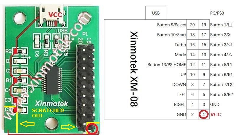
This is my idea, but not finished yet. Basic parts: 2x Thrustmaster MFD Cougar 2x ZGYNK 8' 2x DP to HDMI conversion cable 1,5m 1x USB hub D-LINK H7 1x Lenovo TAB 3 8' + DCS UFC apk 1x Xinmotek XM-08 (button bar) 10x Button TS-12 (green light) Button bar 3D print https://www.thingiverse.com/thing:4755643 1x Lenovo TAB 3 8' + DCS UFC apk 4x USB extension cable 30cm (wireless headset, wireless mouse, PS2cam for TrackIR, free) 1x USB to Micro USB extension cable 20cm (Xinmotek XM-08) DDI panel - Plán.pdf DDI panel - Díly 7_2MM - TAB 8.pdf FA-18 BTN BAR PCB.pdf
- 2 replies
-
- 1
-
-
- thrustmaster
- mfd
- (and 7 more)
-
 So this was driving me insane... one of my MFD 's would consistently disappear... but, I couldn't find the conditions under which it would disappear, I thought I had a cabling problem ... nope... I thought it was that the script I was using to create 128 buttons in TARGET... nope etc... A little about my controller set up: Thrustmaster Warthog HOTAS which I configure using TARGET, to get a full 128 buttons MFG Crosswinds v2 3 x Thrustmaster Cougar MFD 1 x Razer Tartus (configured as a joystick button box, because I prefer discrete DX button presses, as it creates less confusion keyboard collisions etc) 1 x Stream deck (configured as a joystick button box, using vjoy, because I prefer discrete DX button presses, as it creates less confusion keyboard collisions etc) I obviously turned of vjoy first and thought that fixed it but then in game, nope it would not work, re scanned device etc... nope still nothing ... I start looking into the Game Controller UI in desperation. Clue 1 I noticed that my MFD2 wouldn't configure correctly via the Game controller UI (even though it would still work in game) it would just show as a joystick, but, labelled as the Tartus so I pulled each of the controllers in turn, until i got it up as MFD... turned out it was the Tartus Resolution 1 I changed the MFD from MFD 2 to MFD 4 (luck more than logic) in the Game Controller UI, with the Tartus unplugged, each MFD number has a different VID in windows, so i guessed it was colliding. Each MFD now showed up correctly as an MFD the the Game controller UI. I ran Target and low there were still three MFD's hurrah ... or so i thought... I get into game and the MFD3 has gone AGAIN... some muttering (well swearing) what the hell is going on. Clue 2 why the hell do i have VIVE controller listed in DCS. 2nd order diagnostics (when does the MFD vanish) ... after many stages of testing it MFD3 only vanishes once Steam VR starts only when i have one or more hand controllers active (assumption what if to do the game controller mapping in SteamVR they are mapping the controllers to a VID that just happens to have collided with the MFD, as the newer device they would overwrite the existing device and the MFD vanishes, only if you run TARGET Resolution 2 Change MFD 3 to MFD 8 to see if that works it does hurrah Are we nearly there yet... no we bloody aren't Turn back on vjoy that works, turn back on the tartus and OFFS the configuration of the MFD4 via the Game Controller UI has c*cked up again... note the device works in game but FFS I won't less this beat me... Resolution 3 Turn the Tartus off Move the MFD to 7 because that is next to 8 that will be safe right ... wrong ... well 5 is next to 4 ... wrong ... 6 hurrah! Finally Left MFD1 is fine, my Right MFD is set to MFD6 in the UI, and the Center to MFD 8... conclusion getting multiple MFD's to work with multiple joystick devices is a complete pain in the bottom, and it would be really nice if the manufacturers would use a mechanism of ensuring their virtual joysticks dont collide with each other...


.jpg.6f7e68f40eeb623461f2b0d8f160699b.jpg)


.thumb.png.00ea7794b65f99e95b936215af6daea0.png)


.jpg.67bd9b4c55de987efdf0817ec645db2e.jpg)
.jpg.2b8db791dfd456fe14b7cb358c674771.jpg)
.jpg.882cf00aca17107ed33938988310f236.jpg)
.jpg.c465f8e3129940a0fc270d6668e4eee9.jpg)
.jpg.3a0da865cec47932c37b668079233e3a.jpg)
.jpg.35ecce581bef76e9f2c18157db2d755f.jpg)
.jpg.3445ce3033d33142b12a941449103318.jpg)
.jpg.23910353a376f76bb7d5586f265d728b.jpg)
.jpg.9ee9ba220b89ab15d70f9487cfa0b5b8.jpg)
.jpg.5d15eed9305ea776efa7e71c6933e5a0.jpg)
.jpg.72d85fd22339441bec04f8f820071166.jpg)